
MANIPULATOR-DEPLOYED SYSTEMS FOR SURFACE
DECONTAMINATION IN NUCLEAR FACILITIES
Jan Bremmer, Sascha Gentes and Nadine Gabor
Karlsruhe Institute of Technology (KIT), Institute for Technology and Management in Construction (TMB)
Technology and Management for the Decommissioning of Nuclear Facilities
Am Fasanengarten, Geb. 50.31, 76131 Karlsruhe, Germany
Keywords: AMANDA, MANOLA, Manipulator, Vacuum Technology, CompactRIO.
Abstract: Due to the phasing out of nuclear energy in Germany there are a growing number of nuclear facilities that
have to be decommissioned within the next years. In this context a multitude of surfaces in nuclear facilities
have to be decontaminated. Manipulator-deployed systems offer a suitable solution and are properly
designed for this kind of task. Beyond that they can be used for the processing of surfaces in civil as well as
industrial fields of application, e.g. the stripping of coatings on metal surfaces. By the use of a suitable
supporting system various attachments like a milling machine or laser can be carried and operated on walls
and ceilings. Vacuum suction plates guarantee the interconnection between the supporting system and the
object to be treated. Due to the intricate processes as well as the required flexibility arising from the multi
purpose use with milling or laser attachments a robust control system with a high performance and a high
level of customization is required. The following article introduces to you the systems in detail.
1 INTRODUCTION
Due to the phasing out of nuclear energy in
Germany there are a growing number of nuclear
facilities that have to be decommissioned within the
next years. In order to successfully dismantle and
decommission these facilities a great amount and
variety of processes and actions is required.
Among other things these include the qualified
decontamination of surfaces. The associated tasks
are manifold, ranging from simple cleaning to
complete surface ablation. The latter is particularly
challenging due to the multitude of surfaces in
nuclear facilities that have to be decontaminated.
In this regard, effectiveness and economic
efficiency play an important role as well as the
avoidance of secondary waste and cross
contamination (Gentes, 2006: 416, 417). Therefore
the selection of an appropriate process and system is
crucial.
But only a few of the currently available
processes for the decontamination of surfaces fully
meet the required criteria and are applicable for this
kind of task. Therefore the nuclear industry calls for
more suitable and efficient decommissioning
technologies.
The Institute of Technology and Management for
the Decommissioning of Nuclear Facilities at the
Karlsruhe Institute of Technology (KIT) has
addressed itself to this task and thus is conducting
research as well as is developing innovative
processes and machines for this kind of purpose. All
this is done in co-operation with industry partners
that are focused on carrying out decommissioning
activities in the field. This kind of co-operation helps
to generate feedback in order to improve the
machines.
2 THE BASIC IDEA
The decontamination of surfaces in nuclear facilities
is an intricate and time consuming process. It is very
labour intensive, because most techniques are hand-
operated or difficult to handle by just one person.
Compared to the output of a machine the
performance of labour is very low. Thus more labour
is required in order to be cost-effective.
Furthermore the timeframe for works conducted
in the hot zone, which is the controlled area inside of
a nuclear facility, is very limited per worker and
377
Bremmer J., Gentes S. and Gabor N. (2010).
MANIPULATOR-DEPLOYED SYSTEMS FOR SURFACE DECONTAMINATION IN NUCLEAR FACILITIES.
In Proceedings of the 7th International Conference on Informatics in Control, Automation and Robotics, pages 377-381
DOI: 10.5220/0002941403770381
Copyright
c
SciTePress
shift (HVBG, 2004: app. 2), due to the required use
of breathing apparatuses. Because of that several
teams have to be employed on alternating shifts to
ensure a proper exchange of labour which finally
results in a better practical performance.
Another important aspect is the high effort that
comes along with many of the techniques being used
for the decontamination of surfaces. In numerous
cases scaffolding is needed, especially in rooms with
big ceiling heights. Besides that extra time is
required for the set-up of equipment or machinery.
But the time spent on works preparation reduces the
overall period available for decontamination. Thus it
makes even suitable techniques less effective.
Based on these facts the idea was born to
construct and build a manipulator that is able to
climb on walls and ceilings autonomously, in order
to decontaminate surfaces by means of a milling
attachment or laser. The manipulator requires no
scaffolding or elaborate set-up. Besides that there is
only one operator needed to run the machine. Finally
the use of a manipulator results in a greater
economic efficiency.
3 MACHINE SPECIFICATIONS
Several requirements have to be met for the
successful decontamination of surfaces in nuclear
facilities. Besides the requirements requested by the
clients, e.g. regarding safety and economic
efficiency of the particular technique, there are
requirements that originate from the structural
conditions of a nuclear facility.
The relevant criteria have to be taken into
account when setting up a manipulator system.
Hence the following specifications have to be
implemented:
The manipulator is required to have a low self-
weight. This enables the operator to move the
system through the facility. In some cases the
support of a trolley might be useful.
Furthermore a modular layout allows the
operator to move the manipulator through small and
narrow openings by disassembling it partly.
In this case a low single-weight of each module
is essential to allow lifting them by one person only.
Moreover the disassembly as well as assembly of
the manipulator should be feasible in a very short
period of time. Therefore the use of quick fasteners
is recommended. The entire system has to be
flexible and rugged.
In order to meet the performance requirements
an output of at least 10 m
2
per hour is essential and
the minimum requirement of the clients.
Beyond that an autonomous operation of the
manipulator is advisable to keep the labour costs on
a low level.
Not less important are safety features that assure
a safe operation of the entire system. Here an
emergency shut-off is the minimum requirement.
But due to the fact that the manipulator can be
operated on walls and ceilings by means of vacuum
technology it is also a prerequisite to prevent the
system from falling off the object that is being
treated.
In this regard pressure monitoring and the use of
check valves is important.
Furthermore the control system needs a proper
set up that includes safety procedures.
4 MACHINE BUILD-UP
4.1 Basic System AMANDA I
According to the basic idea, a first manipulator
system was built in the course of the research project
AMANDA.
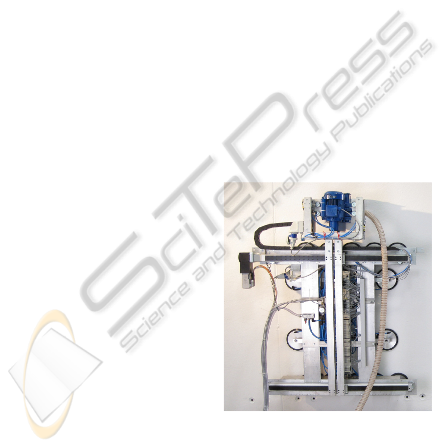
Figure 1: AMANDA I in wall operation.
AMANDA stands for Autonomous Manipulator
for Decontamination Assignments. The system can
be operated on walls and ceilings by using vacuum
technology. It is equipped with a milling attachment
for decontamination purposes.
ICINCO 2010 - 7th International Conference on Informatics in Control, Automation and Robotics
378
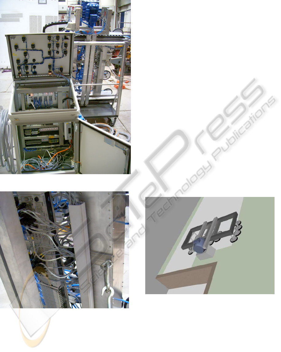
Figure 2: AMANDA I with control unit.
Figure 3: CPX Valve Terminal of AMANDA I.
The control unit which is shown in figure 2 is
based on a FESTO SPS. It is mounted in a switch
box underneath the control panel. The SPS is linked
with the CPX valve terminal on the manipulator via
cable. All pneumatic valves as well as all sensors for
the positioning of the pistons and for pressure
monitoring are connected to the CPX valve terminal.
The valve terminal is shown in figure 3.
In contrast to the valves and sensors, the servo
drive which moves the linear drive unit is directly
linked with the SPS by cable.
4.2 Successor System MANOLA
Based on the principle of the stand-alone
manipulator for decontamination assignments
AMANDA I the successor system MANOLA is
currently under construction at the KIT. MANOLA
is funded by the German Ministry for Education and
Research under the reference key 02S8548.
MANOLA stands for Manipulator Operated
Laser Ablation. The support system is operated with
vacuum technology as well. Instead of a milling
attachment MANOLA carries a laser system that is
used for the ablation of both, contaminated and
uncontaminated concrete surfaces and coatings.
MANOLA is built according to the specifications
listed in section 3.
To allow the transportation of MANOLA inside
of a nuclear facility the system is equipped with a
trolley. The trolley consists of an undercarriage
fitted with rubber tracks, and a loading platform.
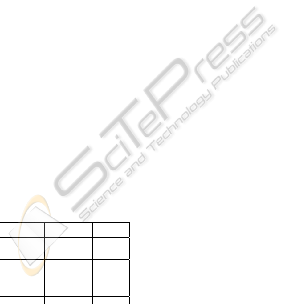
Figure 2 shows a visualization of MANOLA in wall
operation. Beyond that, MANOLA can be operated
on ceilings as well.
Figure 4: MANOLA in wall operation.
5 MANOLA CONTROL UNIT
5.1 Processor And Chassis
The control unit of MANOLA is based on the
CompactRIO System that is distributed by National
Instruments. ‘National Instruments CompactRIO is a
small rugged industrial control and acquisition
system powered by reconfigurable I/O (RIO) FPGA
MANIPULATOR-DEPLOYED SYSTEMS FOR SURFACE DECONTAMINATION IN NUCLEAR FACILITIES
379

technology for ultrahigh performance and
customization. NI CompactRIO incorporates a real-
time processor and reconfigurable FPGA for reliable
stand-alone embedded or distributed applications,
and hot-swappable industrial I/O modules with built-
in signal conditioning for direct connection to
sensors and actuators’ (National Instruments, 2009).
The setup of the system applicable for
MANOLA consists of an embedded real-time
processor with 800 MHz, 512 MB DDR2 RAM, and
4 GB storage. The processor is connected to a 4-slot
Virtex-5 LX50 reconfigurable chassis that will be
installed on the MANOLA trolley. Furthermore two
8-slot deterministic chassis will be installed on the
manipulator itself for embedding all sensors and
actuators of MANOLA. Both chassis on the
manipulator will be linked with the main chassis on
the trolley in daisy chain mode via Ethernet cable,
and the main chassis on the trolley is linked via
WLAN with a laptop that serves as the MANOLA
Control Panel. Beyond all these components there
are WLAN cameras installed on each, the trolley and
the manipulator, for process monitoring by the
operator.
5.2 Sensors
Various sensors are part of the MANOLA control
system. They are used for different purposes like
positioning, vacuum and pressure monitoring,
position monitoring of pistons as well as scanning
and evaluating the object which has to be treated.
All sensors provide necessary input to the
manipulator for a proper operation.
First, there are four distance laser sensors used as
a simplified positioning system for MANOLA. The
four sensors are fixed to a traverse that carries the
laser processing head and runs over the main frame
of the manipulator. By moving the distance laser
sensors over the entire frame, many different reading
points can be generated and used to map the
borderlines given by adjacent parts of the building.
Second, a laser scanner is used for scanning and
evaluating the surface area of the object to be
treated. The laser scanner is part of the processing
head which also includes the optics of the laser unit
for the ablation process, and it enables the machine
to detect disruptive objects like offsets on the
surface, nails, screws, pipes, etc. All these different
kinds of objects may interfere with the operation of
the laser. Thus it is very important to detect them in
order to protect the laser processing head.
Third, there are two ultrasonic sensors attached
to the processing head. The ultrasonic sensors are
used for the detection of obstacles that may appear
in front of the processing head during treatment of
the surface area. In any case of interference the
process will be paused immediately in order to
protect the processing head. Then the processing
head will be moved up by an electric drive and the
suspect area will be scanned with the laser scanner if
applicable. Depending on the size of the obstacle the
manipulator will be moved forward or around the
localised object. The integrated decision making
process is based on the input of the various sensors
of the processing head.
Fourth, pressure and vacuum monitoring is an
essential part of the control system. Due to the fact
that the manipulator is operated with vacuum
technology it is security-relevant and prevents
MANOLA from falling off the wall. The vacuum for
the suction plates is produced by sending pressurized
air through vacuum generators that operate
according to the Venturi Principle. Because the
connection of the suction plates to the object
depends on the pressure as well as on the vacuum,
both, pressure and vacuum, need to be monitored.
Fifth, several small size sensors are required for
monitoring the exact positions of the pistons of all
pneumatic cylinders. Every time when a piston is
moved the control system asks for a feedback, if the
piston reached its destination. If this case is true,
further operations can proceed. In a false case,
further operations have to be put on hold due to the
occurrence of an error. Only after assessing and
removing the error by the operator further operation
may proceed.
5.3 Actuators
Besides the sensors MANOLA includes different
actuators. The actuators are used for the operation of
the supporting frame, the traverse and the processing
head. The actuators of MANOLA are a rack drive, a
rotary module, a servo drive as well as a couple of
pneumatic control valves.
The rack drive joins two important tasks. It
moves the traverse and processing head for ablation
processing as well as the supporting frame which
includes the main frame and sub frame for pacing.
By linking the rack drive to the component that has
to be moved only one drive is needed. Thus the
overall weight of the manipulator is kept on a low
level.
In order to turn the manipulator by 45, 90 or any
degrees to change the direction of processing a
rotary module is built-in to the center of the sub
frame. When the manipulator is rotated the suction
ICINCO 2010 - 7th International Conference on Informatics in Control, Automation and Robotics
380
plates of the main frame are released from the
object, e.g. a wall, and the rotary module can be
activated. After the manipulator is moved into its
final direction, the suction plates of the main frame
are sucked to the object again. During the whole
rotation process the suction plates of the sub frame
stay in contact with the object (wall, ceiling, etc.).
As described in the previous section, the
processing head is moved down for processing the
surface area and moved up when the processing is
paused or finished. Lifting and kneeling is executed
by a servo drive. Therefore the servo drive is
mounted between the outer end of the traverse and
the processing head. Input generated by the laser
scanner and the ultrasonic sensors provide necessary
input for the control system to actuate the servo
drive. Beyond that further input is provided via
control panel by the operator.
Last but not least a couple of pneumatic valves
are integral part of the pneumatic system and the
vacuum system. During pacing the relevant
pneumatic valves are activated. They control the
airflow necessary for the pneumatic cylinders and
the vacuum generators. Owing to the fact that the
pneumatic valves must not change their operating
status in case of a drop of voltage, bistable valves
are being used.
5.4 NI-Modules And Connectors
All actuators and sensors have to be linked with the
control unit. Due to the great variety of connector
types this requires an adaptable system. This is
implemented by using the cRIO-System with its
many different NI-Modules that all fit in the same
type of chassis. The cRIO chassis provides the
chance to build in the relevant type of NI-Modules
depending on the attachment and its relevant NI-
Modules.
Table 1: MANOLA NI-Modules.
Pos.
Module Connector Type Device
1 NI 9201 Analog IN Sensor
2 NI 9205 Analog IN Sensor
3 NI 9263 Analog OUT Actuator
4 NI 9421 Digital IN Sensor
5 NI 9425 Digital IN Sensor
6 NI 9472 Digital OUT Actuator
7 NI 9477 Digital OUT Actuator
8 NI 9853 CAN BUS Actuator
9 NI 9870 RS 232 Sensor
10 NI 9871 RS 485 Actuator
As quick as the attachment can be changed the
NI-Modules can be switched as well, even during
operation. That keeps the system flexible and
aligned with the customers needs. The following
table provides you an overview of all existing
connector types and the relevant NI-Modules.
6 CONCLUSIONS
Especially in areas where people are exposed to
great hazards, the use of a manipulator provides an
interesting solution. Nuclear facilities are one of
those fields of application. Beyond that there are
other areas as well where the use of a manipulator
can be valuable. For example this applies to high
structures that require costly scaffolding or other
areas that are difficult to access.
By providing a compact, light and robust unit
equipped with a milling attachment or laser, the
customer disposes of a suitable machine for the
treatment of various kinds of surfaces. Furthermore
the manipulator comes with an intelligent and
adaptable control system that provides a costumer
friendly operability as well as expandability.
Relating to feedback of project managers in
nuclear facilities under decommission, the use of
manipulators is more than welcome and thus will be
common in the future. The same is expected for
other fields of use. But in order to meet these needs
the current manipulator needs to be further
developed. Thus the system provides a platform
which is capable of being extended in the future.
REFERENCES
Gentes, S. (2006) Bautechnik 83, Heft 6:
Duennschichtiger Oberflächenabtrag von Beton in
kerntechnischen Anlagen, Berlin: Ernst & Sohn
HVBG (2004) BGR 190: Benutzung von
Atemschutzgeraeten, HVBG
National Instruments (2009) NI CompactRIO
Reconfigurable Control and Acquisition System,
[Online], Available: http://zone.ni.com/devzone/cda/
tut/p/id/2856 [05 Jan 2010]
MANIPULATOR-DEPLOYED SYSTEMS FOR SURFACE DECONTAMINATION IN NUCLEAR FACILITIES
381
