
REMOTE CONTROL OF A MOBILE ROBOT SUBJECT TO A
COMMUNICATION DELAY
A. Alvarez-Aguirre, H. Nijmeijer
Department of Mechanical Engineering, Eindhoven University of Technology
P.O Box 513, 5600 MB Eindhoven, The Netherlands
T. Oguchi, K. Kojima
Department of Mechanical Engineering, Tokyo Metropolitan University
1-1, Minami-osawa, Hachioji-shi, Tokyo 192-0397 Japan
Keywords:
Mobile robotics, Remote control, Time-delay systems, Controlled synchronization, Nonlinear predictor.
Abstract:
This paper addresses the remote tracking control of a mobile robot subject to a bilateral time-delay. The delay
affects the system since the controller and the robot are linked via a delay inducing communication channel,
such as the Internet, and consequently, the performance and stability of the system are compromised. Based on
the notion of anticipating synchronization, a state estimator which stabilizes the system when it is affected by
a bilateral time-delay is proposed. A stability analysis including the system, tracking controller and estimator
is provided, and the applicability of the proposed delay compensation strategy is demonstrated by means of
experiments between multi-robot platforms located in Eindhoven, The Netherlands and Tokyo, Japan.
1 INTRODUCTION
In the increasingly fast and diverse technological
developments of the last decades the duties and tasks
conferred to control systems have become much more
complex and decisive. Requirements now encompass
flexibility, robustness, ubiquity, transparency and
balancing tradeoffs, among others.
Specifically, the study of systems embedded with
time-delays and the control methodologies that can
be applied to them has become significatively im-
portant as a way to undertake remote, dangerous or
distributed tasks. As a matter of fact, the remote
control, or the control of a system subject to a bilateral
time-delay, is part of the underlying problem in two
of control engineering’s fundamental topics, namely
teleoperation strategies and Networked Control Sys-
tems (NCS). The problem remains a central issue even
though there are many more considerations in addi-
tion to this problem when considering teleoperated
systems and NCS. Examples of aspects to consider
would be transparency and force reflection in teleop-
eration (Niemeyer et al., 2008); and varying trans-
mission delays and sampling/transmission intervals,
packet loss, communication constraints and quantiza-
tion effects in NCS (Heemels et al., 2010).
Several techniques have been proposed so far in
order to cope with bilateral time-delay in this setting,
e.g. the use of the scattering transformation, wave
variables formulation, and queuing methodologies to
name a few. A detailed description of such techniques
and many others, together with further references, can
be found in (Hokayem and Spong, 2006) and (Tip-
suwan and Chow, 2003).
In this work, a control strategy which allows the
remote control of a unicycle-type mobile robot is
proposed. The bilateral time-delay is compensated
by means of a state estimator inspired on a predictor
based on synchronization presented in (Oguchi and
Nijmeijer, 2005a) and (Oguchi and Nijmeijer, 2005b).
The main idea behind the state estimator is to re-
produce the system’s behavior without time-delay in
order to drive an anticipating controller. The problem
presents various challenges since the system is non-
linear and subject to a non-holonomic constraint. Ad-
ditionally, the difficulties faced when implementing
the ideas proposed in an experimental setting using
the Internet as the communication channel should be
taken into account and are also discussed in depth. In
(Kojima et al., 2010) a similar state estimator has been
55
Alvarez-Aguirre A., Nijmeijer H., Oguchi T. and Kojima K. (2010).
REMOTE CONTROL OF A MOBILE ROBOT SUBJECT TO A COMMUNICATION DELAY.
In Proceedings of the 7th International Conference on Informatics in Control, Automation and Robotics, pages 55-62
DOI: 10.5220/0002943700550062
Copyright
c
SciTePress

applied to a mobile robot subject to a communication
delay, and the necessary conditions for the estimator’s
convergence have been derived. In this paper an alter-
native approach is taken in order to prove the stability
of the whole system, including the mobile robot, the
tracking controller and the state estimator.
The paper is organized as follows. Section 2
recalls the tracking control of a delay-free mobile
robot. In Section 3, a control scheme intended to
control a mobile robot subject to a bilateral time-
delay is proposed together with its corresponding
stability analysis. Section 4 provides an overview of
the experimental platform used to validate the control
strategies proposed, explains how the most critical
implementation issues were addressed, and presents
the experimental results. Conclusions and ideas for
future work are provided in Section 5.
2 CONTROL OF A UNICYCLE
The tracking control of a unicycle-type mobile robot
is presented in this section. To begin with, consider
the posture kinematic model of a unicycle,
˙x(t) = v(t) cosθ(t),
˙y(t) = v(t) sinθ(t), (1)
˙
θ(t) = ω(t),
in which x(t) and y(t) denote the robot’s position in
the global coordinate frame X-Y , θ(t) defines its ori-
entation w.r.t to the X axis, and v(t) and ω(t) de-
scribe the robots’ translational and rotational veloci-
ties respectively, regarded as its control inputs. The
system’s state is defined as q(t) = [x(t) y(t) θ(t)]
T
and the non-slip condition on the unicycle’s wheels
impose a non-holonomic constraint (Brockett, 1983).
The control objective for the robot is to track the
reference trajectory generated by the exosystem,
˙x
r
(t) = v
r
(t)cos θ
r
(t),
˙y
r
(t) = v
r
(t)sin θ
r
(t), (2)
˙
θ
r
(t) = ω
r
(t),
with state q
r
(t) = [x
r
(t) y
r
(t) θ
r
(t)]
T
. The exosys-
tem’s reference velocities v
r
(t) and ω
r
(t) are defined
in terms of its Cartesian velocities ˙x
r
(t), ˙y
r
(t) and
accelerations ¨x
r
(t), ¨y
r
(t), i.e.,
v
r
(t) =
q
˙x
2
r
(t) + ˙y
2
r
(t),
ω
r
(t) =
˙x
r
(t)¨y
r
(t) − ¨x
r
(t)˙y
r
(t)
˙x
2
r
(t) + ˙y
2
r
(t)
.
(3)
The difference between the exosystem’s and the
system’s states may be expressed w.r.t the system’s
i
i
“fig˙qe˙temp” — 2010/3/29 — 22:47 — page 1 — #1
i
i
i
i
i
i
x
r
x
Y
X
r
y
e
θ
r
θ
θ
e
x
y
e
y
Y
′
X
′
Figure 1: Mobile robot, reference exosystem, and error co-
ordinates.
local coordinate frame X
0
–Y
0
in order to define the
error coordinates q
e
(t) = [x
e
(t) y
e
(t) θ
e
(t)]
T
, as
proposed by (Kanayama et al., 1990) and shown in
Figure (1). These coordinates are given by the clock-
wise rotation of the position differences between q
r
(t)
and q(t), resulting in,
x
e
(t)
y
e
(t)
θ
e
(t)
=
cosθ(t) sinθ(t) 0
−sinθ(t) cosθ(t) 0
0 0 1
x
r
(t) − x(t)
y
r
(t) − y(t)
θ
r
(t) − θ(t)
.
(4)
Differentiating (4) w.r.t. time yields the following
error dynamics,
˙x
e
(t) = ω(t)y
e
(t) + v
r
(t)cos θ
e
(t) − v(t),
˙y
e
(t) = −ω(t)x
e
(t) + v
r
(t)sin θ
e
(t), (5)
˙
θ
e
(t) = ω
r
(t) − ω(t).
A tracking controller which results in closed-loop
error dynamics which have a cascaded structure has
been proposed in (Jakubiak et al., 2002), (Panteley
et al., 1998), and is given by,
v(t) = v
r
(t) + c
2
x
e
(t) − c
3
ω
r
(t)y
e
(t),
ω(t) = ω
r
(t) + c
1
sinθ
e
(t),
(6)
with c
1
, c
2
> 0 and c
3
> −1 ensuring stability.
3 BILATERAL TIME-DELAY
COMPENSATION
In this section, a state estimator with a predictor-like
structure similar to the one proposed in (Kojima et al.,
2010) is applied to a unicycle-type mobile robot sub-
ject to a bilateral time-delay. The origin of this type
of predictor can be traced back to the appearance of
the notion of anticipating synchronization in coupled
ICINCO 2010 - 7th International Conference on Informatics in Control, Automation and Robotics
56

i
i
“fig˙pred˙bi˙temp” — 2010/2/3 — 0:52 — page 1 — #1
i
i
i
i
i
i
Forward
time-delay
model
Communication
channel
Reference
Trajectory
Controller
Mobile
Robot
State
Predictor
Correcting
Term
Forward
time-delay
Backward
time-delay
Backward
time-delay
model
r
q
u
u
τ
v
z
q
z
τ
q
τ
2
z
τ
Figure 2: Bilateral time-delay compensation scheme block
diagram representation.
chaotic systems, which was first observed by (Voss,
2000). After the same behavior was observed in cer-
tain physical systems such as specific electronic cir-
cuits and lasers, it was studied for more general sys-
tems in (Oguchi and Nijmeijer, 2006). As a result
of this generalization, a state predictor based on syn-
chronization for nonlinear systems with input time-
delay was proposed in (Oguchi and Nijmeijer, 2005a).
The same concept, which can be seen as a state esti-
mator with a predictor-like structure, is proposed for
a mobile robot subject to a bilateral time-delay in the
block diagram in Figure 2.
3.1 Controller Structure
When considering a bilateral time-delay the system’s
output is also delayed. In this case the mobile robot is
subject to a forward τ
f
and backward τ
b
time-delay,
as denoted in (Hokayem and Spong, 2006). Given
the mobile robot (1) subject to a bilateral time-delay,
the robot’s posture kinematic model after the forward
delay is given by,
˙x(t) = v(t − τ
f
)cosθ(t),
˙y(t) = v(t − τ
f
)sinθ(t), (7)
˙
θ(t) = ω(t − τ
f
).
From the controller’s side point of view, the robot’s
kinematic model is also affected by the backward
time-delay τ
b
, resulting in the following model,
˙x(t − τ
b
) = v(t − τ
f
− τ
b
)cosθ(t − τ
b
),
˙y(t − τ
b
) = v(t − τ
f
− τ
b
)sinθ(t − τ
b
), (8)
˙
θ(t − τ
b
) = ω(t − τ
f
− τ
b
).
To improve the robot’s performance when subject
to the time-delay, the dynamics of the estimator, with
state z(t) = [z
1
(t) z
2
(t) z
3
(t)]
T
, are proposed as,
˙z
1
(t) = v(t)cosz
3
(t) + ν
x
(t),
˙z
2
(t) = v(t)sinz
3
(t) + ν
y
(t), (9)
˙z
3
(t) = ω(t) + ν
θ
(t),
with ν(t) = [ν
x
(t) ν
y
(t) ν
θ
(t)]
T
defining a correcting
term relating the estimator’s and the system’s states.
The correcting term ν(t) is intended to bring the
estimator’s and the system’s states closer, since the
robot’s initial conditions are assumed to be unknown.
There is complete freedom in the design of this term,
with the simplest choice being,
ν
x
(t) = −K
x
(z
1
(t −
˜
τ
f
−
˜
τ
b
) − x(t −
˜
τ
b
)),
ν
y
(t) = −K
y
(z
2
(t −
˜
τ
f
−
˜
τ
b
) − y(t −
˜
τ
b
)), (10)
ν
θ
(t) = −K
x
(z
3
(t −
˜
τ
f
−
˜
τ
b
) − θ(t −
˜
τ
b
)),
where
˜
τ
f
and
˜
τ
b
model the robot’s forward and back-
ward delays. Hereinafter the forward and backward
time-delays are assumed to be equal and constant, i.e.
τ
b
= τ
f
= τ, and modeled perfectly, i.e.
˜
τ
f
=
˜
τ
b
= τ.
The feasibility of this assumption will be discussed
before the experimental results are presented.
In order to ease the computations in the stability
analysis, a different correcting term will be proposed.
Two new sets of error coordinates are defined, namely
z
e
(t) and p
e
(t). The first coordinates relate the esti-
mator’s state with the reference trajectory, i.e.
z
1
e
(t)
z
2
e
(t)
z
3
e
(t)
=
cosz
3
(t) sinz
3
(t) 0
−sin z
3
(t) cosz
3
(t) 0
0 0 1
x
r
(t) −z
1
(t)
y
r
(t) −z
2
(t)
θ
r
(t) −z
3
(t)
.
(11)
while the second set relates the delayed estimator’s
state with the current system’s state, i.e.,
p
1
e
(t)
p
2
e
(t)
p
3
e
(t)
=
p
11
p
12
0
p
21
p
22
0
0 0 1
x(t − τ) − z
1
(t − 2τ)
y(t − τ) − z
2
(t − 2τ)
θ(t − τ) − z
3
(t − 2τ)
,
(12)
where p
11
= p
22
= cos z
3
(t − 2τ) and p
12
= −p
21
=
sinz
3
(t − 2τ).
Given the error coordinates (11) and (12), the
following correcting term is proposed,
ν
x
(t) = −K
x
p
1
e
(t)cos z
3
(t) + K
y
p
2
e
(t)sin z
3
(t),
ν
y
(t) = −K
x
p
1
e
(t)sin z
3
(t) − K
y
p
2
e
(t)cos z
3
(t),
ν
θ
(t) = −K
θ
sin p
3
e
(t).
(13)
Since the control scheme of Figure 2 uses the
state estimator’s output as the controller’s input, a new
control law is proposed based on the tracking control
(6),
v(t) = v
r
(t) + c
2
z
1
e
(t) − c
3
ω
r
(t)z
2
e
(t),
ω(t) = ω
r
(t) + c
1
sinz
3
e
(t).
(14)
REMOTE CONTROL OF A MOBILE ROBOT SUBJECT TO A COMMUNICATION DELAY
57

Remark 1. Due to the input time-delay, the system’s
control action is given by the delayed controller, i.e.,
v(t − τ) = v
r
(t − τ) +c
2
z
1
e
(t − τ) −c
3
ω
r
(t − τ)z
2
e
(t − τ),
ω(t − τ) = ω
r
(t − τ) +c
1
sinz
3
e
(t − τ).
The resulting control action provides an idea of how
the system will behave. Intuitively, the robot will track
the reference trajectory after a time τ. This will be
examined in detail during the stability analysis.
Remark 2. Although the stability analysis is unique
for each control law, the delay compensation scheme
is controller independent, so in this sense the gener-
ality of the scheme holds. Consider for example a
controller which accounts for actuator saturation and
collision avoidance such as in (Kostic et al., 2009).
3.2 Stability Analysis
In order to describe the system’s performance it
becomes necessary to establish stability criteria. The
system’s control objectives are defined as follows,
• q(t) → q
r
(t − τ), the system converges to a de-
layed version of the reference trajectory;
• z(t) → q(t + τ), the state estimator anticipates the
system;
• z(t) → q
r
(t), the state estimator converges to the
reference trajectory.
Considering the control objectives and Remark 1,
the following proposition is formulated.
Proposition 1. Given the unicycle-type mobile robot
(7) subject to a bilateral delay 2τ, the state estimator
(9)-(13), and the control law (14), the robot will track
a delayed version q
r
(t − τ) of the reference trajectory.
In accordance to Proposition 1 it follows that
proving that the equilibrium point (z
e
(t), p
e
(t)) = 0
is stable satisfies the control objectives.
The error coordinates (11)-(12) are grouped and
differentiated w.r.t time, and the tracking control
law (14) is substituted in them. Given ξ
1
=
[z
1
e
z
2
e
p
1
e
p
2
e
]
T
and ξ
2
= [z
3
e
p
3
e
]
T
, the result-
ing closed-loop error dynamics are rearranged in the
following cascaded form,
˙
ξ
1
(t) = A
0
(t,t − 2τ)ξ
1
(t) + A
1
ξ
1
(t − 2τ) (15)
+ g(t,t − 2τ, ξ
1
(t), ξ
2
(t), ξ
1
(t − 2τ), ξ
2
(t − 2τ)),
˙
ξ
2
(t) = f
2
(t, ξ
2
(t), ξ
2
(t − 2τ)), (16)
where,
A
0
(t,t − 2τ) =
−c
2
f
12
K
x
0
f
21
0 0 K
y
0 0 0 f
34
0 0 f
43
0
,
A
1
=
0 0 0 0
0 0 0 0
0 0 K
x
0
0 0 0 K
y
,
g(t,t − 2τ, ξ
1
(t), ξ
2
(t), ξ
1
(t − 2τ), ξ
2
(t − 2τ)) =
g
11
g
12
g
21
g
22
0 g
32
0 g
42
ξ
2
(t) +
0 0
0 0
h
31
h
32
h
41
h
42
ξ
2
(t − 2τ),
f
2
(t, ξ
2
(t), ξ
2
(t − 2τ)) =
−c
1
sinz
3
e
(t) +K
θ
sin p
3
e
(t)
K
θ
sin p
3
e
(t − 2τ)
,
with,
f
12
= (1 + c
3
)ω
r
(t),
f
21
= −ω
r
(t),
f
34
= − f
43
= ω
r
(t − 2τ),
g
11
= c
1
z
2
e
(t)
Z
1
0
cos(sz
3
e
(t))ds + v
r
(t)
Z
1
0
sin(sz
3
e
(t))ds,
g
21
= (v
r
(t) −c
1
z
1
e
(t))
Z
1
0
cos(sz
3
e
(t))ds,
g
12
= −K
θ
z
2
e
(t)
Z
1
0
cos(sp
3
e
(t))ds,
g
22
= K
θ
z
1
e
(t)
Z
1
0
cos(sp
3
e
(t))ds,
g
32
= (v
r
(t − 2τ) +c
2
z
1
e
(t − 2τ) −c
3
ω
r
(t − 2τ)z
2
e
(t − 2τ))
·
Z
1
0
sin(sp
3
e
(t))ds,
g
42
= (v
r
(t − 2τ) +c
2
z
1
e
(t − 2τ) −c
3
ω
r
(t − 2τ)z
2
e
(t − 2τ))
·
Z
1
0
cos(sp
3
e
(t))ds,
h
31
= c
1
p
2
e
(t)
Z
1
0
cos(sz
3
e
(t − 2τ))ds,
h
41
= −c
1
p
1
e
(t)
Z
1
0
cos(sz
3
e
(t − 2τ))ds,
h
32
= −K
θ
p
2
e
(t)
Z
1
0
cos(sp
3
e
(t − 2τ))ds,
h
42
= K
θ
p
1
e
(t)
Z
1
0
cos(sp
3
e
(t − 2τ))ds.
The definition of a persistently exciting (PE) signal
is required in order to establish the stability of the
cascaded system (15)-(16).
Definition 1. A continuous function ω : R
+
→ R
is said to be persistently exciting (PE) if ω(t) is
bounded, Lipschitz, and constants δ
c
> 0 and ε > 0
exist such that,
∀t ≥ 0, ∃s : t − δ
c
≤ s ≤ t such that |kω(s)| ≥ ε.
ICINCO 2010 - 7th International Conference on Informatics in Control, Automation and Robotics
58

It is assumed that the desired rotational velocity
ω
r
, i = 1, 2 is PE. Consequently, the time varying
term ω
r
(t − 2τ), in the matrix function A
0
(t,t − 2τ)
may be renamed as
¯
ω
r
(t), resulting in a matrix
¯
A
0
(t).
Note that the matrix function, although time-varying,
will always have entries in the same positions. From
a practical viewpoint the matrix’s entry values will
change with time, but not its structure.
The following theorem establishes the local
stability of the equilibrium point (z
e
(t), p
e
(t)) = 0,
and hence the fulfillment of the control objectives.
Theorem 1. Consider a unicycle-type mobile robot
subject to a bilateral time-delay 2τ with a posture
kinematic model given by (7). Suppose that the
robot’s reference trajectory is generated by an exosys-
tem with dynamics (2). The estimator (9) together
with the correcting term (13) are used to generate
the system’s control input (14), which is applied to
the robot after a delay τ. Suppose that the reference
rotational velocity ω
r
(t) is PE, that the controller
gains satisfy c
1
> 0, c
2
> 0, and c
3
> −1, and that
the correcting term gains satisfy K
x
, K
y
, K
θ
< 0. If
• subsystem
˙
ξ
1
(t) =
¯
A
0
(t)ξ
1
(t) + A
1
ξ
1
(t − 2τ) in
(15) is at least locally exponentially stable (LES);
• function g in (15) is bounded;
• system (16) is LES;
then the equilibrium point (z
e
(t), p
e
(t)) = 0 of the
closed-loop error dynamics (15)-(16) is LES.
Proof. For the sake of brevity only a sketch of the
proof will be provided.
The theorem is derived from the results for
cascaded systems presented in (Panteley and Lor
´
ıa,
1998), which have been successfully applied to the
tracking control of a mobile robot in (Jakubiak et al.,
2002) and to the mutual synchronization of two robots
in (van den Broek et al., 2009).
3.2.1 Stability of ξ
1
(t) = 0
Subsystem
˙
ξ
1
(t) in (15) is a linear time-varying
(LTV) system which can be separated as follows,
˙z
1
e
(t)
˙z
2
e
(t)
=
−c
2
(1 + c
3
)ω
r
(t)
−ω
r
(t) 0
z
1
e
(t)
z
2
e
(t)
+
K
x
0
0 K
y
p
1
e
(t)
p
2
e
(t)
, (17)
˙p
1
e
(t)
˙p
2
e
(t)
=
0
¯
ω
r
(t)
−
¯
ω
r
(t) 0
p
1
e
(t)
p
2
e
(t)
+
K
x
0
0 K
y
p
1
e
(t − 2τ)
p
2
e
(t − 2τ)
. (18)
Note that the output of system (18) perturbs
system (17) in a similar way as in the cascaded struc-
ture (15)-(16). Nevertheless, the coupling term in (17)
will vanish if (18) converges to zero. The reason for
this is that the coupling term does not depend on z
1
e
(t)
or z
2
e
(t), which is not the case of the coupling term in
(15)-(16), which includes ξ
1
and ξ
2
. Consequently,
the stability of
˙
ξ
1
(t) =
¯
A
0
(t)ξ
1
(t) + A
1
ξ
1
(t − 2τ) can
be established by proving the stability of (17) and (18)
separately.
The time-delay in (18) is approximated by a Tay-
lor series expansion and the stability of the subsystem
is established using the resulting characteristic poly-
nomials, which require that K
x
, K
y
< 0.
Knowing that the coupling term vanishes, the
stability of the first term in (17) has already been
studied in (van den Broek, 2008) and (van den Broek
et al., 2009), and can be established by a well-known
result in the adaptive control field for LTV systems.
The requirement is that that ω
r
(t) be PE and that the
controller gains satisfy c
2
> 0 and c
3
> −1.
3.2.2 Assumption on g
The approach taken here is to express the indetermi-
nate forms in g
i j
,
Z
1
0
cos(sx)ds =
(
sin(x)
x
for x 6= 0
1 for x = 0
,
Z
1
0
sin(sx)ds =
(
1−cos(x)
x
for x 6= 0
0 for x = 0
,
as,
lim
x→0
sin(x)
x
= 1, lim
x→0
1−cos(x)
x
= 0.
(19)
by applying L’Hopital’s rule. Using (19) and the prop-
erties of vector norms, and given that the Frobenius
norm and the 2-norm are consistent, it is possible to
obtain explicit expressions for the bounds on g
i j
.
3.2.3 Local Exponential Stability of ξ
2
(t) = 0
Consider subsystem
˙
ξ
2
(t) = f
2
(t, ξ
2
(t), ξ
2
(t − 2τ)).
Clearly, ˙p
3
e
(t) = K
θ
sin p
3
e
(t − 2τ) can be linearized
and will be exponentially stable provided K
θ
< 0. On
the other hand, ˙z
3
e
(t) = −c
1
sinz
3
e
(t) + K
θ
sin p
3
e
(t)
can also be linearized. As with
˙
ξ
1
(t), ˙z
3
e
(t) is
perturbed through a coupling term that will vanish
as ˙p
3
e
(t) converges to zero. Requiring that c
1
>
0 will ensure exponential stability of the remaining
linearized dynamics. This completes the proof.
REMOTE CONTROL OF A MOBILE ROBOT SUBJECT TO A COMMUNICATION DELAY
59
4 EXPERIMENTAL RESULTS
Two equivalent multi-robot platforms exist at the
Eindhoven University of Technology (TU/e) and at
the Tokyo Metropolitan University (TMU). The bilat-
eral time-delay compensation scheme is implemented
in them, meaning that a mobile robot located at TU/e
can be controlled from TMU and viceversa.
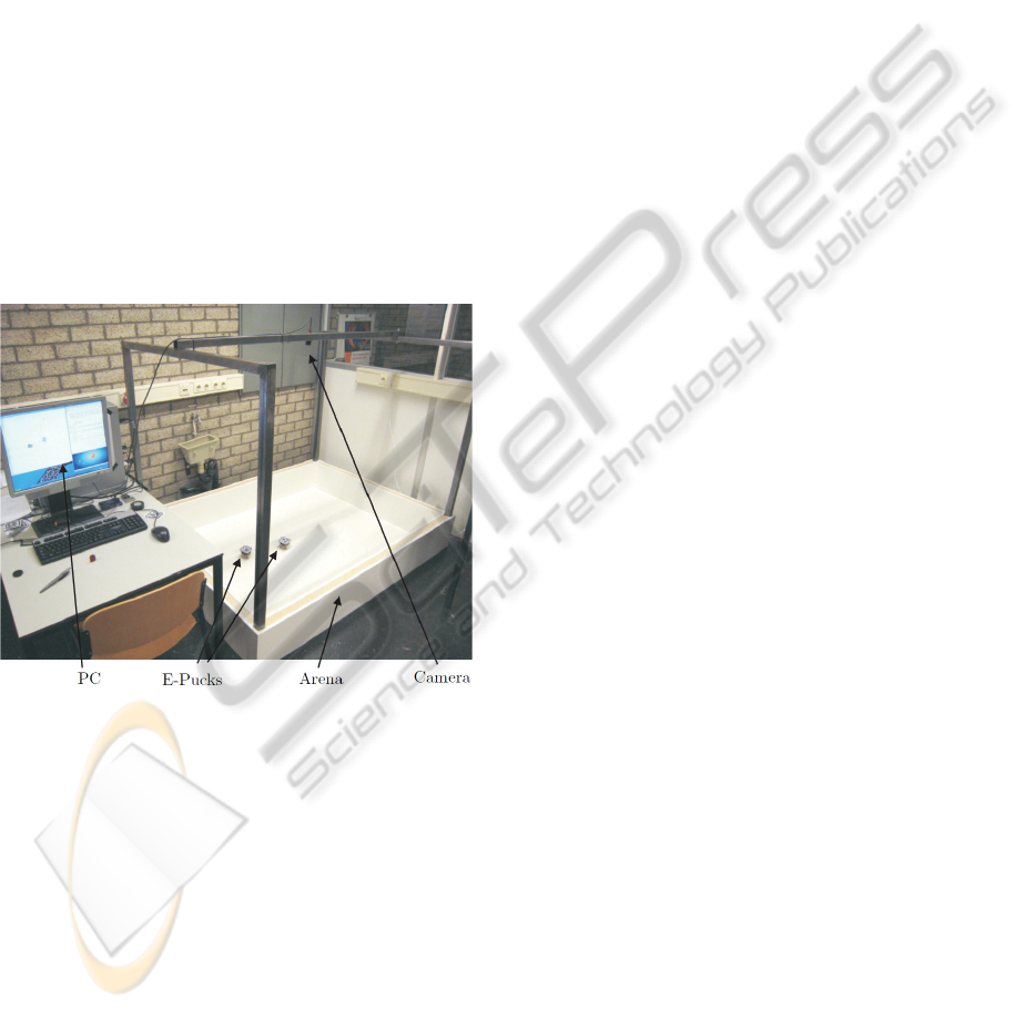
4.1 Experimental Platform Description
The experimental platforms’ design objectives
encompass cost, reliability and flexibility. The
hardware and software choices together with the
implementation of the setup at TU/e are discussed
in greater detail in (van den Broek, 2008) (cf. Fig.
3). The setup has already been used to implement
cooperation, coordination, collision avoidance and
servo vision algorithms. The platform at TMU has
similar characteristics, only differing from the one at
TU/e in its size and vision calibration algorithm.
i
i
“fig˙setup˙temp” — 2009/9/16 — 10:26 — page 1 — #1
i
i
i
i
i
i
Figure 3: Experimental setup at TU/e.
Mobile Robot. The unicycle selected is the e-puck,
(Mondada et al., 2009), whose wheels are driven
by stepper motors that receive velocity control com-
mands over a BlueTooth connection.
Vision. Each robot is fitted with a fiducial marker of
7 by 7 cm, collected by an industrial FireWire cam-
era, interpreted in the program reacTIVision (reac-
TIVision, 2009), and calibrated by means of a global
transformation (TU/e) or a grid (TMU).
Driving Area. The driving area is of 175 × 128 cm
for TU/e and 100×50 cm for TMU, and is determined
based on the required accuracy, the camera lens, and
the height at which the camera is positioned.
Software. The e-puck robots and reacTIVision’s
data stream can be managed in C, Python, or Mat-
lab script. In this work, the controller implementa-
tion and signal processing is carried out in Python,
(Python, 2009).
Bandwidth and Sampling Rate. Using vision as
the localization technique diminishes the system’s
bandwidth and results in a sampling rate of 25Hz.
4.2 Data Exchange over the Internet
Due to its widespread availability and low cost, the
Internet is chosen as the communication channel to
exchange data between TU/e and TMU.
Data Exchange. A Virtual Private Network (VPN)
is established between TU/e and TMU in order to
implement a reliable and secure data exchange.
Socket Configuration. Data is exchanged between
TU/e and TMU as soon as it becomes available
using non-blocking Transmission Control Protocol
(TCP) sockets running the Internet Protocol (IP). The
system’s low bandwidth allows the use of the TCP,
which guarantees reliable and orderly data delivery.
Data Payload. The variables exchanged amount to
the current time instant and control signals from the
control side to the system, and to the position and ori-
entation values from the system side to the controller.
4.3 Implementation Issues
One of the main implementation issues of the
proposed time-delay compensation strategy is the
accurate modeling and characterization of the
time-delay induced by the communication chan-
nel. The use of predictor-like schemes is often
discouraged because of their sensitivity to delay
model mismatches, (Hokayem and Spong, 2006),
specially when considering nonlinear systems and a
communication channel such as the Internet. To this
end, three methods that ease the implementation of
the proposed compensation strategy are suggested.
Their objective it to bring
˜
τ as close as possible to
τ in practice.
Delay Measurement. The round trip delay between
TU/e and TMU (and viceversa) has been measured
during different times of the day, for a variable
amount of time, and for a total time of around 60min.
The mean delay value is approximately 265ms for
ICINCO 2010 - 7th International Conference on Informatics in Control, Automation and Robotics
60
i
i
“fig˙pred˙bi˙no˙model˙temp” — 2010/2/3 — 0:52 — page 1 — #1
i
i
i
i
i
i
Communication
channel
Reference
Trajectory
Controller
Mobile
Robot
State
Predictor
Correcting
Term
Forward
time-delay
Backward
time-delay
r
q
u
u
τ
v
z
q
q
τ
2
z
τ
Figure 4: Time-delay compensation scheme block diagram
representation without time-delay models.
both cases (267.4917ms TU/e-TMU, 269.5307ms
TMU-TU/e). Occurrences of delays greater than
300ms where of 0.27% for TU/e-TMU and 0.34%
for TMU-TU/e. Thus, the round trip delay can be
modeled with enough accuracy even if the Internet is
considered as the communication channel.
Time-stamping. Outgoing and incoming data on
the controller side can be time-stamped in order to
estimate the round trip delay for each pair of control
signals and sensor data, setting the estimator’s delay
model accordingly.
Signal Bouncing. The estimator’s output may be
sent together with the control signals to the mobile
robot, and then sent back to the controller without
being modified. By using the communication chan-
nel itself to delay the estimator’s output, modeling the
time-delay is no longer necessary (cf. Figure 4).
4.4 Experiments
In the first experiment a mobile robot at TMU is
controlled from TU/e. The reference trajectory is a
lemniscate with center at [0.5m, 0.25m], a length and
width of 0.2m, and a velocity multiplier of 0.2m/s.
The scenario repeats in the second experiment, where
a sinusoid with origin at [0.1m, 0.25m], an amplitude
of 0.15m, an angular frequency of 0.3rad/s, and a ve-
locity multiplier of 0.01m/s constitutes the reference.
The system’s initial condition is q(0) =
[0.3235m 0.1882m 0.2851rad]
T
for the first ex-
periment and q(0) = [0.0225m 0.1821m 0.3916rad]
T
for the second one. In both cases the estimator’s
initial condition is set to z(0) = [0 0 0]
T
, the controller
gains to c
1
= 1.0, c
2
= c
3
= 2.0 and the correcting
term gains to K
x
= K
y
= K
θ
= −0.6. The sampling
rate is 25Hz and the experiments’ duration is 60sec
and 120sec respectively. The round trip delay is
modeled as 265ms based on measurements, although
the estimator’s output is in fact delayed 280ms since
0 0.2 0.4 0.6
0
0.1
0.2
0.3
0.4
0.5
0.6
X [m]
Y [m]
0 0.5 1
0
0.1
0.2
0.3
0.4
0.5
X [m]
Y [m]
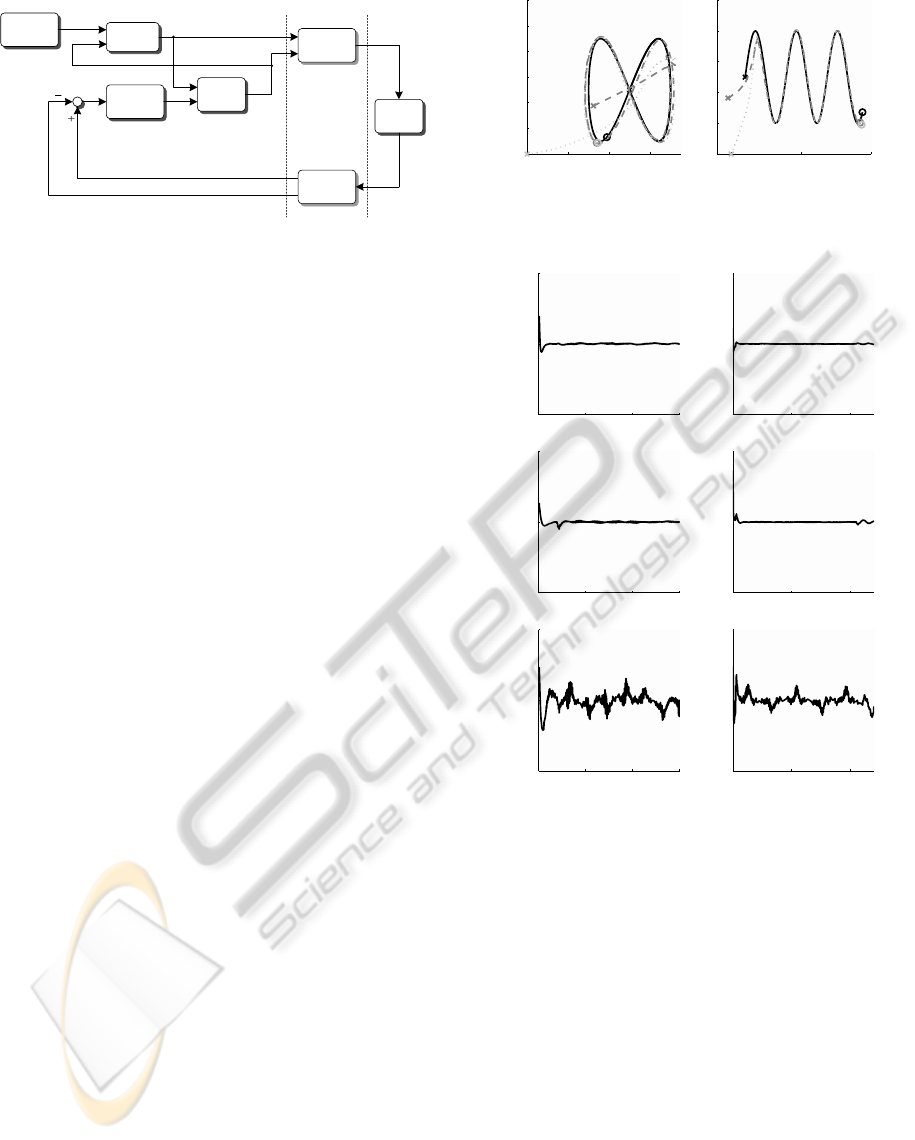
Figure 5: Reference, robot and predictor behavior in the X-
Y plane for two different trajectories.
0 20 40 60
−0.5
0
0.5
t [s]
ν
x
[m]
0 20 40 60
−0.5
0
0.5
t [s]
ν
y
[m]
0 20 40 60
−0.5
0
0.5
t [s]
ν
θ
[rad]
0 50 100
−0.5
0
0.5
t [s]
ν
x
[m]
0 50 100
−0.5
0
0.5
t [s]
ν
y
[m]
0 50 100
−0.5
0
0.5
t [s]
ν
θ
[rad]
Figure 6: Practical convergence of the correcting terms.
only delay models which are multiples of 0.04 are
allowed due to the setup’s sampling time, meaning
data is displaced 7 locations within the storage buffer.
The experimental results are shown in Figure 5
and 6 for both experiments. The first plots show the
reference (black), robot (gray) and predictor (light
gray) trajectories in the X-Y plane, with their initial
and final position marked with a cross and a circle
respectively. The plots in Figure 6 show the evolution
of the correcting terms ν
x
(t), ν
y
(t), and ν
θ
(t) and how
they practically converge to zero even in the presence
of a delay model mismatch and considering a time-
varying communication channel. The behavior of the
proposed delay compensation strategy is consistent
with the stability analysis presented and the tracking
performance of the robot can be ensured even under a
bilateral time-delay.
REMOTE CONTROL OF A MOBILE ROBOT SUBJECT TO A COMMUNICATION DELAY
61

5 DISCUSSION
A compensation strategy to account for the negative
effects of a bilateral time-delay affecting a unicycle-
type mobile robot has been proposed. Several tech-
niques to accurately reproduce the time-delay in the
estimator have been presented, since this is required
and often a cause of concern in predictor-like control
strategies. Experiments show that the delay compen-
sation strategy is robust to small delay model mis-
matches and delay variations using the Internet as a
communication channel.
Future work includes a robustness analysis of
the delay compensation scheme and a comparison
with other predictor-like strategies. Additionally,
techniques to synchronize as precisely as possible
the controller and system sides are being studied in
order to obtain a more accurate measurement of the
system’s performance. Integrating the concept of
remote control of mobile robots with notions related
to the long distance synchronization of robotic net-
works and extending the concepts of the estimator to a
more general setting (other mechanical systems) also
remain topics to be addressed in the future.
ACKNOWLEDGEMENTS
The first author would like to dedicate this paper to
his father, Prof. Jaime Alvarez-Gallegos of CINVES-
TAV, M
´
exico, who was recently honored because of
his 60th birthday. Additionally, the authors acknowl-
edge the help of Hisashi Katsumata in conducting ex-
periments. This work has been supported by CONA-
CYT and SEP, M
´
exico, by the Graduate School of
Science and Engineering at TMU and the Japan So-
ciety for the Promotion of Science (JSPS) through
Grant-in-Aid for Scientific Research (No. 20560424).
REFERENCES
Brockett, R. (1983). Differential geometric control theory,
chapter Asymptotic stability and feedback stabiliza-
tion, pages 181–191. Birkh
¨
auser.
Heemels, W. P. M. H., Teel, A. R., van de Wouw, N., and
Nesic, D. (2010). Networked control systems with
communication constraints: Tradeoffs between sam-
pling intervals, delays and performance. IEEE Trans.
Automat. Contr., Accepted.
Hokayem, P. F. and Spong, M. W. (2006). Bilateral
teleoperation: An historial survey. Automatica,
42(12):2035–2057.
Jakubiak, J., Lefeber, E., Tch
´
on, K., and Nijmeijer, H.
(2002). Two observer-based tracking algorithms for
a unicycle mobile robot. Int. J. Appl. Math. Comput.
Sci., 12(4):513–522.
Kanayama, Y., Kimura, Y., Miyazaki, F., and Noguchi, T.
(1990). A stable tracking control method for an au-
tonomous mobile robot. In Proc. IEEE Int. Conf. Rob.
Automat. (ICRA), pages 384–389.
Kojima, K., Oguchi, T., Alvarez-Aguirre, A., and Nijmeijer,
H. (2010). Predictor-based tracking control of a mo-
bile robot with time-delays. In Proc. 8th IFAC Sympo-
sium on Nonlinear Control Systems (NOLCOS). (Ac-
cepted).
Kostic, D., Adinandra, S., Caarls, J., van de Wouw, N., and
Nijmeijer, H. (2009). Collision-free tracking control
of unicycle mobile robots. In Proc. 48th IEEE Conf.
Dec. Control (CDC/CCC), pages 5667–5672.
Mondada, F., Bonani, M., Raemy, X., Pugh, J., Cianci, C.,
Klaptocz, A., Magnenat, S., Zufferey, J.-C., Floreano,
D., and Martinoli, A. (2009). The e-puck, a robot de-
signed for education in engineering. In Proc. 9th Con-
ference on Autonomous Robot Systems and Competi-
tions, pages 59–65.
Niemeyer, G., Preusche, C., and Hirzinger, G. (2008).
Springer Handbook of Robotics, chapter 31: Teler-
obotics, pages 741–758. Springer-Verlag.
Oguchi, T. and Nijmeijer, H. (2005a). Control of nonlinear
systems with time-delay using state prediction based
on synchronization. In Proc. EUROMECH Nonlinear
Dynamics Conference (ENOC), pages 1150–1156.
Oguchi, T. and Nijmeijer, H. (2005b). Prediction of
chaotic behavior. IEEE Trans. on Circ. and Syst. I,
52(11):2464–2472.
Oguchi, T. and Nijmeijer, H. (2006). Anticipating synchro-
nization of nonlinear systems with uncertainties. In
6th IFAC Workschop on Time-Delay Systems.
Panteley, E., Lefeber, E., Lor
´
ıa, A., and Nijmeijer, H.
(1998). Exponential tracking control of a mobile car
using a cascaded approach. In IFAC Workshop on Mo-
tion Control.
Panteley, E. and Lor
´
ıa, A. (1998). On global uniform
asymptotic stability of nonlinear time-varying systems
in cascade. Syst. Contr. Lett., 33(2):131–138.
Python (2009). Python Programming Language.
http://www.python.org.
reacTIVision (2009). reacTIVision 1.4: A
toolkit for tangible multi-touch surfaces.
http://reactivision.sourceforge.net/.
Tipsuwan, Y. and Chow, M.-Y. (2003). Control methodolo-
gies in networked control systems. Contr. Eng. Pract.,
11(10):1099–1111.
van den Broek, T. (2008). Formation Control of Unicycle
Mobile Robots: Theory and Experiments. Master’s
thesis, Eindhoven University of Technology.
van den Broek, T., van de Wouw, N., and Nijmeijer, H.
(2009). Formation control of unicycle mobile robots:
A virtual structure approach. In Proc. 48th IEEE Conf.
Dec. Control (CDC/CCC), pages 3264–3269.
Voss, H. U. (2000). Anticipating chaotic synchronization.
Phys. Rev., 61(15):5115–5119.
ICINCO 2010 - 7th International Conference on Informatics in Control, Automation and Robotics
62
