DEVELOPMENT OF LIGHTWEIGHT DUAL ARM ROBOT BY
USING HOLLOW SHAFT SERVO ASSEMBLY
Min-Kyu Park
Division of Mechanical Engineering, Yeungnam College of Science & Technology
274 Hyeungchungro, Deagu, South Korea
Seok-Jo Go
Division of Mechanical Engineering, Dongeui Institute of Technology, 152 Yangjiro, Pusan, South Korea
Young-Jin Lee
Autopower Co. LTD., 1048-9 Obang-dong, Kimhae, Kyungnam, South Korea
Keywords: AUTOMAN, Dual Arm Robot, Hollow Shaft Servo Assembly, Lightweight Robot Arm.
Abstract: Studies on dual arm robots have been continually carried out because the robots provide human-like
flexibility of movement. In previous study, the dual arm robot with solid shafts had been designed.
However, the robot has some defects in its heavy weight and big shape. In this study, a hollow shaft servo
assembly for lightweight robot arm has been developed. And then, the dual arm robot (AUTOMAN) has
been designed using a hollow shaft servo assembly.
1 INTRODUCTION
Single arm industrial robots are applied in the
process where the simple repetitive operation is
much like the automotive industry and the
semiconductor industry. There are many tasks that
are difficult or impossible to do with the single arm
robots. The dual arm robot is able to solve these
problems (University of Texas at Austin, DLR,
Yaskawa Co.). In the previous study, the dual arm
robot with solid shafts had been developed as shown
in Figure 1 (Park, 2008). The robot with solid shafts
is easily implemented. However, as the degree of
freedom of a robot rises, when implementing the
complicated motion, some problems are appeared
such as kink and abrasion of cables. As to the dual
arm robot with hollow shafts, the inside of an arm
and a motor shaft are empty. It is free from a
constraint by the electrical wire in the
implementation of complicated motion in
comparison with the robot with solid shafts (Han,
2008). Also, the load to weight ratio of a robot is
improved. Accordingly, basic researches on the
hollow shaft servo assembly had been carried out in
the previous studies (Han, 2008; Lee, 2008; Go.
2009).
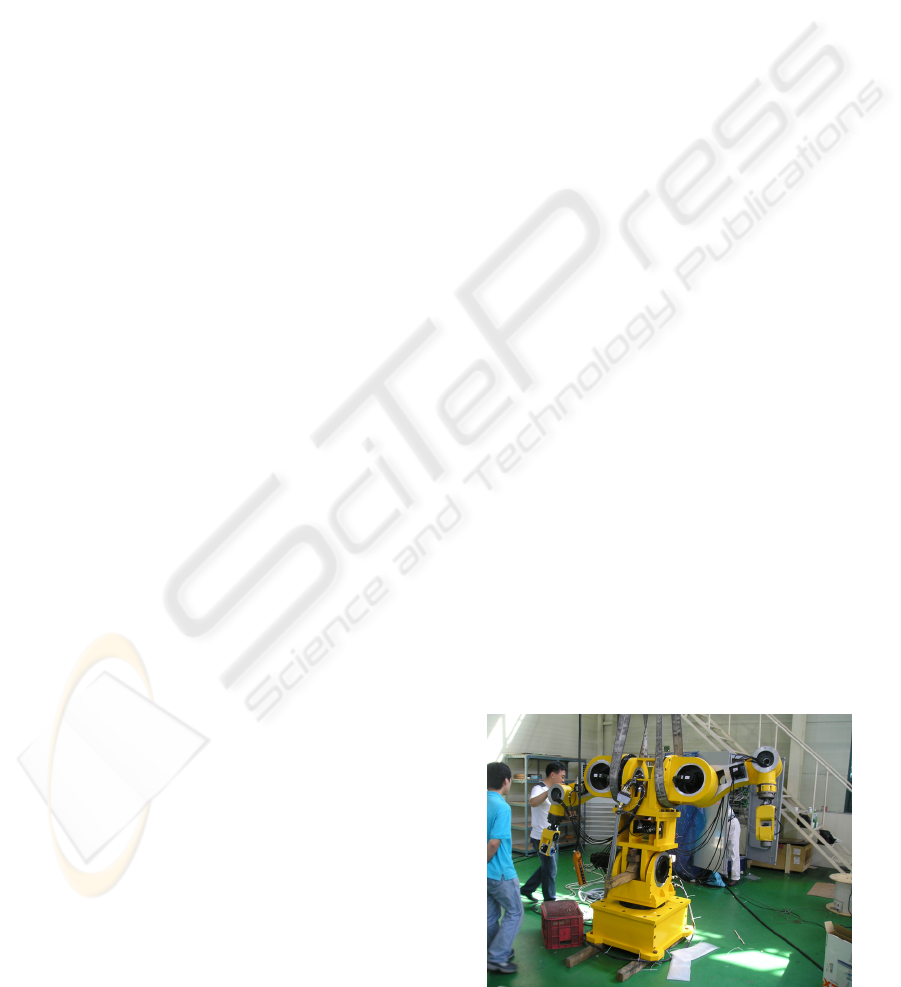
The goal of this study is to develop a dual arm
robot with the hollow shaft servo assembly. Firstly,
the hollow shaft servo assembly for applying to the
dual arm robot is developed. Secondly, the
performance of the completed servo assembly is
evaluated. Finally, the industrial hollow shaft
articulated dual arm robot (called as AUTOMAN)
tries to be developed.
Figure 1: Dual arm robot developed in previous study.
409
Park M., Go S. and Lee Y. (2010).
DEVELOPMENT OF LIGHTWEIGHT DUAL ARM ROBOT BY USING HOLLOW SHAFT SERVO ASSEMBLY.
In Proceedings of the 7th International Conference on Informatics in Control, Automation and Robotics, pages 409-414
DOI: 10.5220/0002944304090414
Copyright
c
SciTePress
2 HOLLOW SHAFT SERVO
ASSEMBLY
In order to apply hollow shaft to industrial dual arm,
the specifications of each axis have to be
determined. The payload of the robot is set as 20kg.
The specifications of the each hollow shaft servo
assembly are determined by analyzing the maximum
torque and the steady state torque under tracking
trajectories at full reach within given time like
Figure 2. The capacity, torque and maximum
velocity of each axis are finally obtained by
applying a safety factor to analyzing value as shown
in Table 1 (Lee, 2008).
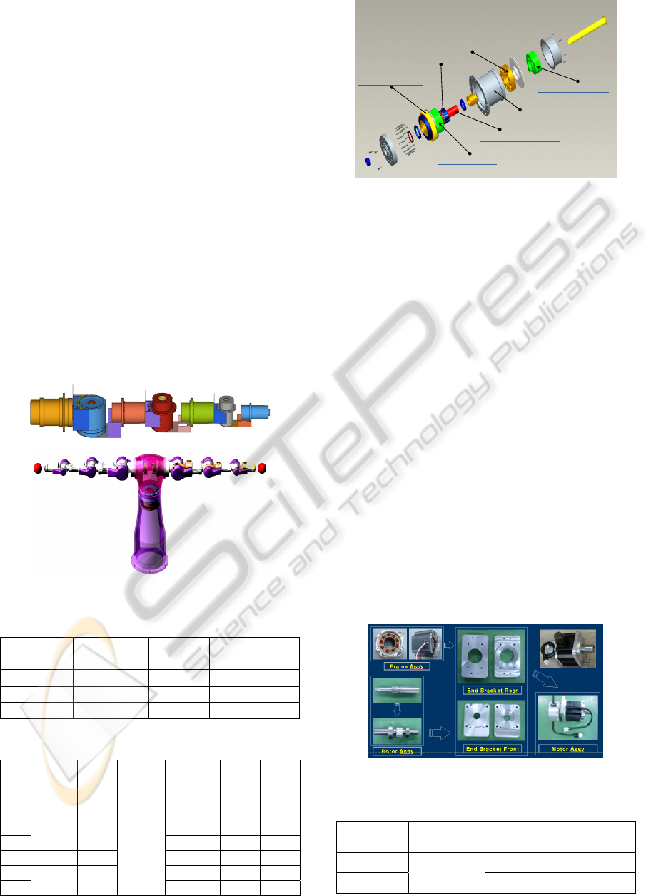
The assembly drawing of the hollow shaft servo
assembly for the dual arm robot is shown in Figure 3.
The key components comprising the servo assembly
are the hollow shaft servo motor, the hollow shaft
multi-turn absolute encoder, the hollow shaft brake,
and, the hollow shaft harmonic drive. Table 2 shows
the axis specification of the developed hollow shaft
servo assembly.
Figure 2: Dynamic critical conditions of dual arm robot.
Table 1: Specifications of servo motors.
Axis Capacity Torque Velocity
1, 2 2.0 kW 6.8 Nm 3,000 RPM
3, 4 0.9 kW 2.9 Nm 3,000 RPM
5 0.6 kW 1.9 Nm 3,000 RPM
6, 7 0.4 kW 1.3 Nm 3,000 RPM
Table 2: Specifications of hollow shaft servo assembly.
Axis
Capacity
[kW]
Torque
[Nm]
Velocity
[rpm]
Reduction
gear ratio
Weight
[kg]
Length
[mm]
1
2.0 6.8
3,000
120 23.5 270
2 120 23.9 270
3
0.9 2.9
120 11.6 236
4 120 12.5 236
5 0.6 1.9 80 5.1 237
6
0.4 1.3
80 4.9 213
7 80 4.3 213
harmonic drive
rotor
stator
electric brake
absolute encoder
hollow shaft motor
frame
harmonic drive
rotor
stator
electric brake
absolute encoder
hollow shaft motor
frame
Figure 3: Hollow shaft servo assembly.
2.1 Hollow Shaft Servo Motor
As to the development of the hollow shaft servo
motor, because all cables enter into the hollow shaft,
the inner diameter of hollow shaft is as big as
possible and it should not have a problem in an
assembly between the hollow shaft encoder and the
hollow shaft brake. Moreover, because the hollow
shaft rotates, the protecting duct in which it protects
the cable has to be installed and the axis of motor
has to be designed by considering the connection
with the axis of a reduction gear.
Accordingly, the hollow shaft servo motor was
developed in consideration of the hollow size and
the axis capacity of the motor. Figure 4 shows the
developed hollow shaft servo motor. The cores of
stator and rotor used the Si-steel S18 and S30
respectively. And the magnets of these used Nd-Fe-
B and N-35SH.
Since being the servo system, sensors such as a
resolver or a hollow shaft absolute encoder is
essential. Accordingly, the hollow shaft absolute
encoder is selected as shown in Table 3 (Tamagawa
Seiki Co.).
Figure 4: Hollow shaft servo motor.
Table 3: Specifications of applied encoder.
Axis
Resolution
[bit]
Revolution
[RPM]
Weight
[kg]
1,2
33
1,500 2.1
3~7 3,000 1.2
ICINCO 2010 - 7th International Conference on Informatics in Control, Automation and Robotics
410
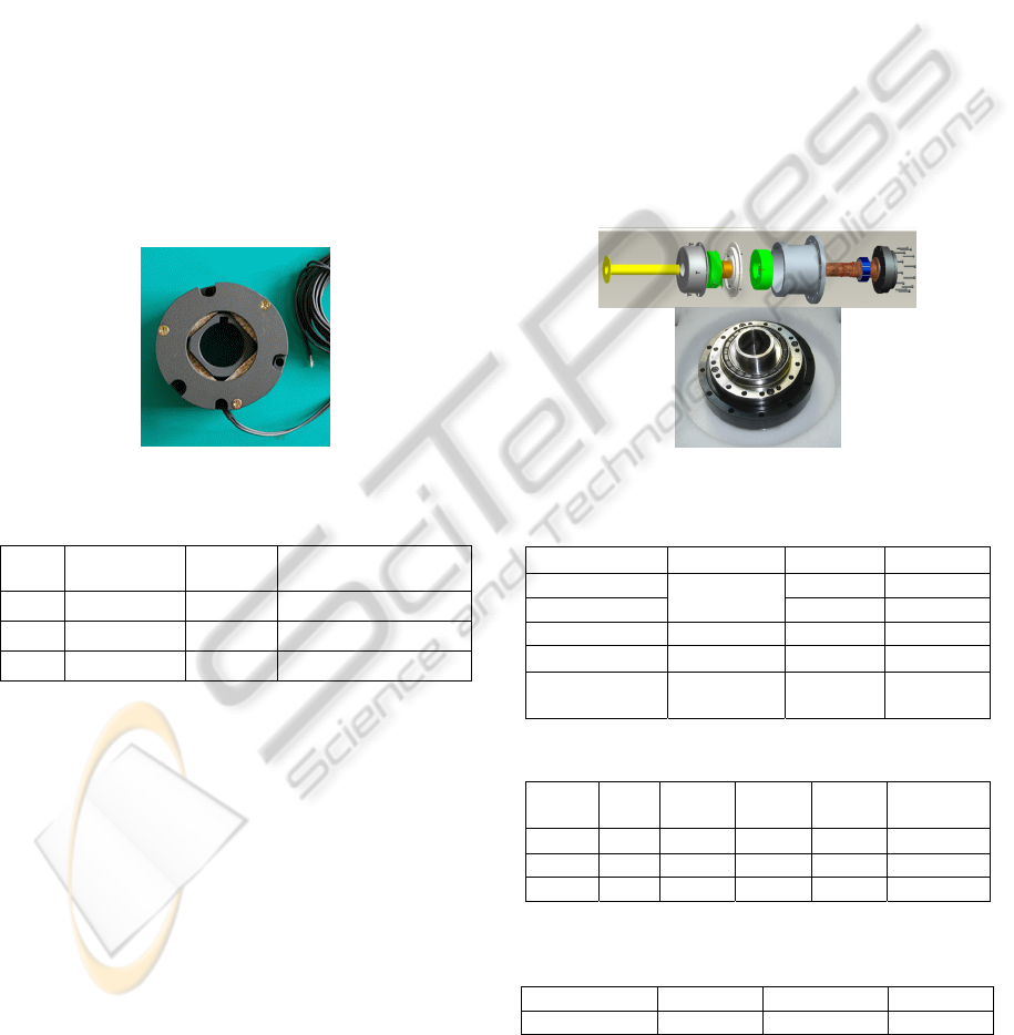
2.2 Hollow Shaft Brake
The development of the hub shape type brake is
needed, because the hollow shaft of the servo motor
can be penetrated. The excitation functional type
brake stops a rotator when a current is electrified in
a coil. Therefore, this brake is suitable to the
machine with horizontal motion. On the other hand,
as to the electro-magnetic operable brake, when a
current is electrified in a coil, the braking power
loses and a rotator is free. This type brake is usually
applied by the machines with vertical motion. In this
research, since the vertical motion had to be possible
in the small and narrow place, the hollow shaft brake
of the non-excited operation type is developed by
considering the required torque and dimension of
each axis. Figure 5 shows the developed hollow
shaft brake and the specifications are shown in Table
4.
Figure 5: Hollow shaft brake.
Table 4: Specifications of developed hollow brake.
Axis
Frictional
Tor
q
ue
[
Nm
]
Weight
[
k
g]
Outer Dia. / Inner
Dia. / Thickness
1,2 6.86 2.77 147 / 51 / 38.3
3,4 2.94 1.18 104 / 41 / 36/2
5,6,7 2.45 0.54 74.8 / 26 / 29/8
2.3 Hollow Shaft Harmonic Drive Unit
The reduction gear applied to the dual arm robot has
to be fitted the hole size of the hollow. And not only
the high-torque and but also the high precision are
needed. The hollow shaft harmonic drive made by
Harmonic Driver Systems in Japan is applied
(Samick HDS). The motor shaft and the axis of
reduction gear are connected as shown in Figure 6.
The test results of eccentricity and torsion stress are
satisfied the required specifications as shown in
Table 5. The specifications of developed hollow
shaft harmonic drive are presented by Table 6.
2.4 Performance Test of Hollow Shaft
Servo Assembly
After making one side of the dual arm robot as
Figure 7, the test of repeatability carried out. Table 7
shows the specifications of the developed hollow
shaft robot arm. In the performance evaluation about
the robot arm, the repetition precision about the
location tracking was verified according to the KS
7082 standard (KS B 7082,) After from P1 to P5
designated the coordinate in which a robot has to
follow according to the three-dimensional space-
phase like Figure 8, the repetition tracking was
performed by 30 time series. The laser tracker was
used to measure the positions. Results of
repeatability test are as shown in Figure 9. The
average repeatability about each site is ± 0.05 mm
within and it is satisfactory.
Figure 6: Hollow shaft harmonic drive.
Table 5: Performance test results of the unit.
Spec. Test 1 Test 2
Concentricity1
0.02 and
less
0.0103 0.0122
Concentricity2 0.0047 0.0185
Diameter[mm] 50 + 0.015 50.0144 49.9985
Length[mm]
300±0.3
300.0625 300.1394
Torque[Nm]
More than
4.7
274.5 246.37
Table 6: Specifications of the hollow harmonic drive.
Axis Ratio
Torque
[Nm]
Speed
[RPM]
Weight
[kg]
Outer/Inner
[mm]
1,2 120 523 3,000 6.9 190 / 52
3,4 120 178 3,000 3.1 142 / 36
5,6,7 80 44 3,000 0.89 90 / 21
Table 7: Specifications of developed hollow Shaft robot
arm.
Weight Length Payload
Specification 94kg 1,574mm 20kg
DEVELOPMENT OF LIGHTWEIGHT DUAL ARM ROBOT BY USING HOLLOW SHAFT SERVO ASSEMBLY
411
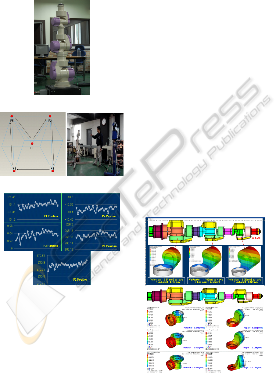
Figure 7: Developed hollow-type robot arm.
Figure 8: Reference trajectory.
Figure 9: Results of repeatability test. [unit : mm].
3
DESIGN OF DUAL ARM ROBOT
In the previous research, the solid type dual arm
robot like Figure 1 had been developed (Park, 2008).
The dual arm robot developed in the previous
research has the both arms of 6 degree of freedoms
with the payload 20 kg, and the body (torso) of 2
degree of freedom. However, as to the developed
dual arm robot, some problems have occurred such
as the overweight compared with payload, the
increase of the servo motor capacity due to a volume
and weight enlargement, a kick and an abrasion of
cables. In order to solve these problems, the hollow
shaft servo assembly is developed. In the
development of the robot, it tried to lighten through
the stress analysis and optimal design. The servo
control systems like servo drivers and controller are
used by commercial controller.
3.1 Design and Fabrication of Robot
The dual arm robot makes to put an emphasis on the
improvement of the weight and movement. Housing,
frame, cover and the key element parts of robot are
developed by considering the design specifications
as shown in Figure 10. Especially, in the case of the
housing, in order to satisfy the maximum allowable
deflection 3 mm at full reach of the horizontal
direction, the target rigidity is obtained by the CAE
analysis (Lee, 2008). Figure 11 shows the dual arm
robot (AUTOMAN) in which it makes in this
research. It can show the reduction of weight and the
improvement of design. AUTOMAN is composed of
two arms and one twist joint. Each arm has 7 DOF.
Therefore, AUTOMAN totally has 15 DOF. The
robot can be designed so that cables can pass
through the central part of a robot. The length of the
arm is about 1,500 mm. Table 8 shows the
specification comparison with the solid type dual
arm robot.
Figure 10: Design of motor frame and housing.
ICINCO 2010 - 7th International Conference on Informatics in Control, Automation and Robotics
412
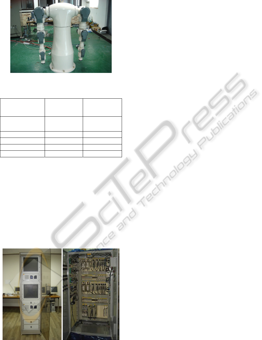
Figure 11: AUTOMAN.
Table 8: Specifications of developed dual arm robot.
Item
Solid type dual
arm robot (Fig. 1)
AUTOMAN
Controlled axes
14(Right 6, left 6,
rotate 2)
15(Right 7, left 7,
rotate 1)
Payload 20 kg 20 kg
Mass 500 kg 300 kg
Repeatability ±0.7 mm ±0.1 mm
Maximum Speed 100 °/s 100 °/s
3.2 Development of Control System
The robot control system is designed for considering
convenience of developing environment, powerful
computing, real-time operation ability. Figure 12
shows the control system of the robot. The MEI
ZMP controller (The Motion Engineering) and
PMAC controller (DELTA TAU) were examined in
order to select the controller in which it is suitable
for the dual arm robot (MEL, DELTA TAU). It is
altogether able to use with these controllers in case
the moving track of a robot is predetermined.
Figure 12: Control system of AUTOMAN.
However PMAC controller has evaluated that it
could not be guaranteed a real-time ability in case
the moving track of a robot is determined in real
time such as a visual servoing control and a force
control. Accordingly, in order that the target
platform of the control system was determined, the
ZMP board (DELTA TAU), that is the commercial
controller in which a performance is verified, was
selected as the controller of the dual arm robot.
4 CONCLUSIONS
This research tried to be comprised the light weight
of the dual arm robot by the hollow shaft servo
assembly, and a miniaturization and highly-rigid in
order to solve a problems reflected in the previous
developed dual arm robot. The hollow shaft servo
assembly is developed by designing and fabricating
the hollow shaft servo motor, the hollow shaft brake,
and so on. And the dual arm robot (AUTOMAN) for
the flexible package operation is designed and made.
The control system is made in consideration of a
convenience and operation processing speed of the
development environment. The performance of the
arm is confirmed that the average repeatability is
measured by ± 0.05 mm within and it is satisfactory.
Moreover, by installing in the cable, kink and
friction problems were solved. It is finally remarked
that the comparison between the solid type robot and
the developed hollow type robot will be undertaken
as a second phase of this work.
ACKNOWLEDGEMENTS
This work was supported by the Ministry of
Commerce, Industry and Energy under Grant No.
10025003.
REFERENCES
University of Texas at Austin, http://www.robotics.
utexas.edu/rrg/.
DLR, http://www.dlr.de/en/.
Yaskawa Inc., http://www.motoman.com/.
Park, C. H., Park K. T., and Kim, D. H., “Design of dual
arm robot manipulator for precision assembly of
mechanical parts,” 2008 International Conference on
Smart Manufacturing Application, pp. 424-427, April
2008.
Han, H. G., Go, H. Y., Lee, Y. C., Jung, C. G., Shin, Y. S.,
Go, S. J., and Lee, Y. J., “Development of Hallow
DEVELOPMENT OF LIGHTWEIGHT DUAL ARM ROBOT BY USING HOLLOW SHAFT SERVO ASSEMBLY
413

Shaft Servo Assembly for Light Weight Robot,”
Control, Automation, and Systems Symposium 2008,
pp. 403-406, October 2008.
Lee, J. W., Han, H. G., Jung, S. W., Yoo, W. S., and Lee,
Y. J., “Design of Dual-Arm Robot Using CAE
Techniques,” Control, Automation, and Systems
Symposium 2008, pp. 407-410, October 2008.
Go, S. J., Han, H. G., Go, H. Y., Lee, Y. C., Jung, C. G.,
Shin, Y. S., and Lee, Y. J., “Development of Hallow
Shaft Servo Assembly for Dual Arm Robot and Its
Performance Evaluation,” KACC 2009, pp. 58-61,
September 2009.
Samick HDS, http://www.samickhds.co.kr.
Tamagawa Seiki, http://tamagawa-seiki.com.
KS B 7082, ISO9283, Manipulating industrial robots:
Performance criteria and related test methods.
MEI, Inc., Product Manual.
DELTA TAU Data Systems, Inc., Product Manual.
ICINCO 2010 - 7th International Conference on Informatics in Control, Automation and Robotics
414
