
LOCALIZATION IN AN AUTONOMOUS UNDERWATER
MULTI-ROBOT SYSTEM DESIGNED FOR COASTAL AREA
MONITORING
Zhongliang Hu, Eemeli Aro, Tapani Stipa†, Mika Vainio and Aarne Halme
Finnish Center of Excellence in Generic Intelligent Machines Research, Aalto University School of Science and Technology
P.O. Box 15500, FI-00076 Aalto, Finland
†Marine Hydrodynamics, Finnish Meteorological Institute, Erik Palmenin aukio 1, P.O. Box 50, FI-00101, Helsinki, Finland
Keywords:
Multi-robotic system, Autonomous underwater localization, Underwater acoustic communication, Coastal
area monitoring.
Abstract:
In this paper we present an multi-robotic system for underwater exploration, specifically for coastal seas.
The novelty of this system is its enhanced performance in underwater localization using underwater acoustic
ranging and data transfer between the floats. This process is not dependent on any fixed infrastructure, which is
usually a requirement for such missions. An algorithm is implemented in the floats for underwater localization,
based on an Extended Kalman Filter. Extensive real scenario simulation test results are presented.
1 INTRODUCTION
The value of services provided by the coastal seas, in-
cluding estuaries, to the human welfare is estimated
to be higher than those of terrestrial or open ocean
systems (Costanza et al., 1998). The relevant spatial
and seasonal scales for biological variability are of-
ten related to hydrophysical events; these are mostly
unpredictable and practically impossible to cover by
traditional monitoring with sparse sampling.
Autonomous underwater multi-probe system for
coastal area / shallow water monitoring (SWARM)
was an EU-funded (FP5, 2003-2005) project aiming
to design, implement and test a multi-robot system
that could measure local and transient biological and
physical variability in the Baltic Sea and similar areas
at the scale relevant for single events.
Based on the initial ideas and hardware designed
and built during the SWARM project, the Finnish
Center of Excellence in Generic Intelligent Machines
(GIM) has continued the related research. As one of
the results, a localization method has been developed
that requires no additional infrastructure, fixed bea-
cons or expensive inertial units, while producing ac-
curate real-time location estimates for the members
of the system. The method is based solely on un-
derwater inter-robot acoustic communication and oc-
casional GPS fixes while on the surface. It is worth
mentioning that the internal intelligence which is es-
sential for the units to navigate and survive in the dy-
namic and hostile underwater environment makes the
units stand out from mere buoyancy floats to intelli-
gent underwater robots.
In this paper, the main features of this system
working in an extremely challenging environment
will be first briefly introduced. Then, the main topic
of this paper, i.e., a novel localization approach will
be presented and verified with suitable tests. Finally,
some conclusions are drawn and some information re-
garding the future work will be presented.
2 SYSTEM DESCRIPTION
The scientific objective of the SWARM project was
to design, implement and test a novel highly redun-
dant underwater monitoring system for shallow water
areas (Vainio et al., 2004). The system consists of
multiple homogenous, robust and easy to use under-
water robots (autonomous intelligent profiling floats)
that can perform two week missions autonomously.
The floats control their buoyancy but move otherwise
freely with the water flows. They communicate with
the control station via Iridium satellite communica-
tion and use inter-robot acoustic ranging and commu-
nication for localization and data exchange. In addi-
tion to measuring the standard variables (pressure,
232
Hu Z., Aro E., Stipa T., Vainio M. and Halme A. (2010).
LOCALIZATION IN AN AUTONOMOUS UNDERWATER MULTI-ROBOT SYSTEM DESIGNED FOR COASTAL AREA MONITORING.
In Proceedings of the 7th International Conference on Informatics in Control, Automation and Robotics, pages 232-239
DOI: 10.5220/0002945502320239
Copyright
c
SciTePress
temperature, conductivity), the system observes cer-
tain algal groups with a novel fluorometer.
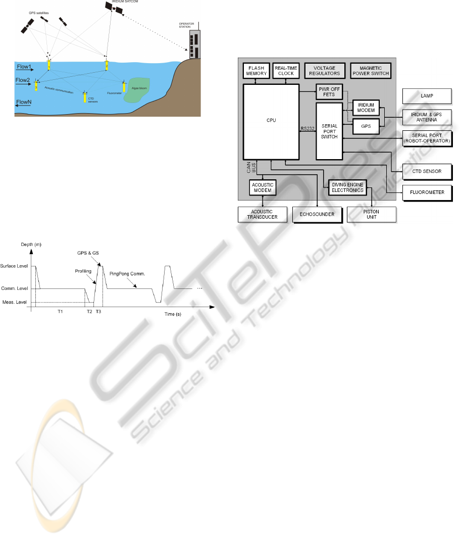
Figure 1: The general description of the SWARM system.
The diving profile of the floats was selected based
on two main issues: to enable the system to measure
the key environmental parameters from the main ar-
eas of interest and to support the proposed localiza-
tion method. It also matches the standard profile used
by Argo floats globally, but of course with shallower
depths (Davis et al., 2001).
Figure 2: Diving profile of a unit.
T1: Waiting time. The float spends most of its
time waiting on this level. The benefit of this is such
that the float does not need to stay on the surface all
the time but by taking advantage of communication it
can still keep a track of its location during the mission.
T2: Diving time. When T1 expires, the float will
start to dive to a deeper level and wait there for the
start of profiling.
T3: Profiling time. After T2 expires, the
floats ascents to surface, during which time it takes
CTD(conductivity, temperature and density) profile.
When the float reaches the surface, it gets a GPS
fix and contact the operator station for possible com-
mands and reports data.
3 EXPERIMENTAL SETUP
During the EU-funded phase, the functionality of
each of the subsystems were tested separately before
final integration into a prototype. Major part of these
tests were carried out in Gulf of Finland on the south
coast of Finland. In addition to the real system, a
MATLAB based simulator was designed at an early
phase of the project mainly for the testing of local-
ization algorithms. After the end of the EU funding
a more sophisticated simulator was constructed and
used for the testing presented in this paper.
Figure 3: Subsystems shown in a block diagram.
A simplified block diagram shown in Figure 3
illustrates that the developed robotic prototypes are
full-blooded autonomous profiling floats which are
equipped with extensive repertoire of environmental
sensors. Furthermore, they possess certain level of in-
telligence, which is required to survive autonomously
in a dynamic and hostile coastal waters.
3.1 Physical Realization
The main physical output of the SWARM project was
four 3
rd
generation functional floats ready for open
sea testing. These floats have since been extensively
modified and tested in the lab. Full-scale tests are ex-
pected to start from summer 2010. See Figure 4.
3.2 Simulator
A new simulator is implemented as an attempt to pro-
duce a near-realistic simulated environment for au-
tonomous floats. The simulator uses a server-client
architecture, with the environment as a server to
which each float connects. Specialized clients may
also connect to the environment to act as ground sta-
tions or data display/logging agents. Time in the sim-
ulator advances at a multiple of real time. The in-
terfaces available to a program acting as a simulated
float are modeled to match those of an actual float,
including simulated sensor errors and measurement
LOCALIZATION IN AN AUTONOMOUS UNDERWATER MULTI-ROBOT SYSTEM DESIGNED FOR COASTAL
AREA MONITORING
233
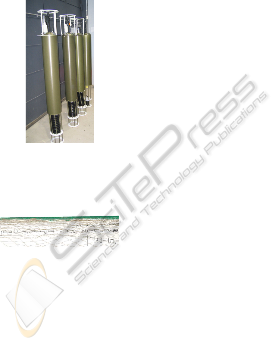
Figure 4: Available physical floats (own by SWARM con-
sortium). Floats are around 2 m tall and weigh approxi-
mately 40 kg.
time delays. This allows for hardware-in-the-loop
testing using the real float hardware, with each sen-
sor connected using a serial cable to an external com-
puter running an interface program connected to the
simulated environment.
Figure 5: Snapshot of the developed simulator.
The simulator components use GIMnet (Saarinen
et al., 2007) to communicate, allowing each program
to run on a separate networked computer if required.
The architecture is designed to scale, and can simul-
taneously model hundreds of floats at a simulation
speed far in excess of real time. The simulator can
make use of data from anywhere in the world, pro-
vided that bathymetry and three-dimensional time-
variant salinity, temperature and current vector infor-
mation is available to some precision; intermediary
values will be interpolated. The data used for the tests
presented here is from the BalEco ecosystem model
of the Finnish Institute of Marine Research (currently
Finnish Meteorological Institute).
4 FLOAT LOCALIZATION
The core element of a SWARM unit positioning sys-
tem is a GPS receiver, which is included in each of
the robots. When on the surface, a unit gets its posi-
tion from the satellites. The frequency of these GPS
fixes must be considered carefully. They will natu-
rally always bring much needed fresh and accurate
information to the system, but on the other hand, they
force the units to come to the surface which consumes
energy and increase the possibility of being hit by a
passing boat. In any case, after the GPS fix, the inter-
robot acoustic communication system between robots
is then utilized in positioning the underwater units.
It is essential to relate the measurement data that
the floats have gathered underwater with the geo-
graphical coordinates where they have been mea-
sured. A conventional float profiling operation, as
shown in Figure 2, givesreasonable results for a series
of measurement when the float comes back to the sur-
face from the deep depth, since such surfacing hap-
pens in a quite short time and the currents affecting
this movement are negligible. However, this move-
ment only gives a vertical series measurements at a
given location. We are more interested in the sea con-
ditions in a larger area, including prevailing sea cur-
rents. One approach for this can be found in (McFar-
land and Honary, 2003).
4.1 Baltic Sea
Shallow seas pose specific problems for robotic ocean
instruments. They are often strongly stratified, turbid
and have vibrant maritime activities. The bottom is
soft, to the extent that it may have adhesive powers on
instruments that land on the bottom. Figure 6 shows
an example of the complex vertical structure of tem-
perature, salinity and fluorescence, with almost unno-
ticeable physical features that nevertheless have their
impact on the biological situation.
The spatial scales of motion are often small in the
horizontal direction as well. Therefore, the state of
motion in one place is not a very good predictor of
the state some kilometers away. These factors make
it harder to observe shallow seas with robotic instru-
ments than the ocean. There should be a large number
of robotic instruments to capture the spatial variabil-
ity, yet the loss rate of robotic instruments in shallow
seas is expected to be significantly larger than in the
blue oceans, where a typical Argo float may survive
3-5 years.
ICINCO 2010 - 7th International Conference on Informatics in Control, Automation and Robotics
234
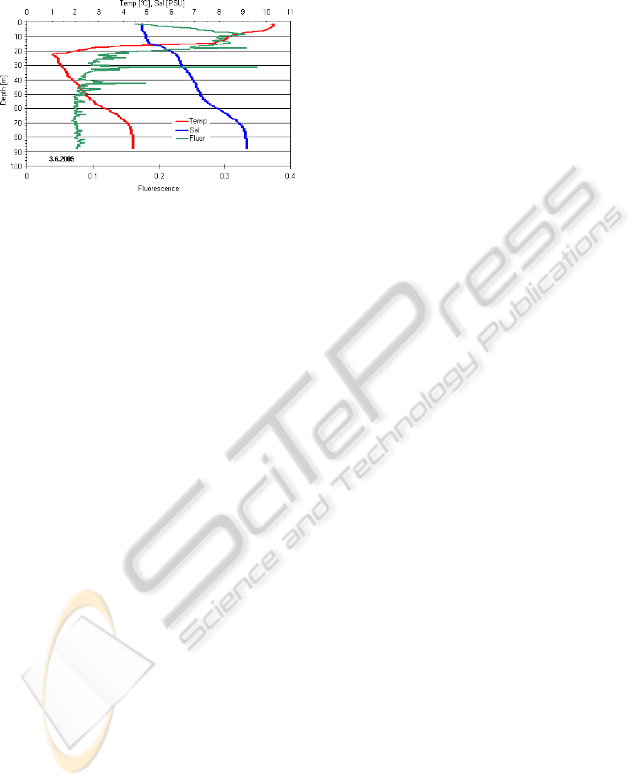
Figure 6: Complex vertical structure of temperature, salin-
ity and fluorescence against depth in the Baltic Sea.
4.2 Acoustic Communication
The range and reliability of underwater acoustic com-
munication is affected by a number of factors, in-
cluding signal attenuation, noise, reverberation and
sound channeling. A transmitted signal will be re-
flected from the surface or seabed and interfere with
the direct path signal. Variations in the temperature
and salinity at different depths will result in vari-
ations in the speed of sound, which will influence
the path of the signal. The sound speed profile for
the Baltic Sea is in fact conducive to the formation
of a sound channel, a depth at which acoustic sig-
nals will reflect internally due to a minimum in the
speed of sound. This channel is present mostly dur-
ing the summer, and varies in depth from 20m to 80m.
Using this sound channel, floats in the Baltic Sea
can theoretically achieve communications and rang-
ing over distances of up to 10km. In addition to com-
munication, acoustic transmissions may also be used
for ranging, by tracking the time of flight of mes-
sages. The SWARM floats implement a ping-pong
type scheme for measuring the round-trip travel time
between floats.
In this paper we use a simple linear model of the
probability of construction a communication between
drifters. When two floats are at immediate vicinity
they have a near guaranteed communication probabil-
ity, whereas at around 6 kilometers distance, the prob-
ability of having a communication channel between
two floats falls almost to zero. To determine the posi-
tion of onefloat from another, a ranging signal is used.
In effect, the float transmits a message and waits for
the reply from the receiving float.
A unit that has been on the surface sends its newly
obtained GPS position information through acoustic
modem once it has reached the defined communica-
tion depth and it is its time to communicate. Knowing
their own estimated positions and past trajectories, the
underwater units can reduce the uncertainty of their
position based on this information. A positional accu-
racy in the scale of hundreds of meters is acceptable
in this application. The biggest advantage of this po-
sitioning system is the fact, that there is no need for
any additional positioning devices, e.g. fixed acous-
tic buoys used in (Akyildiz et al., 2006; Dario et al.,
2005).
4.3 Algorithms and Implementations
The Kalman filter is an efficient and robust recursive
filter that estimates the internal state of a dynamic sys-
tem from a series of noisy measurements. It can also
estimate the variables which can’t be directly mea-
sured (Welch and Bishop, 1995). In our case, this
corresponds to the underwater sea current.
For this paper, the underwater localization estima-
tion is based on an Extended Kalman Filter(EKF).
The state variables are geographical positions of the
units and the vectors describing the currents in the
sea in different depth layers, while GPS fixes and dis-
tances between the floats through an acoustic ranging
being the measurements. Note that in this particu-
lar case, we do not include the depth coordinate into
the estimation as well as the vertical part of the sea
current vector because the measurement of the depth
itself is accurate enough. Since we can have a rela-
tively good measurement of the depth from the CTD
sensor, and taking the system propulsion into account
is not beneficial. This arrangement will also reduce
the complexity of the computation which is a limiting
factor in the real system onboard.
First we start with defining the state and measure-
ment vectors. The current vector at level j at position
(x,y) at k time step of EKF:
F
j
(x,y)(k) = [ f
jx
(k) f
jy
(k)]
T
(1)
In Section 4.1 we have described the basic situa-
tion for the Baltic Sea current and its unique charac-
ter of being layered. Thus, the environment can be
thought as series of layers that each have a flow vec-
tor representing the sea currents, which slowly varies
from one location to another. The units are located at
these layers as shown in Figure 7.
To better estimate such phenomena, we divided
the sea current vectors into three layers. In addition to
limit the computation complexity, we also choose this
number to correspond to the diving profile as shown
in Figure 2. The flow vector at position (x,y) at k time
step of EKF is defined as:
F
C
(x,y)(k) = [F
1
(x,y)(k) F
2
(x,y)(k) F
3
(x,y)(k)]
T
(2)
LOCALIZATION IN AN AUTONOMOUS UNDERWATER MULTI-ROBOT SYSTEM DESIGNED FOR COASTAL
AREA MONITORING
235
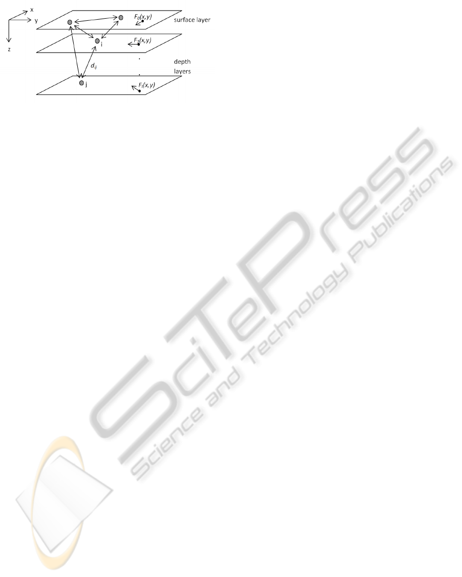
Figure 7: The units are located at layers that have different
flow vectors.
Position of a float at position(x,y) at k time step of
EKF:
P
j
(x,y)(k) = [x
j
(k) y
j
(k)]
T
(3)
In this project, we set EKF update rate to ∆t =
5minutes. Considering the real data collected by
Finnish Marine Research Institute, we can assume the
current vector is changing slowly both with respect to
horizontal location and time. The current dynamics is
modeled as:
F
C
(k) = F
C
(k− 1) + v(k) (4)
where v(k) is the system error of the current.
Let’s define the extended state Vector of EKF at
time step k:
˜
X(k) = [P
1
(k) P
2
(k) ... P
n
(k) F
C
(k)]
T
(5)
The corresponding extended state equation:
˜
X(k) = A(k)
˜
X(k− 1)
=
I ∆T
0 I
P(k− 1)
F
C
(k)
(6)
Here, system matrix A is updated each time ac-
cording to the depth layers (DL) of respective floats.
In other words, the prior prediction of the float loca-
tion is updated only by the current vector in its present
layer.
The example ∆T Matrix for 3 floats, while float 1
in depth 3, float 2 in depth 1, float 3 in depth 2:
∆T =
0 0 ∆t
∆ t 0
0 ∆t 0
(7)
All the floats maintain a depth list of all the known
floats. Since the measurements that these floats get
are different, even having the same equations running
internally, they have different estimations of the state
vector. Since the floats spends most of its time in the
waiting layer, when there is no depth update from the
others, they are assumed to be in the waiting layer
(check Figure 7).
Measurement equation:
Z(k) = [P
GPS1
(k) P
GPS2
(k) ... P
GPSn
(k)
d
12
(k) d
13
(k) ... d
(n−1)n
(k)]
T
(8)
Expected measurement:
h(
˜
X(k − 1)) = [P
1
(k) P
2
(k) ... P
n
(k)
kP
1
(k) − P
2
(k)k kP
1
(k) − P
3
(k)k
... kP
n
(k) − P
n−1
(k)k ]
T
(9)
To linearize h with respect to X for each update
step:
H(k) = ∂h(
˜
X
(k− 1))/∂
˜
X
(k− 1)
(10)
The overall running EKF for k time step:
˜
X(k) =
˜
X
−
(k) + K
k
(Z(k) − h(
˜
X
−
(k))) (11)
where the Kalman gain k is calculated in a stan-
dard EKF formula.
Note that in reality, it is rarely the case that the
float will get all the distances from all the other floats
and the distances between them. And it is only occa-
sionally when the float has a GPS fix on the surface
and gets GPS information from the others. In such
case the EKF automatically assumes those measure-
ments are missing and therefore not take them into
account while updating the state variables.
5 TESTS AND RESULTS
The simulated environment contains the flow vectors
and other environmental data that affect the positions
of the floats. The actual positions of the units are
maintained by the simulator, but they may be mea-
sured by the floats only in a way that is similar to the
real world, i.e. only the units that are on the surface
know their positions, and distances between floats are
only measured in seconds of sound travel time. The
user can control whether the units know only the dis-
tances from the unit itself to other units, or if they
know all the distances between all pairs of units. Ev-
ery unit contains a Kalman Filter that estimates the
positions of the units. The estimation is based on
the model that utilizes both the measured distances
between the units and the measured positions of the
units while on the surface. The real and the estimated
positions can be visually tracked and compared in real
time. The following figures are the comparison result
for a random chosen float in the system during their
respective missions.
ICINCO 2010 - 7th International Conference on Informatics in Control, Automation and Robotics
236
5.1 Turning vs. Line Traveling
In an area where the current vectors change quickly,
a float will typically make sharp turns. In such cir-
cumstances, its position estimates can be quite inac-
curate. On the other hand, in a case where the currents
are more homogenous, the float will follow a approx-
imately straight line and its estimation is obviously
better as time passes.
5.2 Test Configuration
The simulation test area is selected to be a bay area
not far from the Finnish coast. The key parameters
are set as shown in Table 1.
Table 1: Key parameters setting for Simulation.
Acoustic comm. interval once/hour
Surfacing interval 4 times/day
Surfacing time 10 minutes/dive
Comm. level waiting time 5 hours/dive
Meas. depth waiting time 40 minutes/dive
Kalman filter update interval once/5 minutes
These parameters are consist with the future real
test parameters.
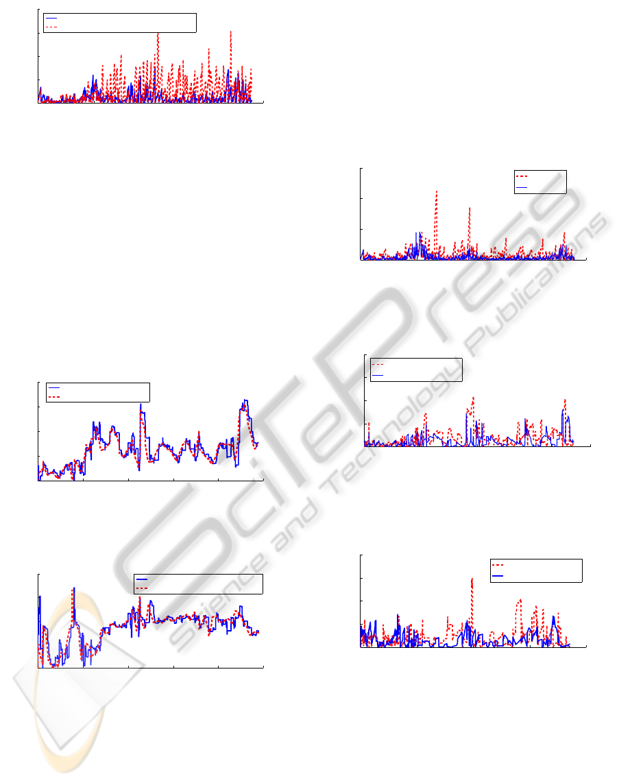
5.3 Baseline Estimation
As a baseline for estimating the quality of the local-
ization method, we use an alternative position esti-
mate which makes no use of acoustic ranging or com-
munication, and instead assumes the current position
to match the latest GPS position fix. See Figure 8 for
demonstration.
0 500 1000 1500 2000 2500 3000 3500 4000
0
1000
2000
3000
4000
Time (5mins)
Estimation Error (m)
5 Floats Scenario
Baseline Estimate
Figure 8: Estimation error for 5 floats randomly deployed
within 50m radius area with the the same diving profile.
Error is in Euclidian distance between the estimated and real
position.
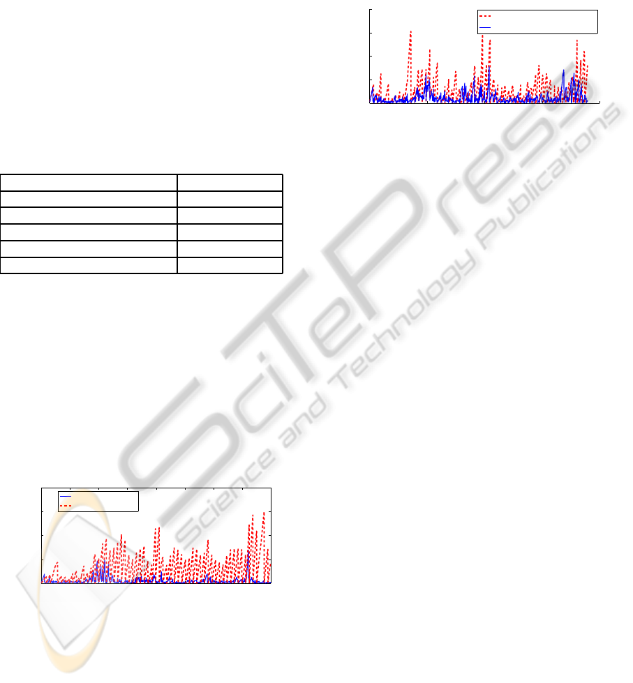
5.4 Data Information Exchange
High bandwidth acoustic data exchange between
floats in the Baltic Sea is extremely difficult. It is es-
pecially true when the floats are not always staying in
the communication layer, which does not even exist
in some cases. In Figure 9, we show the results from
both only acoustic communication enabled scenario
and acoustic & data exchange enabled case. Both of
them follow the communication probabilitymodel ex-
plained in Section 4.1.
0 1000 2000 3000 4000
0
500
1000
1500
2000
Time (5 Min)
Estimation Error (m)
Pingpong Only
Data Exchange Enabled
Figure 9: Estimation error comparison between acoustic
ranging only and data exchange scenario. (5 units that de-
ployed in a 50m radius area with same diving profile).
5.5 Deployment Strategy
To deployment pattern of the float is an important fac-
tor that has a considerable effect on the outcome of
the whole mission. When the drifters are deployed
within a small perimeter (radius 50m), for example
from an anchored boat, the high probability of ex-
changing information will increase the possibility to
have accurate position estimates. It is especially im-
portant for the drifters at their initialization phase.
Since they will experience almost the same current
vectors throughout their journey, which makes them
most likely remain close to each other throughout the
mission. The downside is of course the fact that the
system can only obtain data from a small proportion
of the area.
When deployed in a large area (radius 2km), the
floats disperse nicely during the mission. However,
the probability for the floats to get extra informa-
tion(information besides its own GPS fix when sur-
facing) is very low. It is so low that their estimation of
respective location is of a similar level of the bench-
mark estimation which only rely on GPS fixes.
To comprise, one possible solution is to deploy
floats into the water in a relatively small perime-
ter, and make their waiting depths slightly different.
Since the current field in the Baltic sea is clearly lay-
ered, the current vectors they experience is different.
By the end of the mission the floats drift nicely away
from each others (up to 6km). Of course, one down-
side for this approach is that, in reality, the communi-
cation channel is correlated to a specific depth level,
which will lower the probability of data exchange.
See Figure 10.
LOCALIZATION IN AN AUTONOMOUS UNDERWATER MULTI-ROBOT SYSTEM DESIGNED FOR COASTAL
AREA MONITORING
237
0 500 1000 1500 2000 2500 3000 3500 4000
0
500
1000
1500
2000
Time (5 Min)
Estimation Error (m)
Same Diving Profile
1 Meter Depth Difference Diving Profile
Figure 10: Estimation error comparison between 0m wait-
ing depth (same profile) difference against 1m depth differ-
ence deployment for 5 floats.
5.6 Current Estimation
One of the main target of the mission is to accurately
measure the subsurface currents speed and directions.
Usually this is of particular difficulty since the com-
plex situation underwater is hard to be measured di-
rectly. With the help of acoustic inter-robot commu-
nication, we have achieved some promising results.
Figure 11 and 12 show the current magnitude and
angle estimation generated by Kalman filter from the
one randomly chosen float.
0 500 1000 1500 2000 2500
0
0.05
0.1
0.15
0.2
Update Number (5 Min)
Current Speed (m/s)
Estimated Current Speed
Real Current Speed
Figure 11: Current estimation magnitude error for 5 floats
randomly deployed within 50m radius with the same diving
profile.
0 500 1000 1500 2000 2500
0
50
100
150
200
Update Number (5 Min)
Current Angle (degrees)
Estimated Current Angle to East
Real Current Speed to East
Figure 12: Current estimation angular error for 5 floats ran-
domly deployed within 50m radius with the same diving
profile.
There is a small lagging of the filter result towards
the real environmental current data, which can be ex-
plained by the filter properties. However, the pre-
liminary results are promising and deserve further re-
search.
5.7 Float Numbers
Obviously, one of the most important factor is the
number of floats in a given mission. During a mission,
with a greater number of floats, there are more GPS
fixes and distance measurements to share and there is
a higher probability to gather such information from
the communication between the floats. See Figures
from 13, 14, 15.
0 1000 2000 3000 4000
0
1000
2000
3000
Time (5 Min)
Estimation Error (m)
3 floats
15 floats
Figure 13: Estimation error comparison between 3 units and
15 units mission. Deployed in 50m radius area with 1 meter
depth difference in communication level.
0 500 1000 1500 2000
0
0.05
0.1
0.15
0.2
Update Number (5 Min)
Current Speed
Estimation Error (m/s)
3 floats scenario
15 floats scenario
Figure 14: Comparison of absolute current speed estimation
error between 3 floats and 15 floats scenarios. Both scenar-
ios deploy within 50 meter radius and 1 meter waiting depth
difference.
0 500 1000 1500 2000
0
50
100
150
200
Update Number (5 Min)
Estimation Error (degree)
3 floats scenario
15 floats scenario
Figure 15: Comparison of absolute current direction esti-
mation error between 3 floats and 15 floats scenarios. Both
scenarios deploy within 50 meter radius and 1 meter waiting
depth difference.
The number of floats in a given mission gives an
interesting topic to research. The performance im-
provement also added a degree of difficulty and com-
plexity for acoustic communication, data exchange
via acoustic modem and the localization algorithm.
ICINCO 2010 - 7th International Conference on Informatics in Control, Automation and Robotics
238

6 CONCLUSIONS AND FUTURE
WORK
Multi-robot systems have a great inherent potential in
various applications requiring localization and navi-
gation capabilities. In this paper, we have shortly
introduced a multi-robot system suitable for opera-
tions in the shallow water conditions near the coast-
line. The main contribution of this paper is the valida-
tion of our implementation of a localization algorithm
in these demanding conditions. The obtained results,
which are drawn from extensive simulations based
on real case scenarios and environmental data, have
proved the validity and effectiveness of our approach
for the localization of these intelligent autonomous
profiling floats.
However, there is much more yet to be explored in
terms of our research. We will briefly introduce a bet-
ter underwater communication channel modeling, in
particular for the layered Baltic sea case. Further tests
scenarios with different surfacing intervals, acoustic
communication intervals and dynamic mission plan-
ning will be conducted. Later research will also
include optimization between communication band-
width, energy and reliability, data compression in data
communication and other filtering algorithms. Real
world robotic tests with renewed four unit system will
be started in summer 2010 and they will further guide
the future research.
ACKNOWLEDGEMENTS
We would like to thank the Academy of Finland for
funding the Finnish Center of Excellence in Generic
Intelligent Machines (GIM), the SWARM consor-
tium, Jorma Selk¨ainaho, Janne Paanaj¨arvi , Sami
Terho from GIM, and Antti Westerlund (Finnish Me-
teorological Institute).
REFERENCES
Akyildiz, I. F., Pompili, D., and Melodia, T. (2006). State-
of-the-art in protocol research for underwater acoustic
sensor networks. In WUWNet ’06: Proceedings of
the 1st ACM international workshop on Underwater
networks, pages 7–16, New York, NY, USA. ACM.
Costanza, R., d’Arge, R., de Groot, R., Farber, S., Grasso,
M., Hannon, B., Limburg, K., Naeem, S., O’Neill,
R. V., and Paruelo, J. (1998). The value of the world’s
ecosystem services and natural capital. Ecological
Economics, 25(1):3–15.
Dario, I. A., Akyildiz, I. F., Pompili, D., and Melodia, T.
(2005). Underwater acoustic sensor networks: Re-
search challenges. Ad Hoc Networks (Elsevier, 3:257–
279.
Davis, R. E., Sherman, J. T., and Dufour, J. (2001). Profil-
ing ALACEs and other advances in autonomous sub-
surface floats. J. Atm. Ocean. Tech., 18(6):982–993.
McFarland, D. and Honary, E. (2003). Flock distortion: A
new approach in mapping environmental variables in
deep water. Robotica, 21(4):365–383.
Saarinen, J., Maula, A., Nissinen, R., Kukkonen, H.,
Suomela, J., and Halme, A. (2007). Gimnet - infras-
tructure for distributed control of generic intelligent
machines. In Proceedings of the 13th IASTED In-
ternational Conference on Robotics and Applications
Telematics 2007. The 13th IASTED International
Conference on Robotics and Applications Telematics.
Vainio, M., Halme, A., Troshin, I., Stipa, T., Seppala, J.,
Pollehne, F., Bauerfeind, E., Haardt, H., Brault, P.,
Seube, N., Smerdon, A., Caine, S., Swale, B., and
Hakala, A. (2004). Autonomous underwater multi-
probe system for coastal area/shallow water monitor-
ing (swarm). In Proceedings of the EurOCEAN 2004
Conference, Ireland. EurOCEAN 2004 Conference,
Galway 2004.
Welch, G. and Bishop, G. (1995). An introduction to the
kalman filter.
LOCALIZATION IN AN AUTONOMOUS UNDERWATER MULTI-ROBOT SYSTEM DESIGNED FOR COASTAL
AREA MONITORING
239
