
DECENTRALISED ACTIVE CONTROLLER
Chiheb Ameur Abid and Belhassen Zouari
LIP2 Laboratory, University of Tunis, El Manar 2, Tunis, Tunisia
Keywords:
Supervisory control theory, Coloured Petri nets, Discrete event systems, Distributed systems.
Abstract:
This paper deals with the synthesis problem of controllers based on Coloured Petri nets in a decentralized set-
ting. An approach is proposed to derive a decentralized controller consisting of a set of local controllers. Each
local controller, modeled by a CP-net, observes and controls a portion of the plant model. Communication
between local controllers is performed only when it is necessary allowing the appropriate local controller to
restrict the behavior of its observed portion in order to meet the control specification.
1 INTRODUCTION
The supervisory control theory for discrete-event sys-
tems (DES) aims to control a plant model by the au-
tomatic synthesis of a controller (Ramadge and Won-
ham, 1989). Due to their easily understood graphi-
cal representation and well-formed mathematical for-
malism, Petri nets have been widely used to investi-
gate this theory (Giua and DiCesare, 1994; Holloway
et al., 1997; Ghaffari et al., 2003).
In practice, implementing a centralised controller
is not always feasible since a plant model can be a
collection of several semi-autonomous components
geographically dispersed. As a solution, the decen-
tralised control (Rudie and Wonham, 1992) allows
to looks for a fixed number of controllers such that
each controller observes and controls a portion of the
plant. The decentralised control can be performed
with communication (Guan and Holloway, 1995),
without communication (Basile et al., 2007), or by in-
troducing a central coordinator (Chen and Baosheng,
1991).
Although, they seem to be powerful enough to de-
scribe complex systems in a manageable way, and
their expressivenesscapabilities, few works have used
Coloured Petri nets (CP-nets) (Jensen et al., 2007) to
investigate the control problem. In (Makungu et al.,
1999), the problem of forbidden states is tackled for
controlled CP-nets. In our previous works (Abid and
Zouari, 2008; Abid et al., 2010), we have proposed a
first approach combining both theory of regions and
CP-nets in which the obtained controller is reduced
to one place. Also, we have optimised the same ap-
proach for symmetric systems to tackle the state ex-
plosion problem. In a second approach, we generate
a CP-net controller as an active process without using
the theory of regions.
The work presented in this paper addresses the
supervisory control problem in a decentralised set-
ting. The considered plant model consists of sev-
eral modules, modelled by CP-nets, which communi-
cate through the synchronisation of common actions.
Based on global control specifications expressed in
terms of forbidden states, we propose to build a de-
centralised active controller. Such a controller con-
sists of a set of communicating local controllers as-
sociated with modules. The role of a each local con-
troller is to observe and to control its associated mod-
ule.
The remainder of the paper is organised as fol-
lows. Section 2 introduces the CP-net models. Sec-
tion 3 provides the computation of necessary infor-
mation related to the building of a decentralised ac-
tive controller. Section 4 deals with the building of a
CP-net model representing a local controller. Finally,
section 5 summarizes the main conclusions and per-
spectives of this work.
2 PRELIMINARIES
In this paper, the plant model to be considered is as-
sumed to be made up of several communicating mod-
ules. The communication is ensured via the execu-
tion of common actions. Further, we assume that each
module corresponds to a Resource Allocation System
(RAS). A RAS, as defined in (Reveliotis et al., 1997),
corresponds to a set of resources, that can be of many
252
Ameur Abid C. and Zouari B. (2010).
DECENTRALISED ACTIVE CONTROLLER.
In Proceedings of the 7th International Conference on Informatics in Control, Automation and Robotics, pages 252-259
DOI: 10.5220/0002946102520259
Copyright
c
SciTePress

types and available in any amount of copies, and a
set of generic processes, that can be instantiated in a
collection of processes.
Formally, a RAS is a tuple (R, GP, GetR, PutR)
where:
• R = (RT,Rnb) is the resource specification, s.t.RT
is the finite set of resource types, and Rnb ∈
Bag(RT)
1
is a multiset on RT representing the
amount of available copies of each resource type.
• GP is the finite set of generic processes.
A generic process Gi =< P
si
, F
i
,C
i
> is defined by
a finite state machine (FSM) as follows:
– P
si
= {p
0i
, p
i1
, p
i2
, ..., p
il(s)
} is the finite set of
states, where p
0i
represents the ’idle’ place of
the generic process. The ’idle’ place is the ini-
tial place of whole process instance.
– F
i
: P
si
→ P
si
is the flow relation representing
the state transitions.
– C
i
is the finite set of identities of process in-
stances.
• GetR : F
i
→ Bag(R) is the resource allocation
function
• PutR : F
i
→ Bag(R) is the resource restitution
function
A RAS can be modelled by a CP-net. Such a CP-
net is built from a collection of FSMs (representing
the generic processes), a resources place, and connec-
tion arcs related to the resource management.
A marked CP-net N representing a RAS, where
N =< P, T,C,W
−
.W
+
, Φ, M
0
>, is defined as follow-
ing:
• P = P
S
∪ {p
R
} is a finite set of places where P
S
=
S
|GP|
i=1
P
si
, and p
R
represents the resources place
such that P
si
∩ P
sj
=
/
0 and P
S
∩ {p
R
} =
/
0.
• T is a set of transitions recursively built as fol-
lows:
Initially T =
/
0, then T = T ∪ { f
ij
};i =
1, .., |GP|; j = 1, .., |F
i
|.
The elements of T may be lexicographically re-
named so as we can use the notation T = {t
i
};i =
1, .., |T|.
• C =
S
|GP|
i=1
C
i
S
|GP|
i=1
(C
i
× C
r
) ∪ C
r
where C
r
is a
colour domain of p
R
,C
r
= RT.
• W
−
= W
−
S
∪ W
−
R
, where W
−
S
: (P
s
× T) →
{0,
S
|GP|
i=1
X
i
} such that X
i
is a variable defined on
C
i
, and W
−
R
: ({p
R
} × T) → Bag(C
r
) such that
∀t ∈ T,W
−
R
(p
R
,t) = GetR( f
ij
).
• W
+
= W
+
S
∪ W
+
R
, where W
+
S
: (P
s
× T) →
{0,
S
|GP|
i=1
X
i
} such that X
i
is a variable defined on
C
i
, and W
+
R
: ({p
R
} × T) → Bag(C
r
) such that
∀t ∈ T,W
+
R
(p
R
,t) = PutR( f
ij
).
• M
0
the initial marking is a function defined on P,
such that M
0
(p) = Bag(C(p)), for all p ∈ P. M
0
is defined as follows:
∀p ∈ P
S
\(
S
|GP|
i=1
{p
0i
});M
0
(p) = 0;M
0
(p
R
) = Rnb
and M
0
(p
0i
) ≥ 1.
• Φ is a function which associated a guard with any
transition. By default Φ(t) is true for any transi-
tion t.
We consider a decentralised system consisting of
several modules that communicate. We assume that
each module corresponds to a RAS modelled by a
CP-net. The communication between CP-nets can
be performed through two possible forms. The asyn-
chronous form by means of shared places, or in syn-
chronous form by means of shared transitions. Since
communication via shared places can be transformed
into synchronisation via shared transitions, it suf-
fices to support the latter (Christensen and Petrucci,
2000). Modular CP-nets (Christensen and Petrucci,
1995) allow to model efficiently such systems. The
latter models introduce structure to CP-nets by let-
ting modules specified separately. For further details
about modular CP-nets, one may refer to original pa-
pers (Christensen and Petrucci, 1995).
Let be K = {1, ..., m}. A modular CP-net is a pair
MCPN = ({N
k
|k ∈ K}, TF) satisfying:
• {N
k
|k ∈ K} is a set of modules such that ∀k ∈
K, N
k
=< P
k
, T
k
,C
k
,W
−
k
.W
+
k
, Φ
k
> is a CP-net,
• TF ⊆ 2
T
is a finite set of transition fusion sets
where T =
S
k∈K
T
k
.
In a modular CP-net, all transitions belonging to
the same transition fusion set are fired as one indivis-
ible action sharing the values assigned by a common
binding. The binding is a function used to assign only
one value for a variable of a transition fusion set, i.e.
a variable name refers to the same value for all transi-
tions in a transition fusion set.
Example 1. Throughout this paper, we consider the
producer-consumer problem. In this problem, there
are two kinds of processes, namely producers and
consumers, sharing a stock (a resource). Figure 1(a)
gives a CP-net modelling this problem. C
1
= {pr},
C
r
= { f, o} and C
2
= {co} are the colour classes
of this net. A token pr is used to model the be-
haviour of a producer, while a token co allows to
model the behaviour of a consumer. The token f indi-
cates the number of free places in the stock, while the
token o indicates the produced objects. We assume
that the stock capacity is two. The colour domains
of places are: C(a1) = C(a2) = C
1
, C(r) = C
r
and
DECENTRALISED ACTIVE CONTROLLER
253

(a)
(b)
b2
X
X
a1
a2
X
b1
ta
tprod
tcons
r
tb
tcons
X
X
X
Module A
Module B
X
f
f
X
2pr
C1
C3
2co
2f
b2
X
X
a1
a2
X
b1
ta
tprod
tb
tcons
o
o
X
X
X
X
r
X
f
f
2pr 2co
2f
o
o
Figure 1: Example of CP-nets.
C(b1) = c(b2) = C
2
.
As it is illustrated in Figure 1, the latter CP-net can be
decomposed into two modules A and B. These mod-
ules are both synchronised on transition tcons. The
two shared transitions tcons of module A and B con-
stitute a transition fusion set.
3 DECENTRALISED ACTIVE
CONTROLLER MODEL
In this section, we present the synthesis approach of
a decentralised active controller. As a plant model,
we consider a decentralised DES consisting of sev-
eral modules modelled by a modular CP-net. We
assume that every module is structured on a set of
generic processes sharing a set of resources. As our
aim is to resolve the state forbidden problem, the con-
trol specification is then expressed in terms of forbid-
den markings. In a first step, we use the reachability
graph to determine the dangerous markings as well
as transitions to be disabled from firing by the local
controllers, called the forbidden transitions. The dan-
gerous markings are markings from which the control
actions must be applied by disabling some forbidden
transitions.
3.1 Architecture of a Decentralised
Active Controller
A decentralised controller consists of a set of local
controllers where each one is associated with one
module of the plant model. The preventing of a tran-
sition from firing in a dangerous marking is ensured
by the local controller associated with the module to
which the transition belongs. Each local controller
has to observe permanently the evolution of its asso-
ciated module by tracking its current local marking.
However, since a control action depends mainly on
the reached global state of the plant model (the en-
tire system), then a local controller requires to observe
some evolutions of the plant model. Such a global ob-
servation is performed, when it is necessary, by com-
municating with the other local controllers. In sum-
mary, each derived local controller associated with a
module has three main features:
• Observing the current local state of its module,
• Communicating with the other local controllers to
determine the global state of the plant model when
it is necessary,
• Performing control actions by preventing the fir-
ing of some transitions of its associated module.
For sake of simplicity, we propose to decompose
a local controller into two submodules. The first one,
called communication submodule, observes and dif-
fuses the current local marking of its associated mod-
ule, while the second submodule, called executor sub-
module, performs the control actions by preventing
some transitions of its associated module from fir-
ing. For this purpose, the executorsubmodule must be
able to identify when the overall plant model reaches
a dangerous marking. This ability is ensured by com-
municating with communication submodules. It is
worth noting that an executor submodule is associated
with a module only when there exists at least one tran-
sition of the module to be disabled by the controller.
3.2 Determining the Admissible
Behaviour
The supervisory control theory classifies the transi-
tions into two categories. First category consists of
the controllable transitions which may be disabled
when it is necessary. In contrast, the transitions be-
longing to the second category, called uncontrollable
transitions, are beyond any control procedure. Hence,
we assume that the transition set of the plant model is
partitioned into two disjoint subsets: the set of con-
trollable transitions and the set of uncontrollable ones.
The disabling of a transition is performedin a dan-
gerous marking from which the firing of the transition
leads to a forbidden marking. So that, we have to
identify the set Ω of state-transitions to be disabled.
Every element of Ω is a couple (M, (t, c)) where M
is a dangerous marking, and (t, c) is a controllable
coloured transition, called forbidden transition, such
that the firing of t with colour c from M yields to a
forbidden marking.
The set Ω of state-transitions is computed from
the reachability graph of the plant model. The ba-
sic idea is to remove forbidden nodes. Nodes becom-
ing unreachable from the initial marking and the non
coreachable markings must be removed from the ad-
missibility graph. The identification of dangerous and
ICINCO 2010 - 7th International Conference on Informatics in Control, Automation and Robotics
254
forbidden nodes is performed according to the follow-
ing rules:
• a marking is qualified as dangerous if it has at
least one output arc where its destination is a for-
bidden marking,
• a marking is qualified as forbidden when it has no
output arcs and it is not a final marking, or it is a
dangerous marking and it has at least one output
arc labelled by an uncontrollable transition,
• every forbidden marking must be removed with
its input and output arcs.
In (Abid et al., 2010), an algorithm is proposed for
the computation of the admissibility graph and the set
Ω of state-transitions.
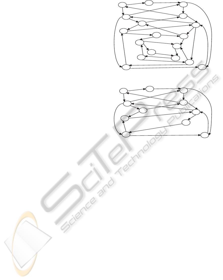
Example 2. Consider the example of producer-
consumer. Its reachability graph is illustrated by
Fig. 2. Assume that we want to restrict the stock ca-
pacity to hold only one object. Therefore, the initially
specified set of forbidden markings is
FM = {M10, M13, M14, M15, M16, M17}.
By determining the admissible behaviour, we ob-
tain the admissibility graph of Fig. 3 and the
set of state-transitions Ω = {(M6, (tprod, < pr, o >
)), (M11, (tprod, < pr, o >)), (M12, (tprod, < pr, o >
))}, where M6 =< 1, 1, 1, 1, 1, 0 >, M11 =<
1, 1, 1, 1, 0, 1 > and M12 =< 0, 2, 1, 1, 0, 1 >. Thus,
the coloured transition (tprod, < pr, o >) has to be
disabled in markings M6, M11 or M12.
Let d be a dangerous state. We use FT(d) to de-
note the set of coloured forbidden transitions related
to d. Each element of FT(d) is a coloured transition
(t, c) such that the firing of (t, c) in d leads to a forbid-
den or inadmissible state. Let k be a module, we use
FT
k
to to determine the set of forbidden transitions of
module k. Let DS be the set of dangerous states. FT
may be viewed as an application defined as follows:
FT : DS → 2
T
d 7→ { (t, c)|(d, (t, c)) ∈ Ω}
Basically, a local controller can only observe the
behaviour of its associated module. Since each lo-
cal controller has to communicate with the other local
controllers in order to build and identify dangerous
markings, we introduce the notion of dangerous local
marking. A dangerous local marking of a module is a
local marking from which we can build a dangerous
marking.
Let M
k
be a local marking of module k.
M
k
is a local dangerous marking if f ∃M
′
∈ [M
0
i :
M
′
k
= M
k
∧ M
′
is a dangerous marking.
For every local marking associated with a module
k, we make available the following data:
M0
M2
M5
M1
M4
M8
M11
M14
M7
M10
M9
M12
M13
M6
M3
M15
M16
M17
ta,<pr>
tb,<co>
ta,<pr>
tb,<co>
tprod,<pr,o>
tcons,<co,o>
ta,<pr>
tcons,<co,o>
tprod,<pr,o>
tprod,<pr,o>
tb,<co>
ta,<pr>
ta,<pr>
ta,<pr>
tprod,<pr,o>
ta,<pr>
tprod,<pr,o>
ta,<pr>
tb,<co>
tb,<co>
ta,<pr>
tcons,<co,o>
tprod,<pr,o>
ta,<pr>
tb,<co>
tprod,<pr,o>
tb,<co>
tcons,<co,o>
tb,<co>
ta,<pr>
tb,<co>
tcons,<co,o>
ta,<pr>
Figure 2: Example of a reachability graph.
M0
M2
M5
M1
M4
M8
M11
M7
M12
M6
M3
ta,<pr>
tb,<co>
ta,<pr>
tb,<co>
tprod,<pr,o>
tcons,<co,o>
ta,<pr>
tcons,<co,o>
tprod,<pr,o>
tprod,<pr,o>
tb,<co>
ta,<pr>
ta,<pr>
ta,<pr>
ta,<pr>
tcons,<co,o>
tb,<co>
tb,<co>
ta,<pr>
Figure 3: Example of admissibility graph.
• the set of dangerous markings,
• the set of dangerous local markings of module k,
• the set FT
k
of forbidden transitions of module k
and their correspondent dangerous marking.
Example 3. From the set Ω computed in previous ex-
ample, we determine the following sets:
The set of dangerous local markings of module A is
SDLM
A
= {< 1, 1, 1, 1 >, < 0, 2, 1, 1 >}.
In module A, there exists only one forbidden transi-
tion:
FT
A
(M6) = FT
A
(M11) = FT
A
(M12) = {(tprod, <
pr, o >)}.
The set of dangerous local markings of module B is
SDLM
B
= {< 1, 0 >, < 0, 1 >} .
In module B, there is no forbidden transitions, then:
FT
B
(M6) = FT
B
(M11) = FT
B
(M12) =
/
0.
4 A LOCAL CONTROLLER
MODEL
Now, we describe the CP-net model of a local con-
troller. The key idea of the decentralised active con-
troller approach is that a local controller must be able
to detect the reaching of a dangerous state. Once a
DECENTRALISED ACTIVE CONTROLLER
255

Figure 4: CP-net modelling a local controller.
dangerous marking is detected, the local controller re-
moves appropriate authorisations in order to disable
the firing of some forbidden transitions of its associ-
ated module. Basically, a local controller has to han-
dle, permanently, information about the current local
marking of its module. In contrast, a global marking
is determined for a local controller through commu-
nication. Intuitively, a local controller diffuses its ob-
served local state to the other local controllers when it
detects that the observed local state may be a part of
a dangerous global state.
As precited, a local controller can be seen as the
composition of two submodules, namely the com-
munication and the executor submodules. The main
purpose of the first submodule is to determine and
diffuse the current local marking of its associated
module to other local controllers, while the executor
submodule performs the control actions. More pre-
cisely, the communication submodules send the deter-
mined local markings to every executor submodule.
Then, each executor module can determine whether
the plant model reaches a dangerous global mark-
ing from which some transitions have to be prevented
from firing.
The communication submodule diffuses the cur-
rent local state of its associated module according to
the following rules:
• Its associated module reaches a dangerous local
state from another local state (dangerous or not),
• Its associated module reaches a non dangerous lo-
cal state from a dangerous local state.
Figure 4 describes the CP-net modelling a local
controller. Let us consider a DES, made up of m
modules, modelled by a modular CP-net MCPN =
({N
k
|k ∈ K = {1, ..., m}}, TF), where ∀k ∈ K, N
k
=<
P
k
, T
k
,C
k
,W
−
k
,W
+
k
, M
0,k
, Φ
k
>. In a first step, we de-
tail the formal definition of the communication sub-
module. Secondly, we define the executor CP-net
submodule.
Step 1: the communication submodule. Let us
consider the CP-net N
k
modelling module k ∈
K. The model representing module k connected
to its associated communication submodule is a
CP-net N1
k
obtained from N
k
, so that N1
k
=<
P1
k
, T1
k
,C1
k
,W1
−
k
,W1
+
k
, M1
0,k
, Φ1
k
>.
P1
k
= P
k
∪ {CLM
k
, DLM
k
, LaS
k
}, where:
• CLM
k
represents the current local marking of
module k,
• DLM
k
contains the set of of dangerous local mark-
ings associated with module k,
• LaS
k
indicates whether the last communicated
current local marking of module k is dangerous,
or not.
T1
k
= T
k
∪ {S − DLM
k
, S −CLM
k
}, where:
• S− DLM
k
is a synchronised transition allowing to
send a dangerous local marking,
• S−CLM
k
is a synchronised transition. It allows to
send a non dangerous current local marking when
it is reached from a dangerous global marking.
Now, we introduce the following additionnal colour
classes:
C
num
= {1, 2, . . . , MaxInt} is a colour class represent-
ing a set of finite positive integers. The elements of
C
num
are used to model the occurrences of some given
tokens. We assume that MaxInt is large enough to be
greater than the bound of maximum occurrences of
any token in a reachable marking,
C
status
= {tosend, sent} is a colour class where the ob-
ject sent (resp. tosend) is used to identify whether a
current local marking is already sent to all executor
submodules (resp. not yet sent),
C
flag
= {d flag, o flag} where the object d flag
(resp. o flag) is used to indicate whether the last
diffused local marking is dangerous (resp. not dan-
gerous).
Every added place is characterised by a colour domain
and an initial marking defined as follows:
• Place LaS
k
allows to hold information indicat-
ing whether the last communicated current local
marking is dangerous or not. For this purpose,we
use the colours of C
flag
. Thus, C(LaS
k
) = C
flag
.
Initially, place LaS
k
is empty.
• Place CLM
k
holds the current local marking of
module k, and information whether this local
marking is communicated. A local marking is
represented by a tuple made up of counters. Each
counter holds the information about the occur-
rence of tokens in a given place (according to the
lexical order) among process places and the re-
source place. Such a representation is obtained
ICINCO 2010 - 7th International Conference on Informatics in Control, Automation and Robotics
256

through a Cartesian product performed on the ba-
sis of the number l of process classes in module k,
the number of places x
i
per a process i and the re-
source class C
r,k
. More precisely, a local marking
is an element of the following colour class:
C
LM,k
=
l
O
i=1
x
i
O
j=1
C
num
|C
r,k
|
O
u=1
C
num
.
In addition to the current local marking, place
CLM
k
holds information indicating whether the
current local marking is already communicated
or not. It is performed by using elements of the
colour class C
status
. Thus, the domain class of
place CLM
k
is C(CLM
k
) = C
LM,k
×C
status
.
Place CLM
k
is always mono-marked and its ini-
tial marking M
0,k
(CLM
k
) is determined from the
initial marking of module k.
• Place DLM
k
holds the set of dangerous local
markings of module k. Each marking is repre-
sented in identical way as for place CLM
k
. So that
C(CLM
k
) = C
LM,k
. Initially, place DLM
k
holds
the set SetDLM
k
which represents the dangerous
local markings of module k, i.e. M
0,k
(DLM
k
) =
SetDLM
k
. This place is only read accessed.
Now, we give the colour functions associated with the
arcs connecting places to transitions.
• As place CLM
k
holds the current local marking
of module k modelled by CP-net N
k
, then it has to
be connected to every transition of T
k
in order to
keep its information up to date. This is because
the firing of every transition of T
k
may update the
current local marking of module k. Place CLM
k
is
connected to every transition of T
k
with an input
arc (reading marking) and output arc (updating
marking) as follows:
∀t ∈ T
k
,
W1
−
k
(CLM
k
,t) =< X
1,1
, . . . , X
i, j
,Y
1
, . . . ,Y
u
>=
< X >, where X
i, j
is a variable defined on C
num
computing the number of tokens in place i of the
process type j (p
ij
∈ P
k
), and Y
u
is a variable
defined on C
num
reading the occurrence of colour
u in resource places.
∀t ∈ T
k
,
W1
+
k
(CLM
k
,t) =< X
′
1,1
, . . . , X
′
i, j
,Y
′
1
, . . . ,Y
′
u
>=
< X >, where X
′
i, j
and Y
′
u
are variables defined on
C
num
and determined as follows:
X
′
i, j
= X
i, j
− χ, where χ = W
+
(p
ij
,t) −
W
−
(p
ij
,t),
Y
′
u
= Y
′
u
− ξ, where ξ is computed as follows:
W
−
k
(r,t) =
∑
i
α
i
.r
i
,
W
+
k
(r,t) =
∑
i
α
′
i
.r
i
⇒ ξ = α
′
u
− α
i
.
• The colour functions related to S− DLM
k
:
W1
+
k
(DLM
k
, S − DLM
k
) = W1
−
k
(DLM
k
, S −
DLM
k
) =< D
k
>;
W1
−
k
(CLM
k
, S − DLM
k
) =< D
k
,tosend >;
W1
+
k
(CLM
k
, S − DLM
k
) =< D
k
, sent >;
W1
−
k
(LaS
k
, S − DLM
k
) =< Y >;
W1
+
k
(LaS
k
, S − DLM
k
) =< d flag >;
where D
k
∈ C
LM,k
and Y ∈ C
flag
.
The colour functions related to S−CLM
k
:
W1
−
k
(CLM
k
, , S−CLM
k
) =< O
k
,tosend >;
W1
+
k
(CLM
k
, , S−CLM
k
) =< O
k
, sent >;
W1
−
k
(LaS
k
, S −CLM
k
) =< d flag >;
W1
+
k
(LaS
k
, S −CLM
k
) =< o flag >;
where [O
k
∈ C
LM,k
].
Transition S − CLM
k
is associated with the guard
[O
k
6∈ SetDLM
k
].
Step 2: the executor submodule. Now, we
present the features of the executor submod-
ule. It is obtained from the CP-net N1
k
=<
P1
k
, T1
k
,C1
k
,W1
−
k
,W1
+
k
, M1
0,k
, Φ1
k
>, modelling
module k with its associated communication submod-
ule.
The model representing a module k and its local con-
troller is a CP-net N
∗
k
obtained from N1
k
, so that
N
∗
k
=< P
∗
k
, T
∗
k
,C
∗
k
,W
∗−
k
,W
∗+
k
, M
∗
0,k
, Φ
∗
k
>, where:
P
∗
k
= P1
k
∪ {GM
k
, DM
k
, AS
k
, AT
k
}, where:
• GM
k
represents the global marking of the overall
plant model,
• DM
k
holds the set of dangerous global markings,
• AS
k
represents the alert state of the local controller
associated with module k,
• AT
k
contains the set of authorisations for forbid-
den transitions of module k.
T
∗
k
= T1
k
∪ { A − IN
k
, A − OUT
k
}
S
i∈K\{k}
{S −
DLM
k,i
}
S
i∈K\{k}
{S−CLM
k,i
}, where:
• A− IN
k
allows to enter the alert state,
• A− OUT
k
allows to quit the alert state,
•
S
i∈K\{k}
{S − DLM
k,i
} is a set of shared transi-
tions. The firing of a transition S − DLM
k,i
al-
lows the executor submodule k to receive a dif-
fused dangerous local marking from the commu-
nication submodule i.
•
S
i∈K\{k}
{S − CLM
k,i
} is a set of shared transi-
tions. The firing of a transition S−CLM
k,i
allows
module k to receive a non dangerous local mark-
ing from the communication submodule i.
The colour domain and the initial marking associated
with every added place are as follows:
DECENTRALISED ACTIVE CONTROLLER
257

• Place GM
k
holds the marking of the overall plant
model. Its colour domain is a Cartesian product
of colour classes representing local markings of
individual modules. Thus, the colour domain of
GM
k
is defined as follows:
C
∗
(GM
k
) =
∏
i∈K
C
LM,i
Initially, the marking of place GM
k
represents the
initial marking of the overall plant model.
• Place DM
k
maintains the set of state-transitions of
module k. Its colour domain is
C
∗
k
(DM
k
) = C
∗
(GM
k
) ×C
FT,k
, where C
FT,k
denotes the colour class represent-
ing forbidden transitions of module k. This place
is only read accessed.
• Place AS
k
indicates that the controlled module k
is in alert state. Its marking indicates the global
marking of the controlled system and the transi-
tion to be prevented from firing.
C
∗
k
(AS
k
) = C
∗
(GM
k
)
Initially, place AS
k
is empty as all forbidden tran-
sitions are authorised.
• Place AT
k
is connected to every forbidden transi-
tion by one input/ output arc in order to check the
presence of the associated firing authorisation:
∀t ∈ FT
k
,W
∗+
k
(AT
k
,t) = W
∗−
k
(AT
k
,t) =< Xt >,
where Xt is defined on C
FT,k
and represents the
identity of the coloured forbidden transition. Fur-
ther, we associate with every forbidden transition
the following guard expression:
[
_
c∈C(t)
[
^
X∈Var(t)\{Xt}
X = X(c) ∧ Xt = id ft(t, c)]]
where id ft is a function which maps a forbidden
coloured transition (t, c) to an element of C
FT,k
representing the identity of (t, c). This associated
guard expression allows to associate the appropri-
ate authorisation for a coloured transition.
The colour functions of the arcs connecting the con-
troller places to a subset of T
k
and to the transitions
A− In
k
and A− Out
k
are defined as follows:
W
−∗
k
(DM
k
, A − In
k
) = W
∗+
k
(DM
k
, A − In
k
) =<
D, FT − D >
W
−∗
k
(GM
k
, A − In
k
) = W
∗+
k
(GM
k
, A − In
k
) =< D >
W
−∗
k
(AT
k
, A − In
k
) =< FT − D >
W
+∗
k
(AS
k
, A − In
k
) =< D, FT − D >
W
+∗
k
(AS
k
, A − Out
k
) =< D, FT − D >
W
−∗
k
(GM
k
, A − Out
k
) =< C >
W
+∗
k
(AT
k
, A − Out
k
) =< FT − D > .
D and C ∈ C
GM
, FT − D ∈ C
FT,k
.
Transition A − Out
k
is associated with the predicate
[C 6= D]. For every i ∈ K, place GM
k
is connected
to the S − DLM
k,i
and S − CLM
k,i
allowing to update
the local marking of module i in place GM
k
. The
associated colour functions are defined as follows:
W
−∗
k
(GM
k
, S − DLM
k,i
) =< X
1
, ..., X
i
, ..., X
m
>;
W
+∗
k
(GM
k
, S−DLM
k,i
) =< X
1
, ..., X
i−1
, D
i
, ..., X
m
>;
W
−∗
k
(GsM
k
, S −CLM
k,i
) =< X
1
, ..., X
i
, ..., X
m
>;
W
+∗
k
(GM
k
, S−CLM
k,i
) =< X
1
, ..., X
i−1
, D
i
, ..., X
m
> .
In summary, the controlled model, obtained
from MCPN, is modelled by the modular CP-
net MCPN
∗
= ({N
∗
k
|k ∈ K}, TF
∗
), where TF
∗
=
TF ∪ {FS − CLM
k
|i ∈ K} ∪ {FS − DLM
k
|k ∈ K},
where:
• ∀k ∈ K, FS −CLM
k
is a transition fusion set such
that FS −CLM
k
= {S−CLM
k,i
|i ∈ K};
• ∀k ∈ K, FS− DLM
k
is a transition fusion set such
that FS − DLM
k
= {S− DLM
k,i
|i ∈ K}.
Remark 1. The transitions S − CLM
k
, S − DLM
k
,
A − In
k
and A − Out
k
must have special high prior-
ity over all the transitions of the plant model and are
fired immediately when enabled.
Example 4. In our considered example, only tprod
which belongs to model A is a forbidden transition.
Thus, the local controller associated with module A
consists of the communication and the executor sub-
modules, while the controller associated with module
B consists only of a communication submodule. The
different features of the local controller associated
with module A are:
C
∗
A
(CLM
A
) = C
num
×C
num
×C
num
×C
num
×C
status
The first and the second elements respectively define
the number of producers in places a1 and a2. The
third and the fourth elements respectively handles the
occurence number of f and o in place r.
C
FT,A
= {tprodPro} where tprodPro denotes the
authorisation for the firing of transition tprod with
colour < pr, o >.
C
A
(GM
A
) = C
num
×C
num
×C
num
×C
num
×C
num
×C
num
where the first four elements allow to handle the local
marking of module A, while the fifth and the sixth
elements handle the local marking of module B.
The initial markings of places are:
M
∗
0,A
(CLM
A
) =< 2, 0, 2, 0, sent >
M
∗
0,A
(DLM
A
) =< 1, 1, 1, 1 > + < 0, 2, 1, 1 >
M
∗
0,A
(AT
A
) = tprodPro
M
∗
0,A
(GM
A
) =< 2, 0, 2, 0, 2, 0 >
M
∗
0,A
(DM
A
) =< 1, 1, 1, 1, 1, 0 > + < 1, 1, 1, 1, 0, 1 >
+ < 0, 2, 1, 1, 0, 1 >
∀t ∈ T
A
,W
∗−
A
(CLM
A
,t) =< X
1,1
, X
1,2
,Y
1
,Y
2
, Z >
W
∗+
A
(CLM
A
,ta{pr}) =< X
1,1
− 1, X
1,2
+
1,Y
1
,Y
2
,tosend >
ICINCO 2010 - 7th International Conference on Informatics in Control, Automation and Robotics
258

W
∗+
A
(CLM
A
,t prod{< pr, o >}) =< X
1,1
+ 1, X
1,2
−
1,Y
1
− 1,Y
2
+ 1,tosend >
W
∗+
A
(CLM
A
,tconsum{o}) =< X
1,1
, X
1,2
,Y
1
+ 1,Y
2
−
1,tosend >.
5 CONCLUSIONS
In this paper, we have investigated the problem of de-
signing a decentralised controller based on CP-nets
for the forbidden states problem. Considering global
specifications, the obtained decentralised controller
consists of a set of communicating local controllers,
where each one is able to observe permanently the
current state of its associated module. Communica-
tion between local controllers allows, when it is nec-
essary, a local controller to determine the global state
of the entire plant model. Each local controller has
a fixed structure whatever the system to control. So
that, the synthesis approach is reduced to the deter-
mination of the parameters related to each local con-
troller. It is performed mainly by determining the ad-
missible behaviour. Further, this makes the proposed
approach easier to understand, and to implement in
practice.
REFERENCES
Abid, C. A., Zairi, S., and Zouari, B. (2010). Supervisory
control and high-level petri nets. In Pawlewski, P., ed-
itor, Petri Nets: Applications, chapter 14, pages 281–
306. INTECH, Vienna, Austria.
Abid, C. A. and Zouari, B. (2008). Synthesis of controllers
using symbolic reachability graphs. In Proceedings of
9th International Workshop of Discrete Event Systems
(WODES’08), pages 314–321, G¨oteborg.
Basile, F., Giua, A., and Seatzu, C. (2007). Supervisory
control of petri nets with decentralized monitor places.
In 26th American Control Conference (ACC07), New
York, USA.
Chen, H. and Baosheng, H. (1991). Distributed control of
discrete event systems described by a class of con-
trolled petri nets. In Preprints of IFAC International
Symposium on Distributed Intelligence Systems.
Christensen, S. and Petrucci, L. (1995). Modular state space
analysis of coloured petri nets. In Proceedings of
the 16th International Conference on Application and
Theory of Petri Nets, pages 201–217, London, UK.
Springer-Verlag.
Christensen, S. and Petrucci, L. (2000). Modular analysis
of petri nets. Comput. J., 43(3):224–242.
Ghaffari, A., Rezg, N., and Xie, X. (2003). Design of
live and maximally permissive petri net controller us-
ing the theory of regions. In Proceedings of IEEE
Transactions on Robotics and Automation, volume 19,
pages 137–142, Aarhus.
Giua, A. and DiCesare, F. (1994). Petri net structural anal-
ysis for supervisory control. IEEE Transactions on
Robotics and Automation, 10(2):185–195.
Guan, X. and Holloway, L. E. (1995). Distributed discrete
event control structures with controller interactions. In
In proceedings of 1995 American Control Conference,
pages 3151–3156.
Holloway, L. E., Krogh, B. H., and Giua, A. (1997).
A survey of petri net methods for controlled dis-
crete eventsystems. Discrete Event Dynamic Systems,
7(2):151–190.
Jensen, K., Kristensen, L. M., and Wells, L. (2007).
Coloured petri nets and cpn tools for modelling and
validation of concurrent systems. Int. J. Softw. Tools
Technol. Transf., 9(3):213–254.
Makungu, M., Barbeau, M., and St-Denis, R. (1999). Syn-
thesis of controllers of process modeled as coloured
petri nets. Journal Discrete Event Dynamic Sys-
tems Theory Applications Kluwer Academic Publish-
ers, Vol. 9(No. 2):147–169.
Ramadge, P. and Wonham, W. (1989). The control of dis-
crete event systems. In Proceedings of IEEE, pages
81–98. Special Issue on Discrete Event Dynamic Sys-
tems.
Reveliotis, S., Lawley, M., and Ferreira, P. (1997).
Polynomial-complexity deadlock avoidance policies
for sequential resource allocation systems. IEEE
transactions on automatic control, 42(10):1344–1357.
Rudie, K. and Wonham, W. (1992). Think globally, act lo-
cally: Decentralized supervisory control. IEEE Trans.
on Automatic Control, 37(11):1692–1708.
DECENTRALISED ACTIVE CONTROLLER
259
