
PATTERNS FOR TEMPORAL REQUIREMENTS ENGINEERING
A Level Crossing Case Study
∗
A. Mekki
1,2
, M. Ghazel
1,2
and A. Toguyeni
1,3
1
Univ Lille Nord de France, F-59000 Lille, France
2
INRETS, ESTAS, F-59666, Villeneuve d’Ascq, France
3
EC LILLE, LAGIS, F-59651, Villeneuve d’Ascq, France
Keywords:
Model Transformation, Time-Constrained System, UML State Machines, Timed Automata, Verification and
Validation.
Abstract:
This work presents a method for verifying temporal requirements of time-constrained systems. The method
predates by establishing a new time constraints (properties) taxonomy. Then, a basis of observation patterns
relative to the predefined requirements is developed. Our approach allows the automated verification of tem-
poral requirements, initially expressed in a semi-formal formalism, through model transformation and model-
checking. The contributions of the paper are: the definition of a new time constraints (properties) typology
as well as a basis of appropriate State Machines (SM) observation patterns. The second contribution consists
in developing an algorithm for transforming UML SM with time annotations into Timed Automata (TA). In
practice, in order to verify the temporal aspects of a given specification, the observation patterns relative to
the investigated properties are instantiated to make appropriate observers. Then using our transformation al-
gorithm, the system specification (denoted in the shape of an UML SM model) with time annotations as well
as the obtained observers are translated into TA models. The TA system model is next synchronized with the
TA observers. Thereby, the verification process is reduced to a reachability analysis.
1 INTRODUCTION
Given their practical implication on safety and cor-
rectness of critical applications (e.g. transportation
systems, nuclear plants), specification and verifica-
tion are one of the most important research topics in
critical systems engineering since such kind of sys-
tems must achieve a high level of robustness and relia-
bility. In addition, these systems usually involve time-
dependent functionality. Consequently, methods for
behavior modeling and verifying (especially temporal
requirements) are increasingly important. The most
used approaches for specifying timed systems are
based on Timed Automata (TA). TA are well suited
for expressing timed behavior and for modeling real-
time components. A number of automatic verification
tools for TA have been developed and have proven to
be efficient e.g., Uppaal (Larsen et al., 1997) and Kro-
nos (Yovine, 1997). Nevertheless, specifying and ver-
∗
This research has been partially supported by Rgion Nord Pas de Calais
and European fund Feder under the FUI National project FerroCOTS, la-
belled by i-Trans.
ifying time constraints is becoming a more and more
difficult task due to the widespread applications and
increasing complexity of checked systems. Despite
the different advantages proposed by TA, such as par-
allel composition, users often need to manually ex-
press the time properties into a set of clock variables
with complex calculated clock constraints. This pro-
cess is tedious, error-prone and requires sophisticated
logical and/or mathematical skills.
On the other hand, in order to cope with the com-
plexity of critical systems engineering, approaches
based on Model Driven Engineering (MDE) seems
to be very useful (Schmidt, 2004). The aim of this
work is to introduce a new temporal requirements’
verification method based on MDE. First, we define
a Patterns’ Basis for monitoring time constraints. In-
deed, based on a new time constraints’ classification,
we developed a set of time observation patterns ex-
pressed in Unified Modeling Language (UML) State
Machines (SM)(UML, 2009): this is expected to be a
relatively inexpensive activity since this procedure is
done once and for all. UML has been chosen since it
is relatively intuitive, offers a graphic description, is
45
Mekki A., Ghazel M. and Toguyeni A. (2010).
PATTERNS FOR TEMPORAL REQUIREMENTS ENGINEERING - A Level Crossing Case Study.
In Proceedings of the 7th International Conference on Informatics in Control, Automation and Robotics, pages 45-52
DOI: 10.5220/0002947500450052
Copyright
c
SciTePress

implemented by several tools and finally is a standard
notation well supported by the Object Management
Group. This set of patterns facilitates high-level sys-
tem design. These patterns cover a large class of com-
mon time constraints.
Since our aim is to keep a high precision level,
a subsequent step consists in giving an accurate def-
inition of each developed pattern. Hence, for each
pattern, we give (1) a textual definition, (2) an UML
SM model, (3) a structured English specification
and finally (4) a temporal logic expression (Timed
Computational Tree Logic (TCTL)) relative to the
property concerned.
Concretely, the verification process is based on the
set of patterns. The suitable patterns corresponding
to the time constraints extracted from the system re-
quirements are picked up and instantiated. This in-
stantiation step generates a set of SM Observers. The
SM observers are translated into more formal nota-
tion, the TA, which provides support for the prop-
erties’ verification. The translation is made accord-
ing to a transformation algorithm that will be dis-
cussed later in the paper. In this way, analyzers ex-
ploit the benefits of formal notations without having
to go through the complex and expensive formal mod-
eling phase. This transformation generates a set of
TA Observers. A system’s model, which is also gen-
erated by the same transformation algorithm, is syn-
chronized with the obtained TA observers to obtain
a global model. Hence, the verification task is per-
formed, on this obtained model, with a reachability
analysis while checking whether the observers’ for-
bidden states - corresponding to constraints violation
- are reachable.
The paper is organized as follows. In Section 2,
we set the context and we briefly go through some
related works. Section 3 describes our first contribu-
tion by introducing the new time-constraints taxon-
omy and the patterns basis. The second contribution
of our method is outlined in Section 4 where the trans-
lation from UML SM, with time annotations, to TA
is described. The method is illustrated using a Level
Crossing (LC) case study in Section 5. Section 6 con-
cludes the paper while drawing some future work.
2 CONTEXT AND BACKGROUND
2.1 Related Work
There are many recent research efforts in the field
of time-constrained system validation. Only two of
these research will be discussed in this section. First,
based on the Dwyer (Dwyer et al., 1999) pattern basis,
Dhaussy (Dhaussy et al., 2009) defines a textual lan-
guage, called ”CDL”, for requirement specification.
The requirements are then translated into observer au-
tomata. Furthermore, Dhaussy defines for each re-
quirement a path, called ”context” where the require-
ment should be checked. Finally, the system model,
the observer automata and the context are translated
into IF notation (Intermediate Format). Then, the ver-
ification is carried out using the IFx tool. Second,
Nascimento (Nascimento et al., 2009) presents an ap-
proach for automatic generation of network of timed
automata from a functional specification depicted via
UML class and sequence diagrams. Nascimento uses
UML sequence diagrams for the property specifica-
tion phase. However, sequence diagrams suffer from
a limited expressiveness when dealing with temporal
aspects, since they only depict order.
Unlike the above methods, our approach uses TA
as target notation; TA are assumed to be more expres-
sive and well supported.
On the other hand, several projects have intro-
duced natural-language-based approaches where nat-
ural language is mapped into a more formal specifi-
cation. (Dwyer et al., 1999) proposes several patterns
applicable to properties specification expressed in dif-
ferent formalisms and logics such as LTL, CTL, GIL,
and quantified regular expressions (QRE). (Konrad
and Cheng, 2005) proposes an extension to Dwyer’s
classification and real-time properties are added to the
original classification. Moreover, TCTL, MTL and
RTGIL are used to specify the added real-time prop-
erties.
Comparatively to the above-mentioned works, our
contribution offers the following advantages:
• Our method takes advantage of the flexibility and
expressiveness of UML SM in modeling tasks and
the precision of TA formalism in the verification
tasks, also UML SM are more expressive than
UML sequence diagrams or UML collaboration
diagrams used in other works,
• TA are well supported,
• Patterns facilitate high-level specification and pro-
mote reusability and knowledge capitalization,
• The verification task is reduced to a reachability
analysis, this allows us to overcome some limita-
tions met with some existing tools, such as Up-
paal.
2.2 Observer Technique
We deal with observer whenever we set artifacts to
watch system behavior (Dong et al., 2008). Let us
recall here that the goal of our approach is to check
whether the temporal requirements expected from a
ICINCO 2010 - 7th International Conference on Informatics in Control, Automation and Robotics
46

given system are satisfied. Hence, we make use of
observers in order to express the satisfaction vs the vi-
olation of the predefined requirements (Ghazel et al.,
2009). Typically, checking a given temporal property
consists in examining whether the error state of the
corresponding observer is reachable.
3 OBSERVATION PATTERNS
In this section, we first propose a classification of
all the common temporal requirements one may meet
when dealing with critical systems. Then, we develop
a structured English grammar that we use to express
the predefined properties. Next, we introduce the pat-
terns used in order to monitor the predefined temporal
requirements. Finally, a standardized description of
these patterns is suggested.
3.1 Main Time-constraints
We strive to identify all the common requirements
one may meet when dealing with critical systems.
The main identified requirements are defined and ex-
plained in Table 1 (The relation which denotes that a
system S satisfies a requirement R is written S|=R)
and also are depicted in the shape of a UML Class
diagram (Figure 1). This classification offers the ad-
vantage that it deals with requirements on events only,
since we used to express the requirements on states
using two events: the first event represents the activa-
tion of the state and the other the deactivation.
3.2 Structured English
To facilitate the expression and the formalization of
temporal properties, we have developed a structured
English grammar. This grammar supports both quali-
tative and quantitative properties. Each sentence gen-
erated by our grammar describes a temporal property
and serves as handler that helps expressing and under-
standing the requirement. Our grammar is expressed
below using BNF (Backus-Naur Form ) notation:
Property = {<Scope>: <Specification>};
Specification = {<Entity><Obligation>occur <Reference>} ;
Scope = Global |Before <Entity>|After <Entity>|Between
<Entity>and <Entity>;
Entity = “Event” |“Active( State)” |“Desactive(State)”;
Obligation = must |cannot;
Reference = ((exactly at <time>over) |(After [a delay of <
time>over]) |(<Before [a delay of <time>over])) <Entity>;
Time = <Number>tu;
Number = <Digit>+ ;
Digit = {0|1|2|3|4|5|6|7|8|9} ;
Literal terminals are given in bold font, non-literal
terminals are delimited by quotation marks (“ ”) and
non-terminals are given in italics. The start symbol
of the grammar is property and the language L of the
grammar is finite, since the grammar is non-circular
and has no repetitions.
3.3 Observation Patterns Basis
A pattern is a commonly reusable model in software
systems that guarantees a set of characteristics and
functionalities. The identification of a pattern is based
on the context in which it is used. The goal behind de-
veloping patterns is to offer a support for system de-
sign and development. Using patterns helps in keep-
ing design standardized and useful and minimizes the
reinventing in the design process, since they facili-
tate reusability and knowledge capitalization (Gamma
et al., 1995).
In this work, we define a set of patterns which
will serve as basis to generate observers for all the
identified temporal requirements. The notation used
is UML State Machines. The basis of patterns is in-
troduced regardless the systems’ specification and is
used to model all the common temporal requirement
types that one may express. This pattern basis guar-
antees the reusability and the genericity of the mech-
anisms developed within our approach.
3.4 Pattern Formalization
We have introduced a new temporal requirement clas-
sification that is used in implementing our pattern
repository. Additionally, we include a graphical rep-
resentation of each pattern in the shape of UML SM
diagram. This field will be used later as input model
to the model transformation phase. Each pattern in
the repository contains the following fields:
Pattern Name: The pattern name serves as a handle
for the pattern’s use and describes the type of the
pattern.
Pattern Definition: A short description and defini-
tion of the requirement for which the pattern is
used.
Scoped Structured English Specification: The
scoped structured English sentence captures the
invoked property using the grammar defined
previously. The scope, initially introduced by
Dwyer in (Dwyer et al., 1999), is used to express
the applicability interval (scope) of the property.
Four scopes are used in our grammar: globally,
before an event occurs, after an event occurs and
between two events.
PATTERNS FOR TEMPORAL REQUIREMENTS ENGINEERING - A Level Crossing Case Study
47
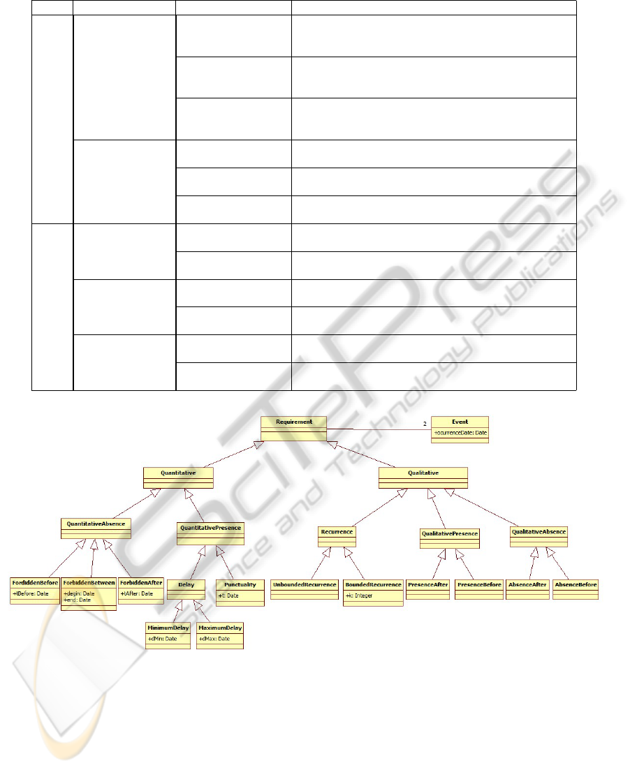
Table 1: Temporal Requirement’s Taxonomy Descriptions.
Class Category Pattern Name Description
Quantitative
QuantitativeAbsence
Forbidden Before
R ensures that an event (E
mon
) must never occur before a minimum
T
be f ore
(time unit over E
Re f
). S|=R is true if this event does not occur
before T
be f ore
.
Forbidden After
R ensures that an event (E
mon
) must never occur after a deadline T
a f ter
(time unit over E
Re f
). S|=R is true if this event does not occur after
T
a f ter
.
Forbidden Between
R ensures that an event (E
mon
) must never occur between a temporal
interval ]t
Begin
; t
End
[ (over E
Re f
). S|=R is true if this event does not
occur between temporal interval ]t
Begin
; t
End
[.
QuantitativePresence
MinimumDelay
R ensures that an event (E
mon
) must occur after a minimum time T
min
(time unit over E
Re f
). S|=R is true if this event occurs after T
min
.
MaximumDelay
R ensures that an event (E
mon
) must occur before a deadline T
max
(time unit over E
Re f
). S|=R is true if this event occurs before T
max
.
Punctuality
R ensures that an event (E
mon
) must occur at one punctual date t (time
unit over E
Re f
). S|=R is true if this event occurs at the t date.
Qualitative
Recurrence
UnboundedRecurrence
R ensures that an event (E
mon
) must occur infinity of time. S|=R is
true if this event occur.
BoundedRecurrence
R ensures that an event (E
mon
) must occur k time. S|=R is true if this
event occur k time.
QualitativePresence
PresenceAfter
R ensures that an event (E
mon
) must occur after E
Re f
have been de-
tected. S|=R is true if this event occurs at least once after E
Re f
.
PresenceBefore
R ensures that an event (E
mon
) must occur before E
Re f
. S|=R is false
if E
Re f
occurs before E
mon
.
QualitativeAbsence
AbsenceAfter
R ensures that an event must never occur after E
Re f
. S|=R is true if
this event does not occur.
AbsenceBefore
R ensures that an event (E
mon
) must never occu before E
Re f
r. S|=R
is true if E
mon
does not occur before E
Re f
.
Figure 1: Temporal Requirements Classification.
Temporal Logic Description: Contains mappings
of the property monitored by the pattern to
TCTL for each of the four defined scopes. We
chose TCTL since it allows quantitative temporal
properties expression.
4 TRANSFORMATION
APPROACH
Since the observation patterns’ basis has been intro-
duced, we will discuss now how to use this basis in
the verification process. In practice, once the tempo-
ral requirements for the system under study are iden-
tified and extracted, the appropriate patterns for these
ICINCO 2010 - 7th International Conference on Informatics in Control, Automation and Robotics
48
requirements are selected and instantiated with the
suitable parameters, thus resulting in some SM ob-
servers. Each SM observer monitors an elementary
requirement. The SM observers are then translated
into TA observers. This transformation will be pre-
sented hereafter.
4.1 Transformation Idea
In spite of the number of automated analyzers devel-
oped for TA, these tools suffer from two main lim-
itations: the first is that users must be familiar with
their formal notations. The second is the lack of pat-
terns for high-level system design (hierarchy notion
namely). On the other hand, semi-formal languages,
such as UML SM, are suitable for expressing system
requirements. However, the automatic verification of
these models is unfeasible directly. The temporal re-
quirement verification approach that we propose takes
advantage of the expression flexibility of SM and the
analysis facilities offered by TA formalism.
The various rules of the transformation algo-
rithm we have defined are expressed according to the
Model-Driven Architecture (MDA) approach. MDA
is an initiative and a standard proposed by the OMG,
allowing developers to create systems entirely based
on models. It points out the idea of separation of con-
cerns by unlinking/uncoupling the application logic
from the implementation platforms technology (Weis
et al., 2003).
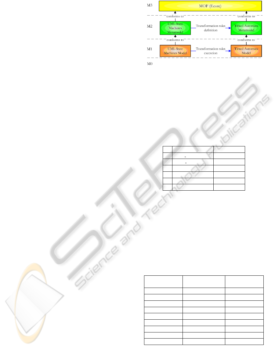
Figure 2 illustrates the use of the MDA four-layer
metamodeling architecture for our transformation;
• The source model (resp. target model) is ex-
pressed according to the source metamodel (resp.
target metamodel),
• The metamodels are defined and expressed ac-
cording to the MOF metametamodel (in our trans-
formation, we used the Ecore metametamodel,
which is the Eclipse implementation of MOF),
• A metamodel is developed for TA. On the other
side, we used the UML metamodel distributed in
the Eclipse framework,
• All the rules are introduced at the metamodel
level,
• The transformation takes a UML SM model as a
source model and generates a TA model with a
corresponding formatted code.
4.2 Time Annotations
Here we use SM as a modeling notation to take advan-
tage of the flexibility they offer. However, since we
strive to obtain an accurate specification, we should
Figure 2: Transformation Approach.
guide the user while introducing the temporal con-
straints. Concretely, we propose a set of timed anno-
tations in order to express the states’ characteristics as
well as the transition guards. Table 2 shows some ex-
amples of them and defines the signification of each
annotation.
Table 2: Time annotations used.
Time annotation Signification
1 at most(T
max
) t≤ T
max
2 at least(T
min
) t≥ T
min
3 after(d) t=d
4 between(T
min
, T
max
) T
min
≤t≤ T
max
5 upper(T
min
) t> T
min
6 lower(T
max
) t< T
max
4.3 Transformation Algorithm
One of the key parts of our method is the translation
of UML SM with time annotations into TA. For sake
of space, we will briefly describe the transformation
rules while giving the source and target element for
each of them in 3. For more details, the reader can
refer to (Mekki et al., 2010).
Table 3: Transformation Rules.
Rule Name Source element:
UML SM
target element:
TA
FromStateMachine StateMachine TA
Simple2Simple State State
Final2State Final Pseudostate State
OR2Automata State Automaton
AND2Automata State Automaton
Trans2Trans Transition Transition
Entry2State EntryAction State
Exit2State ExitAction State
Do2State DoActivity State
The main rule of this algorithm is FromStateMa-
chine rule. This rule is the first one carried out by
the transformation algorithm. It picks elements in
the source model, then calls on other rules to trans-
late the selected elements into TA elements in the tar-
PATTERNS FOR TEMPORAL REQUIREMENTS ENGINEERING - A Level Crossing Case Study
49
get model. Likewise, the called rules behave in the
same way; they select elements in the source model
and call the appropriate rule for transforming them.
For example, the FromStateMachine rule is applied
to elements of type “UML::StateMachine” and trans-
lates them into a “TA::AutomataMachine” element.
Also, different element types are selected and differ-
ent rules are called on in this rule. First, the rule
selects all the UML states. Then for each selected
state, according to its type, the rule Simple2Simple or
OR2Automata or AND2Automata is called on. Sec-
ondly, it translates the “UML::Transition” elements
by invoking rule Trans2Trans. Also, this rule deals
with another element type, the “UML::Pseudostate”,
by invoking some other rules such as Final2State.
This internal transformation process is the same
for all the rules; each rule transforms the source ele-
ment into the target one. Then, it selects subelements
of the source element and calls on the appropriate rule
to transform them.
4.4 Verification Process
Once our observation patterns’ basis is implemented,
we introduce a verification process based on this ba-
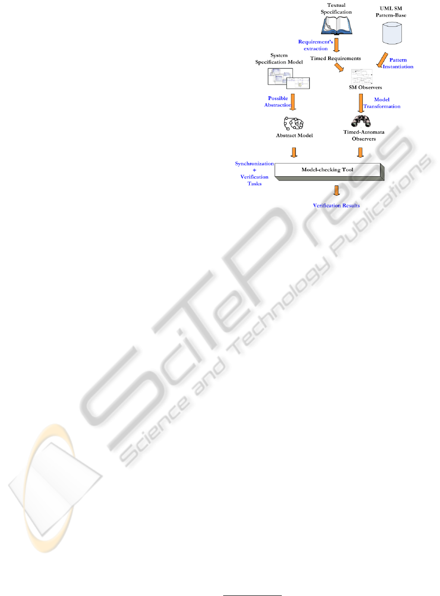
sis. This section will outline the global architecture
of our approach. The architecture is depicted graphi-
cally in Figure 3 (Mekki et al., 2009).
Concretely, our approach is composed of four pro-
cesses: first, temporal requirements for the system un-
der study are identified and extracted. Second, the
appropriate patterns for these extracted requirements
are selected and instantiated with the suitable param-
eters. This second process results in some SM ob-
servers. Each SM observer corresponds to an elemen-
tary requirement. Third, the SM observers are trans-
lated into TA observers. In parallel and in the same
way, the specification under study (SM model with
time annotations) is abstracted and translated into a
TA model. The translation from the UML SM to TA
is performed using the MDA model transformation
technique as shown previously.
Finally, the generated TA are synchronized with
the formal system’s specification model (TA) to gen-
erate a global model holding both the system speci-
fication and the requiements’ monitoring. Thus, the
verification task is reduced to an error-state reachabil-
ity search on the obtained global model.
Figure 3: Method Global View.
5 CASE STUDY
5.1 Case Study Description
A classical automatic level crossing system is com-
posed of several modules. The local control sys-
tem which manages the traffic in the crossing area,
a pair of barriers (gate), traffic lights whose role is to
alert and prevent road users from entering the cross-
ing zone and a train-sensing module which monitors
trains approaching/leaving (Ghazel, 2009). The sub-
systems mentioned above execute in parallel and syn-
chronize through events.
Several requirements
∗
are given in textual speci-
fication in Figure 4. Next, using this textual specifi-
cation, we will show how patterns are used to express
and monitor requirements.
5.2 Using Patterns
For sake of space, only two requirements will be
checked on the basis of the textual system specifi-
cation. For each requirement, formalization is intro-
duced using the defined generic template. First, a tex-
tual description of the requirement is presented, fol-
lowed by an intuitive graphical representation in the
shape of an UML SM (SM patterns). Then, a defi-
nition using our structured English grammar is given
and finally a temporal logic expression is used to ex-
press formally the requirement. 1) The 1
st
require-
∗
http://www.dagstuhl.de/fileadmin/redaktion/Programm/Seminar/
07241/07241.CaseStudy.pdf
ICINCO 2010 - 7th International Conference on Informatics in Control, Automation and Robotics
50
1. “. . . As long as an approaching train runs over the activation
sensor the sensor shall generate an occupied signal. When the last
axle of the train has traversed the activation sensor it shall
generate a free signal again. If the control unit receives an
occupied signal from the activation sensor in the unsaved mode, it
will enter the saving mode and gives the command to turn on the
yellow lamp of the set of lights. Three seconds after entering the
saving mode the control unit has to give the command for
switching off the yellow lamp and turning on the red lamp. . . ”
2. “. . . By entering saved mode the controller shall switch on the
supervision signal to show signal aspect LC1, which means to turn
on the blinking light. Twelve seconds after the system has entered
the safed mode it must start to lower the gate. The activity of
lowering or raising the gate must not last longer than six seconds
from one end position to the other. When the gate has reached the
lower end position within the six seconds interval the control unit
will enter the mode saved and gates closed. . . ”
Figure 4: Specification Example.
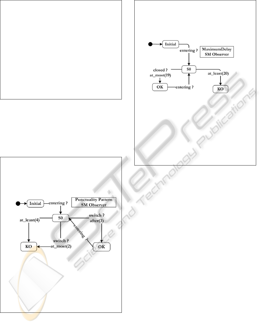
ments states that three seconds after receiving the en-
tering signal, the controller should send command for
switching lights. This requirement consists in a punc-
tuality property (Figure 5) of 3 seconds between en-
tering signal and switch signal.
Punctuality Pattern
Pattern Name: Punctuality
Textual Description: The Punctuality pattern is used to check that a
given event execution is delayed by exactly d time units relatively
to a given reference.
UML SM Diagram:
Structured English:
Scope “switch” must occur exactly at “3” tu over “entering”.
Temporal Logic description:
Globally: AG[receive(entering) ⇒ AF
=d
receive(switch)]
After E
a
: AG(E
a
→(EG[receive(entering) ⇒ AF
=d
receive(switch)]))
Before E
b
: A((AG[receive(entering) ⇒ AF
=d
receive(switch)]) U E
b
)
Between E
b
and E
e
:
P=AG[receive(entering) ⇒ AF
=d
receive(switch)]
AG((E
b
∧¬E
e
)→(P) U E
e
)
Figure 5: Punctuality Pattern.
2) The 2
nd
requirement states that the command sig-
nal closed should be detected at most 19 seconds after
entering signal. This requirement consists in maxi-
mumdelay property (Figure 6) of 19 time units be-
tween entering and closed signals.
MaximumDelay Pattern
Pattern Name: MaximumDelay
Textual Description: The MaximumDelay pattern is used to check if
event execution is delayed by at most a given value ` time units
from a given reference. This value ` should be in [0, T
max
] interval.
UML SM Diagram:
Structured English: Scope “closed” must occur Before a delay of
“19” tu over “entering”.
Temporal Logic description:
Globally: AG[receive(entering) ⇒ ¬closed U
≤19
receive(closed)]
After E
a
:
AG(E
a
→(AG[receive(entering) ⇒ (¬closed U
≤19
receive(closed))]))
Before E
b
:
A((AG[receive(entering) ⇒ (¬closed U
≤19
receive(closed))]) U E
b
)
Between E
b
and E
e
:
P=AG[receive(entering) ⇒ (¬closed U
≤19
receive(closed))]
AG((E
b
∧¬E
e
)→(P) U E
e
)
Figure 6: MaximumDelay Pattern.
5.3 Verification
The above step consists in instantiating the appropri-
ate patterns in order to obtain observers for the ex-
tracted requirements. These observers are then trans-
lated into TA models to be synchronized with the sys-
tem specification. The verification process consists in
examining the reachability of the KO-states within the
observers. The verification of our case study is carried
out using the UPPAAL model checker.
6 CONCLUSIONS
In this paper, we have presented a model-based
method applicable to formal specification and valida-
tion of time-constrained systems. The approach uses
a set of observation patterns that we have established
and which act as watch-dogs for the defined temporal
requirements. Each pattern has been defined using a
standard template we developed. Using patterns of-
fers genericity and reusability.
On the other hand, we have developed a trans-
formation algorithm to translate SM with time anno-
tations into TA. The aim being to make a basis for
the verification process. For this purpose, we have
PATTERNS FOR TEMPORAL REQUIREMENTS ENGINEERING - A Level Crossing Case Study
51

introduced a TA metamodel using an extended def-
inition of the original TA definition given by (Alur
and Dill, 1994) (for briefness reasons, the TA meta-
model description is omitted in this paper). Once the
relationships (transformations rules) between UML
SM metamodel elements and TA metamodel ele-
ments are defined, we expressed them in the QVT
(Query/View/Transformation) language, defined by
the OMG as the standard for the transformation phase.
Then we used QVTo -an Eclipse Plugin- to run the al-
gorithm.
Processing the verification upon the TA observers
synchronized with the system specification reduces
the verification task to a reachability analysis of the
KO-nodes within the observers.
Validation of the model transformation algorithm
we have developed is a key issue to ensure the correct-
ness of our approach. Hence, a rigorous validation
step is still needed where several properties should
be checked such as; syntactic and behavioral equiv-
alence, termination and confluence (K
¨
uster, 2006).
Based on the structured English grammar we have
developed, a prototype tool which offers interest-
ing facilities in terms of requirements specification
and requirements consistency-check has been imple-
mented. A subsequent step will be to extend this tool
with a new module which automatically instantiates
observers for the entered requirements using the ob-
servation patterns repository.
REFERENCES
Alur, R. and Dill, D. (1994). A theory of timed automata.
Theoretical Computer Science, 126:183–235.
Dhaussy, P., Pillain, P.-Y., Creff, S., Raji, A., Traon, Y. L.,
and Baudry, B. (2009). Evaluating context descrip-
tions and property definition patterns for software for-
mal validation. In 12th ACM/IEEE International Con-
ference, MODELS 2009, Denver, Colorado, USA.
Dong, J. S., Hao, P., Qin, S., Sun, J., and Yi, W. (2008).
Timed automata patterns. IEEE Transactions on Soft-
ware Engineering, 34(6):844–859.
Dwyer, M. B., Avrunin, G. S., and Corbett, J. C. (1999).
Patterns in property specifications for finite-state ver-
ification. In In Proceedings of the 21st International
Conference on Software Engineering, pages 411–420.
Gamma, E., Helm, R., Johnson, R., and Vlissides, J.
(1995). Design Patterns : Elements of Reusable
Object-Oriented Software. Addison Wesley.
Ghazel, M. (2009). Using stochastic petri nets for level-
crossing collision risk assessment. IEEE Transaction
on Intelligent Transportation Systems, 10(4):668–677.
Ghazel, M., Toguyni, A., and Yim, P. (2009). State ob-
server for DES under partial observation with time
petri nets. Journal of Discrete Event Dynamic Sys-
tems, 19(2):137–165.
Konrad, S. and Cheng, B. (2005). Real-time specifica-
tion patterns. In Proceedings of the 27th Interna-
tional Conference on Software Engineering (ICSE05),
St Louis, MO, USA.
K
¨
uster, J. M. (2006). Definition and validation of model
transformations. Software and System Modeling,
5(3):233–259.
Larsen, K., Pettersson, P., and Yi, W. (1997). Uppaal in a
nutshells. International Journal of Software Tools for
Technology Transfer, 1(1/2):134–152.
Mekki, A., Ghazel, M., and Toguyeni, A. (2009). Vali-
dating time-constrained systems using uml statecharts
patterns and timed automata observers. In 3rd Inter-
national Workshop on Verification and Evaluation of
Computer and Communication Systems Vecos09, Ra-
bat, Morroco.
Mekki, A., Ghazel, M., and Toguyeni, A. (2010). Time-
constrained systems validation using mda model
transformation. In Proceedings of the 8th ENIM IFAC
International Conference of Modeling and Simula-
tion, Hammamet, Tunisia.
Nascimento, F., Oliveira, M., and Wagner, F. (2009). For-
mal verification for embedded systems design based
on mde. In IESS’09 - International Embedded Sys-
tems Symposium, Friedrichshafen, Germany.
Schmidt, D. C. (2004). Model driven engineering. IEEE
Computer, 23(2):25–31.
UML (2009). Unified Modeling Language Specification,
Version 2.2. OMG.
Weis, T., Ulbrich, A., and Geihs, K. (2003). Model meta-
morphosis. IEEE Software, IEEE Computer Society,
20(5):46–51.
Yovine, S. (1997). Kronos: a verification tool for real-time
systems. International Journal of Software Tools for
Technology Transfer, 1(1/2):123–133.
ICINCO 2010 - 7th International Conference on Informatics in Control, Automation and Robotics
52
