SELF DEPLOYED ROBOTIC NETWORK FOR LONG RANGE
SEMIAUTOMATIC OPERATION
Robotics Network for Distance Data Connection, Areal Signal Connection
Coverage or Areal Data Acquisition
Tomas Solarski, David Vala and Jiri Koziorek
Department of Measurement and Control, VŠB-Technical University of Ostrava, 17. Listopadu 15, Ostrava, Czech Republic
Keywords: Robot, Network, Communication, Data, Acquisition, Sensor, Control, Motion.
Abstract: This paper covers questions about long distance communication in a difficult hazardous environment.
Distant communication is presented via number of robotics carriers determined to link communication
between a centre of control and a remote controlled deployed robot in hostile area or gather data from
certain area. The robotic network is autonomous cooperative system of vehicles to provide data connection
for the tele-operated deployed robot for example in rescue mission. This robotic network acts autonomously
and reacts with surroundings background to guarantee data connection. Two main issues are presented: the
data communication and the robotic carrier. Communication can be created by own wireless system carried
on robots or use accessible communication such Wi-Fi/Ethernet in urban areas to use the installed networks
in buildings to increase a capability of network. The robotics carriers will be realized as modular system
with capability to modify each main part of carrier to fit specific environment. Basic construction of the
robotic carrier is traction unit with basic frame with motor(s) and lithium based batteries, control unit based
on MCU/DSP controller and internal sensor unit with capability to install another set of the external sensors.
To provide positions of the carriers to on operator a visualisation of their position is planned by Goole Earth
like application.
1 INTRODUCTION
Nowadays advances in embedded systems
computations and communication technologies
provide support for the cooperative multivehicle
systems – mobile robots.
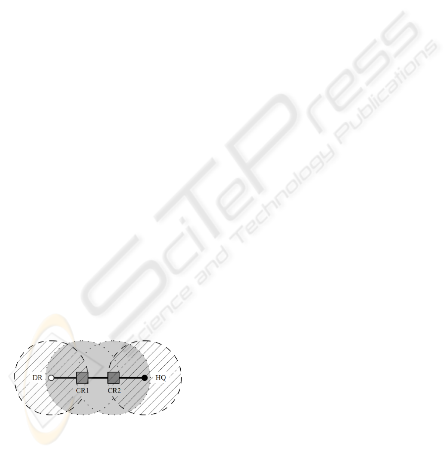
Figure 1: Extended communication by two repeaters.
Mobile robotics are part of our nowadays life,
there is an amount of usage of them in explicit areas.
Part of robots is designed to work in difficult areas
dangerous to human. Environments like areas after
or under natural (flood, wildfire) or industrial
(chemical, mine) disasters could cause a human
injury or even lost of life. They are available only
for specific robotic unit equipped by specific tools,
sensors or both to perform a search and rescue
mission or gather data of the situation.
Employment of such robot can be complicated
due to limitations of signal connection, to obtain an
extended range. The communication problem can be
caused by density of urban areas, difficult mountain
landscape, complicated shaft net in mines, radio
power limitations etc. Solving extended
communication range from control centre to
deployed robot can be via system of mobile signal
repeaters carried on auxiliary robots (robot carrier).
Robot carriers can act autonomously and perform
several nets topology to secure connection to
deployed robot or perform data acquisition from area
depended on sensor equipment on the robot carrier
and its count. Figure 1 shows simple line topology to
extend radio communication distance between
control centre (HQ) and deployed robot (DR) by two
robots carrying wireless repeaters (CR).
427
Solarski T., Vala D. and Koziorek J. (2010).
SELF DEPLOYED ROBOTIC NETWORK FOR LONG RANGE SEMIAUTOMATIC OPERATION - Robotics Network for Distance Data Connection, Areal
Signal Connection Coverage or Areal Data Acquisition.
In Proceedings of the 7th International Conference on Informatics in Control, Automation and Robotics, pages 427-432
DOI: 10.5220/0002950504270432
Copyright
c
SciTePress
Robot carrier himself is completed like
multipurpose kit containing several independent
units to rebuild carrier and fit it to specific area.
Carrier kit contains a wireless communication unit, a
control unit and a traction unit (chassis), optionally a
sensor unit to gather interest data. Each robotic
carrier’s unit will act like a distributed system with
control subsystem secondary to control unit.
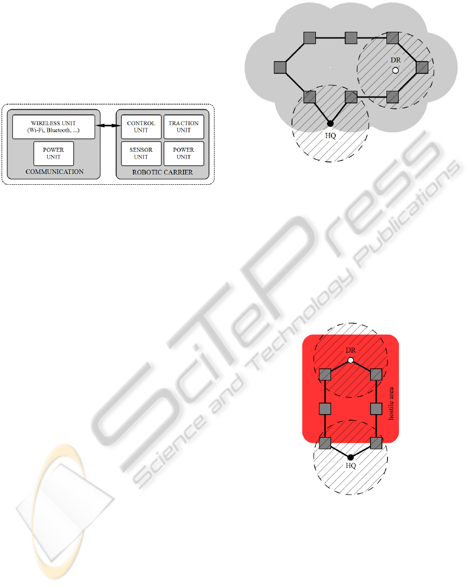
Figure 2: Block scheme of robot.
2 COMMUNICATION
There are many important parts and tasks to develop
in this project. One of the most important parts is to
develop open radio network for communication
between service robot(s) and base station. Because
usual teleoperator or a service robot use several
communication channel to data exchange separated
by purpose or origin of data (camera / video, control,
telemetry, payload, etc).
To avoid collisions with this amount of data
interface with different, frequency, bandwidth, data
throughput rate, range and so on, we establish
common interface to all robot internal system as
well as transferred data to Ethernet. It causes that
you can connect any existing or future device
directly or through simple bridge whereas most of
them are commercial accessible and also has not any
influence to existing communication inside robots
system as e.g. the control system and its peripheries.
There is possible to transfer control command to the
communication unit, telemetry data as well as
multiple real time still or motion picture in this
solution.
This kind of plug and play system for
communication subsystem allows to mount the best
suitable communication unit directly before robots
mission and to use its all features during operation.
As main communication standard we use cheep
IEEE802.11b/g system which has sufficient data
throughput and range for most of the robot
applications. Also the using of modules with
GSM/GPRS/EDGE is possible when they are
available or robots operate on wide area.
Figure 3: Areal signal covering.
Data exchange with operators or between service
robots behind direct radio visibility during rescue
and security mission is necessary to be all the time.
We design semiautonomous robotics retranslation
unit to solve this problem. This robotic mobile
repeater can be carried on main robots and deployed
in situation when direct communication is unstable
or not reliable. There is a new issue to solve – how
to organize the radio network to have the most
optimal area coverage.
Figure 4: Doubled connection to deployed robot.
We have designed several basic scenarios for
testing different type of radio signal inaccessible
conditions. This model could be described as line,
area, path, and circle coverage of hostile area. And
in this model we are looking for best points to
deploy the mobile repeater carriers. Advantage of
repeater mobility could be exploited when
surrounding condition are changed or is necessary
adapted network topology. Higher mobility and
climb ability in e.g. “Leg’s” version of repeater
ICINCO 2010 - 7th International Conference on Informatics in Control, Automation and Robotics
428
allows finding better position to retransmitting data
from source to destination. Some variation of
scenario describes backup communication line with
dual line of repeater. This is done for safety reason
when noise, lost signal or failure causes a
termination of one repeater carrier.
Second task is long term operation of service
robots in wide area in cooperation with several
mobiles robots and fixed station. This mode
describes coverage of area with size over units or
tens of square kilometres equipped of partial
working infrastructure like Wi-Fi, GSM or private
radio network. Robots communicate trough real
dynamic reconfigurable heterogeneous network over
TCP/IP protocol in this task. However it seems that
small mobile repeater have no advantage and place
in this scenario, relative small and cheap mobile
robot carrier with cooperation with main services
robots can keep well coverage of wide area radio
network. Mobility of repeater carrier can help them
to survive difficult conditions. Sensor equipped
mobile repeater also provides support to
environmental analyses not only useful for routing
option.
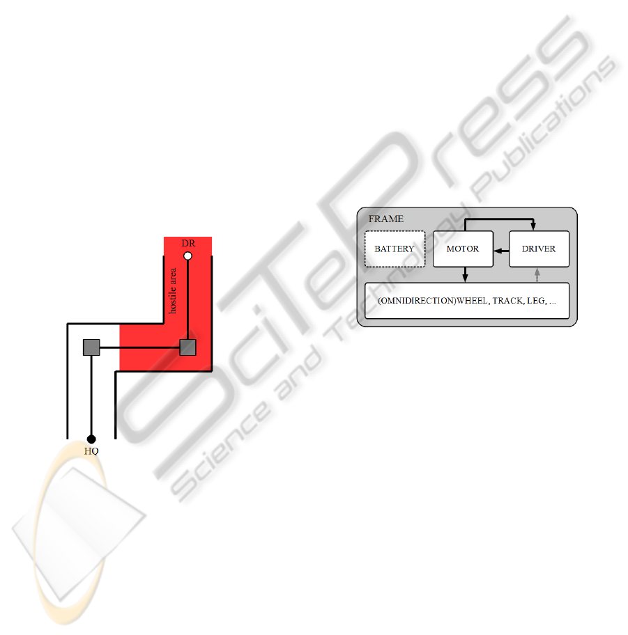
Figure 5: Using of two carried repeaters in urban or mine
area.
3 ROBOTIC CARRIER
To provide a positional layout of signal repeaters,
autonomous carriers are needed. In our case we will
work with solution based on service robotics
modular system. Modular means that key parts of
the robotic carrier are interchangeable to fit specific
area of interest.
Main idea is to split solution of robotic carrier
into several units and solve them separately. Basic
robot can be divided into units: traction, power
supply, control and sensor. The traction is mostly
entire mechanical problem due to containing frame
(chassis) of robot. The chassis is depending on the
traction system. Several traction solutions can be
used mainly for indoor or outdoor purpose.
3.1 Traction Unit
By the traction unit we understand a subsystem of
robot that provides movements and creates a frame
for other parts of the robot. The traction unit
contains: frame, gearing, motor(s) and driver
(electric), eventually battery.
Simplified block scheme on Figure 6 shows a
main part of the traction unit including a battery.
Due to a lot of robot’s construction possibilities the
selection of battery is depended on traction.
Nowadays we have to use battery pack based on
Lithium due to very good power to weigh ratio and
also a maximum current capability, like Li-Pol and
others. Size of traction is related to battery capacity
and nominal voltage (number of cells).
Figure 6: Block scheme of traction unit.
The frame of the robotic carrier is basic
construction set for entire robotic system. It has to
be light and solid and also suitable for areas of
interest. Most used traction on robots nowadays is
wheels and tracks (tank under cart). Wheels are very
simple to control and robot can move in high speed.
On the other hand tracks are slow but robust and can
pass terrain with more obstacles.
There are several main environments which
influence selection of suitable gears for robot.
Generally there are indoor and outdoor. By outdoor
we mean only land terrain.
Indoor conditions are represented by short
distances and flat surfaces where the main obstacle
is stairs. Capability to pass stairs can split indoors
robots into two areas. The stairs passing robots have
more complicated construction and they are similar
as the outdoors robots. Indoor environment provide
ideal surface to movement of robot with special
traction based on omni directional wheel or walking
robots. The omni-wheel is a segmented wheel with
SELF DEPLOYED ROBOTIC NETWORK FOR LONG RANGE SEMIAUTOMATIC OPERATION - Robotics Network
for Distance Data Connection, Areal Signal Connection Coverage or Areal Data Acquisition
429
capability of two axis movement. The robots based
on the omni-wheel can contain common wheels
(two) and be completed with omnidirectional (third)
to improve turning of the robot. Also a fully
omnidirectional equipped robot can be possible, for
example a three wheel robot. Movement of this kind
of traction is by a various speed of omni-wheels, so
robot can change its direction based on the actual
speed of omni-wheels.
The indoor environment can be also very good
for walking robots without special abilities to control
balance on inclined or another complicated surfaces.
Segment of walking robots are humanoids - but
there are problems with balance and speed of them
and so there are not very suitable. More useful
robotic traction is based on spider like chassis – 6 or
8 legs. This traction unit provides stability without a
complicated balancing system but still has limited
speed due to complicated leg’s movement. Also a 6
or 8 legs robots have to be equipped with a number
of servomechanisms regardless to number of joints
on each leg.
Pure walking robots are designated to indoors
applications but there can be hybrid solution based
on combination of wheel and leg. This solution
provides a speed from wheels and agility from legs.
The outdoor conditions are more complicated
and for the purpose of robotic network are more
probable. Outdoor applications could be majority for
robot’s movement. Suitable traction for outdoor
application is wheels (like in car) and tracks (tank).
This kind of traction is very suitable for terrain,
roads even in buildings and stairs. Outdoor designed
robots can easily be used also in buildings even to
climb stairs.
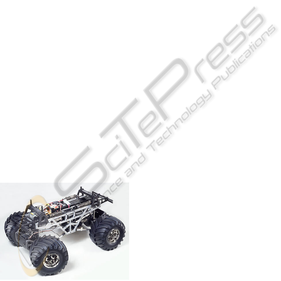
Figure 7: Tamiya TXT-1.
Regarding to high efficiency and speed of wheel
based traction this kind of robot is very suited for
outdoor application and to carry a wireless
connection unit. Figure 7 presents a system from RC
car which is very good for outdoor robot. This
traction provides two DC motors for driving all four
wheels (4x4) on entirely suspended base. Also both
axletrees are steered. Tires are adjusted to work in
complicated terrain.
Movement of the traction is based on electric
motor of any kind. There is also gas-engine where
endurance is enlarged, but this has to be more
serviced and control of gas-engine is more
complicated, so we will work only with DC or EC
motor.
Part of traction unit is a driver for electric motor.
Construction of driver is very similar even we have
DC or BLDC motor. The driver is based on circuits
called half-bridges and due to the DC or BLDC there
are two or three half-bridges in driver. Half-bride is
junction of two power switches which can amplify
logic signal to provide power supply battery level
and can provide required current. In mobile robotics
are used almost only MOSFET based constructions.
Advantages of MOSFET are very low power losses
and high frequencies of work with minimum of
driving energy. N-MOSFET work like ideal power
switch and is widely used in power electronics like
motor drivers with low voltage (<100V). The driver
will be equipped with his own control to provide
close loop control of motor. Based on traction
system there can be feedback from sensor on shaft of
motor or on a wheel, also sensors on legs etc.
Control system in traction, based on MCU will
communicate with his superior the Control unit of
the carrier.
3.2 Power Supply Unit
Power supply or battery for the robotic carrier is
very depended on the traction unit. The indoor and
outdoor application may be very separate of each
other in range and online time and also in a
size/weight of robot. The battery pack will be then
different. So we can think about including power
supply to traction unit and have it together in kit. In
this paper we will be talking about power supply
unit as separate part of the system. But in the robotic
carrier kit will be part of traction.
Batteries which can be used in mobile robotics
are basically based on Lithium. Thinking about
NiMH, SLA or even NiCd is obsolete. Advantage of
Lithium based cells is power to weigh ratio and high
current capability (Li-Pol). Also a minimum looses
of energy stored that make robot less needed of
service. Main disadvantage on Li-xxx is precise
ICINCO 2010 - 7th International Conference on Informatics in Control, Automation and Robotics
430

charging and watch on discharging to not outrun a
minimum voltage limits. Due to this we need to
precise charging with balancing/limiting system and
when used (discharged) a system to count energy
and estimate remaining capacity (to stop discharging
in right time) and also watch limits especially
minimum voltage per cell.
Power supply unit then contains a basics
subsystems like: battery cells, protective circuits and
fuel gauge. The protective systems are used in
charging of series of cells and balance variance of
each cell (capacity is not ideally similar, one cell is
fully charged faster than another). Fuel gauge
system based on MCU counts energy stored in cells
and estimate remaining energy which can be
provided. Method is based on simple current and
time measurement and it can be determined a
quantum of current which flows from battery to load
(motor). Also current when charging can be
measured (will be negative, current flows back) but
there is a problem with protective systems because
basic protective system change redundant charging
energy into heat.
In mobile robots for outdoor application we can
estimate a 7 to 10 cell needed to provide power
supply up to 30-42V with continuous discharge
current of 10 to 15A. This make an output power in
range 300 to 600W which is ideal for mobile wheel
based robot with traction based on system from
Figure 7. For the indoor robot same cell can be used
but only two or three will be needed.
Power supply unit is slave to the control unit
(master on the bus) and contain separate control to
measure capacity of power cell(s) and can estimate
and report it to control unit.
3.3 Control Unit
Main unit in robotic carrier is the control unit. This
unit have to decide how to ensure data connection,
how to get to position, to drive traction unit and to
communicate with others carriers and to establish
connection from control centre to deployed robot.
Entire control of robotic carrier is distributed
because all of units have their own control by MCU.
The control unit act like a master on bus via which
all MCUs are connected together. Preferred bus on
such mobile robot is LIN, RS485 or even CAN
based on required speed and data security.
The control unit depends on complexity of
needed solution from algorithms. Based data are
gained from sensor unit and from communication.
The control unit calculates a position to move and
control movement by sending required speed to
closed loop control of motor in traction unit.
Basically this can be covered by some newer MCU
with 32 bit core to obtain a real time solved
problems and results.
Power supply to control unit is from power unit,
so there is a power supply shared with motor on the
other hand a wireless unit have its own because
primary function is to provide data connection.
3.4 Sensor Unit
In mobile robotics we can split sensors into two
groups. Internal sensors are used to ensure a basic
function of the robot. Typically internal sensors are
incremental rotary sensors in motor (traction unit) or
sense resistors in battery (power unit). These sensors
are used to operate a basic system of robot. In the
other hand external sensors are used to contact robot
with his exterior, robot can operate self without it
and this external sensors determine the basic type
and purpose of the robot.
Internal sensors are then on unit which control
basic function of the robot. Sensor unit contains
external sensors to gather data from surrounded area
of robot. Because a primary function of robot is to
carry a wireless system and establish connection to
deployed robot a sensor unit is basically equipped
with sensors to obtain a global position of robot and
to provide them to control unit to establish right
network topology. Also safety ability has to be
implemented to avoid contact robot with obstacle or
to do not injure humans. Basically, the robot needs a
set of tactile sensors to avoid obstacles. Tactile
sensor is contact or contactless, where the simplest
contact tactile sensor is a switch, but this is not very
useful because a short range of operation. More
useful sensors are contactless based on ultrasonic
sensors or infrared optical sensor, both work like
range finder so we can find an obstacle and also we
can estimate range of it.
In indoor application of carrier a network
topology can be determined basically on odometer
(data from traction unit). Indoor due to short ranges
and covering sky a global data cannot be provided
and precise admeasurements have to be used. So
there we need to know a start position of each carrier
to work with this offset of position.
Additional sensors can be used to gather more
data from area where carrier robot is used. This will
work as additional function and area where are
robotics carriers deployed can be better monitored
than only with deployed robot. There can be used
simplest sensors to measure temperature, pressure
sound waves, chemical materials in air etc.
SELF DEPLOYED ROBOTIC NETWORK FOR LONG RANGE SEMIAUTOMATIC OPERATION - Robotics Network
for Distance Data Connection, Areal Signal Connection Coverage or Areal Data Acquisition
431

4 VISUALIZATION
The entire system needs a visualization system to
provide human-machine interface, to simplify using
and maintenance. Each system has specifics
demands for visualization and for system described
above is very important except of standard telemetry
data also position data of each unit as well as give to
operator overview and knowledge of terrain (etc.)
where robots operate. For this purpose is useful
include part of geographic information system to
operator control panel to access terrain map data. It
could be dynamically refilled and updated by e.g.
aerial photography, laser scan or other robots sensor
data or data from mobile repeater such as
temperature, chemical sensor or camera.
“Wide are” scenario has huge requirement for
GIS data source which could be very expensive. For
this reason we are use public GIS source like Google
Earth. This makes possible to visualize robots,
repeaters and other position in 3D maps and terrain
model. Big advantage of this system is possibility
dynamic updating visualized data. It simplifies
maintenance of whole system and allows online
publishing of e.g. environmental data for community
or government usage; depend on mission and
devices type.
5 CONCLUSIONS
This work on mobile robotic network is basically in
phase of prototype development. Presented
information will be taken under test and will show
us possibilities of next development and serves us as
guide to how to continue on this project. Basic idea
was to enlarge the range of wireless system to our
robot. Nowadays we have knowledge on
constructing mobile robots and this work is based on
prototypes of them. We believe that our work will
provide a functional prototype of robotic network to
use in emergency and rescue operations.
Robotics system has also feature to join several
branches of technical development. Traction is based
on mechanical engineering, network is based on
communication solutions, sensors and control unit
need to be solved by electronics and finally
visualization is based on computer programming.
ACKNOWLEDGEMENTS
This work is supported by grant of the Grant Agency
of the Czech Republic GA102/08/1429 - Safety and
security of networked embedded system
applications.
REFERENCES
Cruz, D., McClintock, J., Perteet, B., Orqueda, O., Cao,
Y., Fierro, R., 2007. Decentralized cooperative
Control – A multivehicle platform for research in
networked embedded systems. In IEEE Control
Systems Magazine, [internet] June. Available at :
http://www.ece.unm.edu/faculty/rfierro/papers/2007/
Marhes_CSM-Published.pdf [Accessed 12 December
2009].
Sanfeliu, A., Hagita, N., Saffiotti, A., 2008. Network robot
systems. In Robotics and Autonomous Systems,
[internet]. Available at:
http://citeseerx.ist.psu.edu/viewdoc/download?doi=10.
1.1.140.558&rep=rep1&type=pdf [Accessed 15
December 2009]
Kárník, L., 2002. Lokomoční ústrojí mobilních robotů pro
nestrojírenské aplikace. In Automa, [internet] July.
Available at: http://www.odbornecasopisy.cz/index.
php?id_document=28494 [Accesed 18 December
2009]
Solarski, T., Musil, K., Janckulík, D., Vala, D., 2008.
Robotic platform remote controled by enhanced
wireless technology. In 8th International Scientific –
Technical Conference PROCESS CONTROL 2008.
ISBN 978-80-7395-077-4
Stankovič, J., Vala, D., 2008. Data Acquisition by
heterogeneous mesh networks in early warning
systems. In 8th International Scientific – Technical
Conference PROCESS CONTROL 2008. ISBN 978-
80-7395-077-4
ICINCO 2010 - 7th International Conference on Informatics in Control, Automation and Robotics
432
