
CONTROL STRATEGY OF CONSTANT MILLING FORCE
SYSTEM AND METAL REMOVAL RATE MAXIMIZION
Franc Cus, Joze Balic and Uros Zuperl
Faculty of Mechanical Engineering, University of Maribor, Smetanova 17, 2000 Maribor, Slovenia
Keywords: Adaptive Force Control, Neural Control Scheme, Machining, End-milling.
Abstract: An adaptive control system in conjunction with off-line optimization is built which controlling the cutting
force and maintaining constant roughness of the surface being milled by digital adaptation of cutting
parameters. In this way it compensates all disturbances during the cutting process: tool wear, non-
homogeneity of the workpiece material, vibrations, chatter etc. The basic adaptive control design is based
on the control scheme (UNKS) consisting of two neural identificators of the process dynamics and primary
neural regulator.
1 INTRODUCTION
The use of computer numerical control (CNC)
machining centers has expanded rapidly through the
years. A great advantage of the CNC machining
center is that it reduces the skill requirements of
machine operators. However, a common drawback
of CNC end milling is that its operating parameter
such as spindle speed or feedrate is prescribed
conservatively either by a part programmer or by a
relatively static database in order to preserve the
tool. As a result, many CNC systems run under
inefficient operating conditions. For this reason,
CNC machine tool control systems, which provide
on-line adjustment of the operating parameters, are
being studied with interest (Balic, 2000). These
systems can be classified into three types: a
geometric adaptive compensation (GAC) system; an
adaptive control optimization (ACO) system; and an
adaptive control constraints (ACC) system.
There is no controller that can respond quickly
enough to sudden changes in the cut geometry to
eliminate large spikes in cutting forces. Therefore,
we implement on-line adaptive control in
conjunction with off-line optimization. The
optimization is performed with algorithm developed
by researchers (Zuperl, 2004) and (Cus, 2003). In
our AC system, the feedrate is adjusted on-line in
order to maintain a constant cutting force in spite of
variations in cutting conditions.
2 NEURAL FORCE CONTROL
STRATEGY
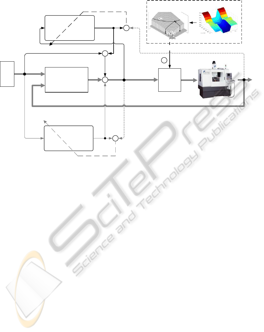
The overall force control strategy consists of
optimizing the feedrates off-line, and then applying
on-line adaptive control during the machining
process. The basic idea of this design is to merge the
off-line cutting condition optimization algorithm and
adaptive force control (Figure 1). Based on this new
combined control system, very complicated
processes can be controlled more easily and
accurately compared to standard approaches. The
objective of the developed combined control system
is keeping the metal removal rate (MRR) as high as
possible and maintaining cutting force as close as
possible to a given reference value. Combined
control system is automatically adjusted to instant
cutting conditions by adaptation of feedrate..
Sequence of steps for on-line optimization of the
milling process is presented below:
1. The recommended cutting conditions are
determined by ANfis software (Mursec, 2000) for
selecting the recommended cutting conditions.
2. Optimization of recommended cutting conditions
by PSO optimization.
3. The pre-programmed feedrates determined by off-
line optimization algorithm are sent to CNC
controller of the milling machine .
4. The measured cutting forces are sent to neural
control scheme.
265
Cus F., Balic J. and Zuperl U. (2010).
CONTROL STRATEGY OF CONSTANT MILLING FORCE SYSTEM AND METAL REMOVAL RATE MAXIMIZION.
In Proceedings of the 7th International Conference on Informatics in Control, Automation and Robotics, pages 265-268
DOI: 10.5220/0002959602650268
Copyright
c
SciTePress
+
F
m
Primary
controller NM-R
DACP software
F
ref
Process inverse
dynamics identifier
NM-2
Process dynamics
identifier
NM-1
F
m
+
-
+
-
+
-
+
+
f
F
ref
f*
f*
f
F
m
F
m
*
External feedback loop
f
Weight adjustment
F
ref
Part-2
Part-3
Part-1
f
CNC
FAGOR
8040-M
f
optimal
Optimal cutting conditions
ANfis software
PSO optimization of
cutting conditions
Recommended
cutting conditions
1
3
2
Figure 1: Adaptive force control combined with off-line optimization.
5. Neural control scheme adjusts the optimal
feedrates and sends it back to the machine.
6. Steps 1 to 3 are repeated until termination of
machining.
The adaptive controller adjusts the feedrate by
assigning a feedrate override percentage to the CNC
controller on a 4-axis Heller, based on a measured
peak force. The actual feedrate is the product of the
feedrate override percentage (DNCFRO) and the
programmed feedrate. The fundamental control
principle is based on the neural control scheme
(UNKS) consisting of three parts (Figure 1). The
first part is the loop known as external feedback
(conventional control loop). The feedback control is
based on the error between the measured (F
m
) and
desired (F
ref
) cutting force. The primary feedback
controller is a neural network (NM-R). The second
part (NM-1) acts as the process dynamics (cutting
dynamics) identifier. The third part of the system is
neural network 2 (NM-2). The NM-2 learns the
process inverse dynamics. The UNKS operates
according to the following procedure. The sensory
feedback is effective mainly in the learning stage.
This loop provides a conventional feedback signal to
control the process. During the learning stage, NM-2
learns the inverse dynamics. As learning proceeds,
the internal feedback gradually takes over the role of
the external feedback and primary controller. Then,
as learning proceeds further, the inverse dynamics
part will replace the external feedback control. The
final result is that the plant is controlled mainly by
NM-1 and NM-2 since the process output error is
nearly zero.
3 EXPERIMENTAL SET-UP
The data acquisition equipment consists of
dynamometer, fixture and software module. The
cutting forces were measured with a piezoelectric
dynamometer (Kistler 9255) mounted between the
workpiece and the machining table. The interface
hardware module consists of a connecting plan
block, analogue signal conditioning modules and a
16 channel A/D interface board (PC-MIO-16E-4). In
the A/D board, the analogue signal will be
transformed into a digital signal so that the
LabVIEW software is able to read and receive the
data. The ball-end milling cutter with
interchangeable cutting inserts of type R216-16B20-
040 with two cutting edges, of 16 mm diameter and
10° helix angle was selected for machining.
The cutting insert material is P10-20 coated with
TiC/TiN, designated GC 1025.
ICINCO 2010 - 7th International Conference on Informatics in Control, Automation and Robotics
266
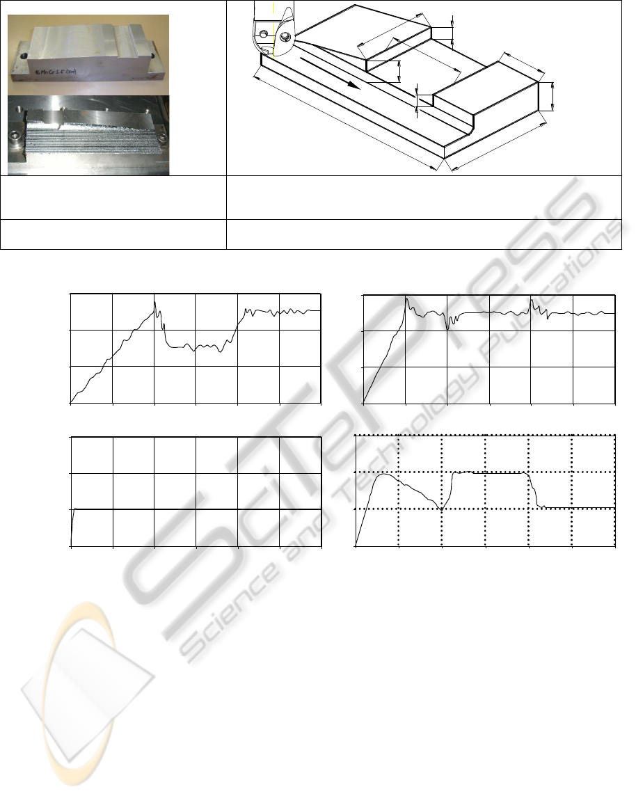
Experiment: Prismatic Workpiece
40
45
5
25
160
60
40
5.8
11
Test_A
Constant feedrate
Cutting conditions: Feedrate: 0.08mm/tooth, Cutting speed: v=80m/min,
Pre-programmed axial depth of cut A
D
=2 mm, Radial depth of cut R
D
=4mm, F
ref
=270N (Kopac, 2002), Result: Figure: 3a.
Test_B
Proposed adaptive control system
Starting feedrate: 0.08mm/tooth, Allowable adjusting rate: 00.8 - 0.20 mm/
teeth, Cutting speed: v=80m/min; Result: Figure: 3b.
Figure 2: Plan of experiment; Cutting conditions for prismatic workpiece.
0
2.5
5
7.5
0 25 50 75 100 125 150
0
2.5
5
7.5
0 25 50 75 100 125 150
0
100
200
300
0 25 50 75 100 125 150
b)a)
F[N]
MRR
[mm
3
/min]
*10
4
0
100
200
300
0 25 50 75 100 125 150
0.00
0.08
0.16
0.24
0 25 50 75 100 125 150
f
[mm/tooth]
A B
C
D
Time [s] Time [s]
15 30 45 60 75 90
15 30 45 60 75 90
0.00
0.08
0.16
0.24
0 25 50 75 100 125 150
A B
C
D
15 30 45 60 75 90
Figure 3: Response of MRR, resulting cutting force and feedrate. a) Conventional milling-Test_A. b) Milling with proposed
adaptive control system-Test_B.
4 PROGRAM DACP
The program for digital adaptation of cutting
parameters (DACP) is developed by software packet
LabVIEW 7. During developing of DACP program
the following requirements are taken into
consideration:
It must established communication between
dynamometer and data acquisition card,
Enable the selecting of measuring channels and
calibration of measuring system,
Establish communication with CNC controls,
Actuate visual and sound signals in case of
cutting tool overloading.
Control panel of DACP consists of three main parts.
Upper part of panel is a monitoring part. Monitoring
part has switches which enable user to define
scanning parameters, measuring ranges, and
accuracy of measuring.
Middle part is a control part. It consists of four
buttons for controlling the milling process.
Reference cutting force and desired surface
roughness is set into the system by two graphical
slides. All important information about
communication state is displayed at the bottom of
control panel. A communication module was
developed to communicate with CNC via an RS-232
serial line.
CONTROL STRATEGY OF CONSTANT MILLING FORCE SYSTEM AND METAL REMOVAL RATE
MAXIMIZION
267

5 EXPERIMENTAL TESTING
OF CONTROL SYSTEM
The stability and robustness of the proposed control
strategy is verified by experiments on a CNC milling
machine for Ck 45 and 16MnCrSi5 XM steel
prismatic workpieces with variation of axial cutting
depth. Details of the experimental conditions and the
dimensions of the workpiece are shown in Figure 2.
Feedrates for each cut are first optimized off-line,
and then machining runs are made with controller
action. The first test is conventional cutting with the
constant feedrate (Test_A). In the second test, the
proposed control system was applied to demonstrate
its performance (Test_B). The parameters for
adaptive control are the same as for the experiments
in the conventional milling (Zuperl, 2003).
Figure 3 is the response of the cutting force and
the feedrate when the cutting depth is changed. It
shows the experimental result where the feedrate is
adjusted on-line to maintain the maximal cutting
force at the desired value.
6 RESULTS AND DISCUSSION
As compared to most of the existing end milling
control systems (Chen, 2006), the proposed adaptive
system has the following advantages: 1. the
computational complexity of UNKS does not
increase much with the complexity of process; 2. the
learning ability of UNKS is more powerful than that
of conventional adaptive controller; 3. UNKS has a
generalisation capability; 4. insensitive to changes in
workpiece geometry, cutter geometry, and
workpiece material; 5. cost-efficient and easy to
implement; and 6. mathematically modeling-free.
Comparing the Figure 3a to Figure 3b, the
cutting force for the neural control milling system is
maintained at about 250N, and the feedrate of the
adaptive milling system is close to that of the
conventional milling from point C to point D. From
point A to point C the feedrate of the adaptive
milling system is higher than for the classical CNC
system, so the milling efficiency of the adaptive
milling is improved.
The time analysis for conventional and adaptive
control system has been curried out. By adaptive
control system of time saving of 40% with one cut
was reached. The complete machining requires 15
cuts; thus machining of a simple workpiece is
shortened for 155 seconds.
The system remains stable in all experiments,
with little degradation in performance. The results
reached are in accordance with the objectives of
researches, according to which the controlled cutting
force must not deviate from the desired value for
more than 10% (Zuperl, 2005).
7 CONCLUSIONS
In this paper, an inteligent control algorithm that
controls feedrate is proposed to regulate the cutting
force. On the basis of the cutting process modeling,
off-line optimization and neural control scheme
(UNKS) the combined system for off-line
optimization and adaptive adjustment of cutting
parameters is built. This is an adaptive control
system controlling the cutting force and maintaining
constant roughness of the surface being milled by
digital adaptation of cutting parameters.
In order to check the applicability of the
adaptive control algorithm, cutting experiments were
carried out under various cutting conditions,
different tool diameters and different work materials.
Experiments have confirmed efficiency of the
adaptive control system, which is reflected in
improved surface quality and decreased tool wear.
REFERENCES
Balic, J., 2000. A new NC machine tool controller for
step-by-step milling. Int. j. adv. manuf. technol. 8, pp.
399-403.
Chen, C., Zhibin, M., (2006). An intelligent approach to
non-constant feed rate determination for high-
performance 2D CNC milling. International Journal
of Manufacturing Technology and Management. pp.
219-236.
Cus, F., Balic, J., 2003. Optimization of cutting process by
GA approach. Robot. comput. integr. manuf., 19 , pp.
113-121.
Kopac, J., 2002. Rezalne sile in njihov vpliv na
gospodarnost obdelave = Cutting forces and their
influence on the economics of machining. Stroj. vestn.
3, pp. 121-132.
Mursec, B., Cus, F., Balic, J., 2000. Organization of tool
supply and determination of cutting conditions. J.
mater. process. Technol., 100, pp. 241-249.
Zuperl, U., Cus, F., 2004. A determination of the
characteristic technological and economic parameters
during metal cutting. Stroj. vestn. pp. 252-266.
Zuperl, U., Cus, F., 2003. Optimization of cutting
conditions during cutting by using neural networks.
Robot. comput. integr. Manuf., 19 ,pp. 189-199.
Zuperl, U., Cus F., 2005. Tool cutting force modeling in
ball-end milling using multilevel perceptron. J. mater.
process. technol.
ICINCO 2010 - 7th International Conference on Informatics in Control, Automation and Robotics
268
