
Detection of Iris in Image by
Brightness Gradient Projections
Ivan A. Matveev
Dorodnicyn Computing Centre of Russian Academy of Sciences
Vavilov str, 40, Moscow, 119333, Russia
Abstract. A method is proposed to detect a human iris location and size in digital
image given some point lying inside the pupil. Method is based on construction of
histogram projections of local brightness gradients and interrelating local maxima
of these histograms as probable positions of pupil and iris borders. Method has
low calculation cost.
1 Introduction
Recognition of human by iris is one of the most demanded biometric technologies.
Algorithm of iris size and position estimation is an essential part of iris registration
systems. At that the following characteristics of algorithm are important:
— reliability (understood as algorithm’s ability to detect iris in images where it
really presents and reject images without iris)
— precision (difference between real and detected iris coordinates is small)
— performance (processing of standard video stream 640 ∗ 480 ∗ 30 fps)
— robustness against noises (including parasite reflections and occlusions by eye-
lids and eyelashes)
— ability to process images obtained by various sensors and in various environment
conditions (one of such requirements here is an ability to detect irises differing in size
by several times).
Since outer borders for both pupil and iris can be approximated by circles with
good precision, circle detection is a central element of any system of iris detection in
image. There are plenty of methods of circle (or circumference) detection implemented
and tested for this task: detecting of mass center of an object selected by thresholding
function [1], detection of a point most remote from borders of such selected object [2],
maximizing of integro-differential circular symmetric operator [3], generalized [4], [5],
[14] and split [6] Hough transform, Hough transform using brightness gradient [7], [8],
brightness gradient projection method [9], paired gradient vectors [10], circular shortest
path construction [11], restoring centers of circles passing through randomly selected
points [12]. But none of these methods does conform to all of the above conditions.
Thresholding and image morphology methods are fast but fail if specular reflection is
present inside pupil. On the other hand, generalized Hough transforms and Daugman’s
A. Matveev I. (2010).
Detection of Iris in Image by Brightness Gradient Projections.
In Proceedings of the Third International Workshop on Image Mining Theory and Applications, pages 45-50
DOI: 10.5220/0002962100450050
Copyright
c
SciTePress

operator give stable results but are calculation intensive and inadequate for real-time ap-
plications. More elaborated later methods [10,11,12] give better robustness/time com-
promise.
However, so far the fact was not employed that iris border contains two circles
(pupil-iris and iris-sclera borders) with interrelated parameters. Synchronous detection
of two circles with parameters subject to certain mutual restrictions, implied by na-
ture of iris allows substantially enhance algorithm characteristics in comparison with
search of single circle. A proposed algorithm of iris location is based on construction
of histograms (local brightness gradient circular projections) and comparisons of their
maxima as possible positions of iris borders.
2 Construction of Circular Projections of Brightness Gradient
As in majority of recognition tasks the problem of iris location can be treated as a prob-
lem of selection of best positions of the two circles from a set of alternatives. These
alternativesare given by positions of maxima of circular projections of brightness gradi-
ent. These projections are constructed relative to an approximate iris center, as detected
in [9].
Input data for the algorithm are monochrome eye image and an approximate po-
sition of eye center. Irises with diameter not exceeding image size (i.e. minimum of
image width and image height) can be detected.
Denote: c = (c
x
c
y
)
T
be a point of approximate center position. Method [9]
guarantees its distance to real pupil center is not greater than half of pupil’s radius. For
simplicity consider this point as a coordinate origin. x = (x y)
T
is a point vector,
b(x) is a brightness (intensity) in this point, g(x) = ∇b(x) is a brightness gradient.
Gradient for discrete digital image is calculated using Sobel mask.
Only points with certain gradient value and direction can belong to iris border. This
set is described by indicator function:
v
U
(x) =
1, if kgk > T
1
and T
2
<
x · g
kxk kgk
and U,
0, otherwise,
(1)
where T
1
and T
2
are thresholds, U is an additional condition selecting a sector (quad-
rant) of the coordinate plane. T
1
is set to reject image noise (including quantization
noise) and is calculated as 6
√
2 max{σ, 2} , where σ is a dispersion caused by the
noise. T
2
is set to include only points where brightness gradient has approximately
same direction as the point vector: T
2
= arccos(π/6). Following conditions are used
for selecting of left, right, upper and lower quadrants respectively:
U =
L : |x| > |y|, x < 0,
R : |x| > |y|, x > 0,
B : |x| < |y|, x < 0,
T : |x| > |y|, x > 0.
(2)
46
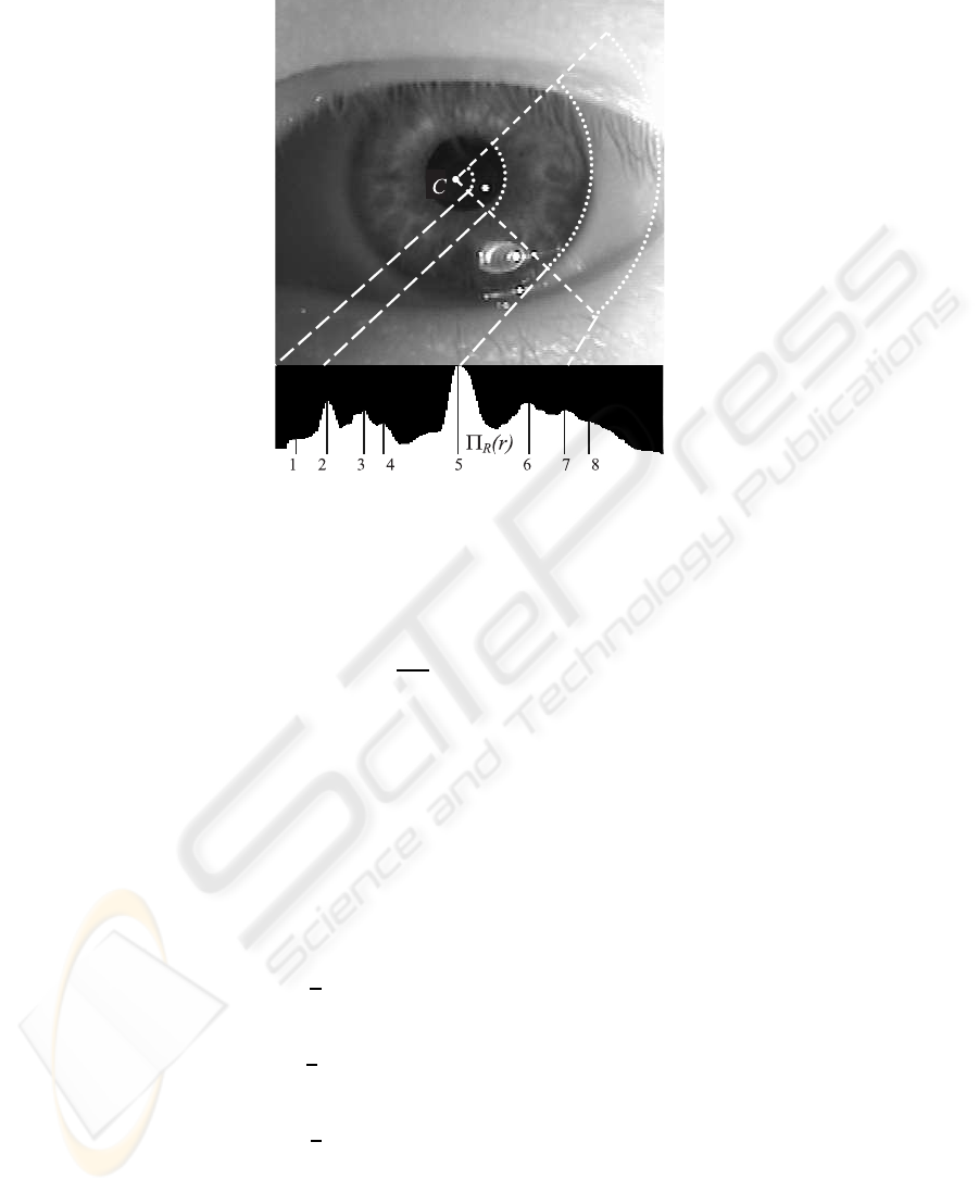
Fig.1. Sample of circular projection and local maxima positions.
Taking one of above conditions, for instance, U ≡ R for v
U
(x) one can obtain
a histogram of number of points satisfying the conditions as a function of radius. For
example the following is a histogram of right quadrant normalized to radius:
Π
R
(r) =
1
2πr
X
r−0.5<kxk<r+0.5
v
R
(x). (3)
The histogram may have several local maxima. Denote n-th local maxima value as
loc max
n,r
Π
R
(r) and its position as arg loc max
n,r
Π
R
(r).
Fig.1. represents eye image and its right quadrant histogram Π
R
(r). Eight local
maxima positions arg loc max
n,r
Π
R
(r), n = 1 . . . 8 are outlined in the histogram. After
detecting local maxima positions for all four quadrants one can obtain distances to
hypothetic circle borders from central point in appropriate direction.
Combining these values one can obtain coordinates of centers q = (q
x
q
y
)
T
and
radii ρ of these circles:
q
n,m
x
=
1
2
arg loc max
n,r
Π
R
(r) − arg loc max
m,r
Π
L
(r)
, (4)
q
u,v
y
=
1
2
arg loc max
u,r
Π
T
(r) − arg loc max
v,r
Π
B
(r)
, (5)
ρ
n,m,u,v
=
1
4
arg loc max
n,r
Π
R
(r) + arg loc max
m,r
Π
L
(r)+
arg loc max
u,r
Π
T
(r) + arg loc max
v,r
Π
B
(r)
. (6)
47

Quality of circle obtained for four given positions of local maxima (n, m, u , v) (in
right, left, top and bottom projections respectively) may be estimated as sum of projec-
tion function values in these positions:
Q
n,m,u,v
= loc max
n,r
Π
R
(r) + loc max
m,r
Π
L
(r) + loc max
u,r
Π
T
(r) + loc max
n,r
Π
B
(r). (7)
3 Selection of Interrelated Histogram Maxima
So, various hypothetic circles are constructed by a method of circular projections. The
circles can be hypothetic pupils (index P is used further) or irises (index I). Circles can
be defined by their parameters, center position and radius: (q
P
, r
P
) (q
I
, r
I
). If two
circles are the borders of an iris the following limitations due to human iris nature [13]
are necessarily true:
1) r
P
>
1
6
r
I
(iris radius cannot exceed pupil radius more than six times);
2) r
P
<
3
4
r
I
(pupil radius cannot be bigger than 75% of iris radius);
3) d < r
P
, d = kq
P
− q
I
k iris center lies inside pupil circle;
4) 2(r
I
− r
p
− d) > r
I
− r
P
+ d, or after reduction d <
r
I
− r
P
3
(lengths of
segments between pupil and iris borders cut by a line passing through pupil and iris
centers do not differ by more than two times).
From all pairs of circles satisfying (1–4) the one is selected with maximum sum of
quality values.
Thus algorithm in whole consists of three steps:
1. Calculation of local gradients in image. Each of two gradient components require
six memory reads, five additions, one subtraction, three bit shifts and one memory write,
that is totally 24 integer operations per one image point.
2. Building circular projections (histograms) for four quadrants selecting local max-
ima in histograms. This requires evaluating indicator function (1) in each point. Check-
ing condition kgk > T
1
requires two memory reads for obtaining g
x
and g
y
, two mul-
tiplications, one addition and one comparison operations, totally six integer operations.
Most of image points do not have enough brightness gradient to pass this check and
are not involved in the following calculations. Checking condition T
2
<
x·g
kxk kgk
is split
to checking x · g > 0 and (x · g)
2
> T
2
2
x
2
g
2
to avoid square root calculation. First
of these conditions takes six integer operations and rejects half of points. Second takes
additional four multiplications and one comparison. Summing to projection histogram
is a single memory write operation. Totally, processing of each image point in this step
takes from 6 to 18 integer operations, and the major share of points is processed in 6
operations.
3. Enumeration of circle combinations searching most likely (with biggest quality)
pair. The computational cost of this step depends on the number of local maxima se-
lected rather than on source image size. Typical number of local maxima is around ten,
and there could be dosens of thousands of combinations from four maxima positions,
48

however most of them do not pass the limitations (1)-(4). Only less than hundred hy-
potheses are sensible and require quality calculation and comparison. Hence the amount
of calculations in this step is negligible compared to the previous ones.
Totally, from 30 to 42 integer operations per one image pixel are required, and
majority of pixels are treated with 30 operations. Image of the typical size of 640 ∗480
pixels is processed in 10 million operarions.
4 Experiments
The following databases from public domain were used for performing experimental
study:
— UBIRIS (http://www.di.ubi.pt/∼hugomcp/doc/ubiris.pdf),1207 im-
ages
— CASIA Iris Image Database (http://www.sinobiometrics.com),16213im-
ages
— Iris Challenge Evaluation (http://iris.nist.gov/ice/), 2954 images
Size of these images is 640 ∗ 480 pixels, iris radii vary from 50 to 200 pixels.
Testing method. Eye images were reviewed by human expert who indicated pupil
and iris borders in each of them. These data were then considered as true and were used
for method verification. Then images were processed automatically. The approximate
eye center was detected by method [9] (this point rarely matches true pupil center or
true iris center, but is always close to them). With the help of method proposed here
pupil and iris were detected. Their parameters were compared with those indicated by
human operator. Table below gives numbers of rude errors (difference in any one of
center coordinates or radii exceeds 10 percents of iris radius) and moderate (difference
in any one of center coordinates or radii exceeds 5 percents of iris radius) errors. If
all parameter values differ from true one not more than by five pixels, detection is
considered correct.
Table 1. Results of algorithm for test databases.
Data base Image
count
Number of
moderate
errors in
pupil
detection
Number
of rude
errors in
pupil
detection
Number of
moderate
errors in
iris
detection
Number
of rude
errors in
iris
detection
UBIRIS 1201 296 3 31 1
CASIA 16213 2070 48 274 43
ICE 2954 116 17 18 5
Execution of the algorithm takes not more than 0.01 second in PC with P-IV 3GHz
CPU for an image of 640 ∗480 pixels. Main share of calculation time is taken by Sobel
gradient estimation.
Proposed method of iris location may be applied for preliminary determination of
pupil (with precision up to 5 pixels) and iris (with precision up to 10 pixels) positions
if a point lying inside pupil is known. Method is useful for real-time applications.
49

References
1. Maenpaa T. An Iterative Algorithm for Fast Iris Detection IWBRS 2005. Beijing, China:
Beijing Press, P. 127–134.
2. Lipinski B. Iris Recognition: Detecting the pupil. http://cnx.org/content/m12487/latest/
3. Daugman J. High confidence personal identification by rapid video analysis of iris texture
Proc. IEEE Internat. Carnahan conf. on security technology, 1992. P. 50–60.
4. Wildes R.P., Asmuth J.C., Green G.L. et al. A system for automated iris recognition Proc.
of the 2nd IEEE Workshop on Applications of Computer Vision. 1994. P. 121–128.
5. Duda R.O., Hart P.E. Use of the Hough transformation to detect lines and curves in pictures
Comm ACM. 1972. V. 15. P. 11–15.
6. Benn D.E., Nixon M.S., Carter J.N. Robust eye centre extraction using the Hough Transform
Proc. 1st Int. Conf. on Audio- and Video-Based Biometric Person Authentication, 1997
7. Kimme C., Ballard D., Sklansky J. Finding circles by an array of accumulators Comm.
ACM. 1975. V. 18. P. 120–122.
8. Davies E.R. A high speed algorithm for circular object location Pattern Recognition Letters.
1987. V. 6. P. 323–333.
9. Matveev I.A. Method of detection of circle with known internal point Transactions of
Institute of System Analysis of RAS on Dynamics of Heterogeneous Systems, 2007. V. 31(1)
P. 288–293 (in Russian).
10. A.A. Rad, K. Faez, Qaragozlou N. Fast Circle Detection Using Gradient Pair Vectors Proc.
VIIth Digital Image Computing: Techniques and Applications, Sun C., Talbot H., Ourselin
S. and Adriaansen T. (Eds.), 10-12 Dec. 2003, Sydney.
11. C. Sun, Pallottino S. Circular Shortest Path in Images Pattern Recognition, Vol. 36, No.3,
pp.709-719, March 2003.
12. T.-C.Chen, K.-L.Chung An Efficient Randomized Algorithm for Detecting Circles Com-
puter Vision and Image Understanding 83, 172–191 (2001).
13. G.P.Potebnya, G.S.Lisovenko, V.V.Krivenko Clinical and experimental iridology Kiev,
Naukova dumka, 1995 (in Russian)
14. L.Masek, P.Kovesi MATLAB Source Code for a Biometric Identification System Based on
Iris Patterns. The School of Computer Science and Software Engineering, The University of
Western Australia. 2003.
50
