
COMPOSITIONAL VERIFICATION OF BUSINESS PROCESSES
MODELLED WITH BPMN
Luis E. Mendoza Morales
1
, Manuel I. Capel Tu˜n´on
2
and Mar´ıa A. P´erez
1
1
Processes and Systems Department, Sim´on Bol´ıvar University, PO Box 89000, Caracas 1080-A, Venezuela
2
Software Engineering Department, University of Granada, Aynadamar Campus, 18071 Granada, Spain
Keywords:
Business process modelling, Model–checking, Task model, Compositional verification, Formal specification.
Abstract:
A specific check that is required to be performed as part of the Business Process Modelling (BPM) is on
whether the activities and tasks described by Business Processes (BPs) are sound and well–coordinated. In
this work we present how the Model–Checking verification technique for software can be integrated within
a Formal Compositional Verification Approach (FVCA) to allow the automatic verification of BPs modelled
with Business Process Modelling Notation (BPMN). The FVCA is based on a formal specification language
with composition constructs. A timed semantics of BPMN defined in terms of the Communicating Sequential
Processes + Time (CSP+T) extends untimed BPMN modelling entities with timing constrains in order to detail
the behavior of BPs during the execution of real scenarios that they represent. With our proposal we are able to
specify and to develop the Business Process Task Model (BPTM) of a target business system. In order to show
a practical use of our proposal, a BPTM of an instance of a BPM enterprise–project related to the Customer
Relationship Management (CRM) business is presented.
1 INTRODUCTION
The Business Process Modelling Notation (BPMN)
(OMG, 2009) has become the “de facto” standard
graphical notation for Business Process Modelling
(BPM). BPMN describes processes in terms of or-
der dependencies between subprocesses and atomic
tasks. In a short time, BPMN has been supported by a
variety of BPM tools (OMG, 2009), and several com-
panies start using it as their standard modeling tech-
nique. However, existing verification tools can not di-
rectly be applied to BPMN models. BPMN is a graph-
ical notation that differ from the formal languages re-
quired by most existing verification tools. Moreover,
most automatic verification techniques and tools op-
erate on models described by using formal modeling
languages (as Petri nets or Process Algebras), not of-
ten used in industry. Then, to automatically carry out
the verification of a BPMN model the use of formal
languages is required as well as to transform/interpret
original BP models into “as–equivalent–as–possible”
executable formalmodels (knows as Business Process
Task Model —BPTM). The idea of obtaining directly
an executable model (i.e., a BPTM) from a BP
conceptual
1
one (e.g., a BPMN model) led us to pro-
pose a software verification framework, called Formal
Compositional Verification Approach (FCVA), appli-
cable to the BPM domain. With FCVA, the correct-
ness of any BPTM can be model–checked to deter-
mine the satisfaction of temporal BP properties, i.e.,
if the tasks behaviour conforms to the communica-
tion protocols, temporal consistency between collab-
orative tasks, etc., and temporal BP rules, such as
task timeliness and performance. We propose the
construction of a BPTM (i.e., a executable model
of the BP) as a set of process terms following the
construction rules of the Communicating Sequential
Processes + Time (CSP+T) process calculus. Thus,
the behavioural aspects and temporal constraints of a
BPMN model are specified and verified in the corre-
sponding BPTM by using the CSP+T formal speci-
fication language, as we will show in the sequel by
the discussion of an instance of Customer Relation-
ship Management (CRM) business. However, due our
approach is mainly supported on CSP–based calculus
(i.e., the model checkers are based on refinement con-
1
A BP descriptive model based on qualitative assump-
tions about its elements, their interrelations, and BP bound-
aries.
113
E. Mendoza Morales L., I. Capel Tuñón M. and A. Pérez M. (2010).
COMPOSITIONAL VERIFICATION OF BUSINESS PROCESSES MODELLED WITH BPMN.
In Proceedings of the 12th International Conference on Enterprise Information Systems - Information Systems Analysis and Specification, pages
113-122
DOI: 10.5220/0002974101130122
Copyright
c
SciTePress

cept (Roscoe, 1997)), its major limitation is that it is
restricted to check security properties (Roscoe, 1997).
In the literature we can find different works that
address the verification and validation of BP modelled
with BPMN. There are formal methods for verifying
BPMN models based on the π calculus (Ma et al.,
2008) or Petri Nets (Aalst, 2002), tools which can de-
bug grammatical errors in BPMN models and trans-
forms diagrams into BPEL (OASIS, 2007), and tech-
niques providing consistency of BPs written in Busi-
ness Process Execution Language for Web Services
(BPEL4WS) (OASIS, 2007) with Model–Checking
(MC) (D´ıaz et al., 2005), among others. In (Mo-
rimoto, 2005) is presented a extended survey of re-
cently proposed verification techniques for verifying
BPMN models and compare them between each other
and with respect to motivations, methods, and logics.
Nevertheless, none of the cited works merge mod-
elling of BPs with the specification, design and ver-
ification of BPTMs, and thus takes full advantage of
the strengths of the process calculus. Differently from
other research, our work is aimed at giving a sys-
temic, integrated vision of specification, design and
verification tasks of BPs, by incorporating the use of
MC tools in the BPTM development cycle. In or-
der to attain this, we establish how to combine differ-
ent formalisms within the same semantic domain (i.e.,
Kripke Structures —KS), so we can use this kind of
tool to allow us obtaining the verification of the com-
plete BPTM associated to a specific BP model.
The remainder of this paper is structured as it
follows. In the next section we give a short theo-
retical background (Clocked Computation Tree Logic
—CCTL— and CSP+T) that supports our approach.
Then, we give a brief description of BPMN, as an
introduction to the time semantics which is subse-
quently proposed for some BPMN notational ele-
ments. Next, we describe the compositional verifica-
tion proposal in detail. Finally, we apply our proposal
to a BPM related to the CRM business. The last sec-
tion gives the conclusions and future work.
2 FORMAL BACKGROUND
2.1 CSP+T
CSP+T (
ˇ
Zic, 1994) is a real–time specification lan-
guage which extends Communicating Sequential Pro-
cesses (CSP) (Roscoe, 1997) to allow the description
of complex event timings, from within a single se-
quential process, of use in the behavioural specifica-
tion of concurrent systems. CSP+T is a superset of
CSP, as a major change to the latter, the traces of
events are now pairs denoted as t.e, where t is the
global absolute time at which event e is observed. The
operators, related with timing and enabling–intervals
included in CSP+T are: (a) the special process instan-
tiation event denoted ⋆ (star); (b) the time capture
operator (1) associated to the time stamp function
a
e
= s(e) that allows storing in a variable a (marker
variable) the occurrence time of an event e (marker
event) when it occurs; and (c) the event–enabling in-
terval I(T, t
1
).a, representing timed refinements of the
untimed system behaviour and facilitates the specifi-
cation and proof of temporal system properties (
ˇ
Zic,
1994). CSP–based MC tools take a process (rep-
resenting the system implementation), and automat-
ically check whether the process fulfils the system
specification. B¨uchi automata (Alur and Dill, 1994)
have emerged as formal models derived from Kripke
structures (KS) (Clarke et al., 2000) to allow the anal-
ysis and verification of system behaviour. A variant of
these are timed B
¨
uchi automata (TBA), see Figure 1,
which are able to describe the time at which events
happen on any system run and the temporal proper-
ties holding in the next possible set of system states.
{«}
v
«
=0
S
1
{e}
S
2
[v
«
,v
«
+T]
{}
S
0
[v
«
+1,v
«
+T]
∅
P = 0.⋆ → I(T, v
⋆
).e → P
′
where :
v
⋆
= s(⋆) = 0
{e} ≡ occur(e)
Figure 1: Kripke structure of a CSP+T process term.
2.2 CCTL
Clocked Computation Tree Logic (CCTL) (R¨uf and
Kropf, 1997) is a temporal logic extending CTL
(Clarke et al., 2000) with quantitative bounded tem-
poral operators. See (R¨uf and Kropf, 1997) for more
details. CCTL includes the CTL with the operators
until (U) and the operator next (X) and other derived
operators in LTL, such as R, B, C and S, useful to
facilitate RTS properties specification. In CTL all
“LTL-like” temporal operators are preceded by a run
quantifier (A universal, E existential) which deter-
mines whether the temporal operator must be inter-
preted over one run (existential quantification) or over
every run (universal quantification) starting in the ac-
tual configuration. CCTL is an interval logics that
allow us to carry out a logical reasoning at the level
of time intervals, instead of instants. Within our ap-
proach, the basic model for understanding concurrent
systems is the interval structure
2
. Temporal logic MC
2
A state transition system with labelled transitions, as-
suming that every interval structure has exactly one clock
for the measure of time (R¨uf and Kropf, 1997).
ICEIS 2010 - 12th International Conference on Enterprise Information Systems
114

takes a structure (representing the system property)
which is unwound into a model and a formula, and au-
tomatically checks if the structure (model) meets the
specification (formula). The fundamental structures
are timed KS (unit–delay, temporal) (Clarke et al.,
2000); i.e., the model checker determines whether
the KS is a model of the formula. Figure 2 shows a
graphical example (a B¨uchi automaton (Alur and Dill,
1994)) of the KS of a CCTL formula.
{ϕ,¬ψ}
S
1
{ψ}
S
2
[a+1,b]
{}
S
0
[a,b-1]
[a+1,b-1]
[a+2,b]
φ = ϕU
[a,b]
ψ
Figure 2: Kripke structure of a CCTL formula.
3 BPMN AND VERIFICATION
BPMN has emerged as an important open standard
graphic notation for modelling and drawing BPs. The
main goal of BPMN is to provide a notation that is
readily understandable by all business users. BPMN
specifies a single diagram, called Business Process
Diagram (BPD). To depict a BP flow, you simply
model the Events that occur to start the BP, the Ac-
tivities and Tasks carried out, and the outcome of the
BP flow. Business decisions and flow branching are
modelled using Gateways. A Gateway is similar to a
decision symbol in a flowchart. Furthermore, an Ac-
tivity in the flow can be a sub–processes, which can
be graphically shown by another BPD connected via a
hyperlink to a process symbol. If an Activity is not de-
composed into sub–processes, it is considered a Task.
The Tasks are the lowest–level parts of a BP, i.e., the
atomic parts of BPs. A Pool typically represents an
organization or business entity and a Lane typically
represents a department or a business worker within
that organization or other things like functions, ap-
plications, and systems. When the BPM is done the
Pools can be further partitioned into Lanes. Both
Pools and Lanes represent Business Process Partici-
pants (BPPs) (OMG, 2009), i.e., these business enti-
ties, included in the BP, which follow process flows
that perform Activities and Tasks. A BPD repre-
sents a scenario of a business model. A scenario
describes how the workflow of a particular BP is re-
alized, in terms of collaborating business entities or
objects (Kruchten, 2003), within the business model.
According to (Wong and Gibbons, 2008), the
BPMN specification does not yet have a formal be-
havioural semantics, commonly accepted, to attain
this is very important for carrying out the behavioural
specification and verification activities of critical BPs.
This is particularly important when specifying BP
collaboration, where task coordination depends on the
execution order and on the duration of the other one.
BPs analysts and designers need tools and method-
ological approaches that support critical BPs verifi-
cation, as part of BPM. BPs verification, mainly in
the early development cycle, can provoke to take cor-
rective actions in time and at low cost for business.
Moreover, validation of BPM results is extremely ex-
pensive and risky for the development process when
postponed until system deployment. In this sense, our
proposal will help analysts and designers working on
BPM to conduct temporal verification of critical BP
models before starting the software’s life cycle im-
plementation phase.
3.1 Improving the BPMN Semantics
Our proposal takes as its starting point the seman-
tics for the BPMN analysis entities given in (Wong
and Gibbons, 2008), combined with CSP+T opera-
tors; specifically, the time capture operator (1) and
the event–enabling interval I(T, t).a (or [t, t + T].a),
to specify the response times of some notational el-
ements of BPMN and to control their time span, ac-
cording to the maximum times at which every task
must execute to meet the temporal constraints speci-
fied in the BP. In this way, a more precise and com-
plete semantics is obtained for the local diagrams that
represent individual participants, as well as for the
global diagram that represents business collaboration,
required by the BP and depicted in the BPD.
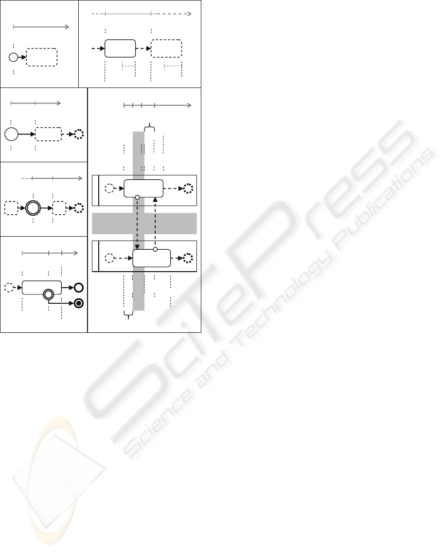
To briefly describe our proposal, the BPMN no-
tational elements specification is shown in Figure 3.
We define a direct map from the activities size (i.e.,
rounded rectangles) to the maximum (ran.max) and
minimum duration (ran.min), which are established
as part of the activities attributes. Furthermore, we
denote as t
x
the times at which the invocation events
ε
x
occur on the BPMN modelling entities, and with
Sx.ran.min and Sx.ran.max the minimum and maxi-
mum duration ranges of Sx activities, respectively, ac-
cording to what is established in BPMN.
In Figure 3 (a) the start event of BPMN is de-
picted, which represents the BP instantiation for its
execution. In CSP+T, its specification is performed
by means the ⋆ instantiation event and marking the
occurrence instant of that event in the v
⋆
marker vari-
able; i.e.,
P(start) =(⋆ 1 v
⋆
→ SKIP; P(start))2(ε
end
→ SKIP)
Let be the activity S1, which precedes the activ-
ity S2, according to the flow shown in Figure 3 (b).
According to the BPMN semantics which we pro-
pose, the start of the activity S2 execution (i.e., the
COMPOSITIONAL VERIFICATION OF BUSINESS PROCESSES MODELLED WITH BPMN
115
[v
S1
,S1.ran.min]
∩
.
[v
S2
,S2.ran.min]
[t
S1
,S1.ran.min]
∩
[t
S2
,S2.ran.min]
S1
¹
time
t
S1
t
exc
ε
S1
S1.ran.max
ε
exc
(e)
t
m1
t
m2
S1
S2
ε
S1
ε
S2
S2.ran.max
Pool 1
Pool 2
S1.ran.max
time
t
S1
t
S2
(f)
ε
m1
ε
m2
S2S1
¹
ε
itime
ε
S2
time
t
itime
t
S1
(d)
S1
¹
ε
S1
time
t
stime
t
S1
(c)
m1
m2
v
S1
v
itime
stime.ran
v
S2
max{t
S1
,t
S2
} = max
{
v
S1
,v
S2
}
v
S1
min
{
S1.ran.min, S1.ran.min
}
start
start.1
start.2
end
end
end
end.1
end.2
abort
t
end
S1.ran.min
S2.ran.min
itime.ran
etime.ran
(a)
S1
time
t
0
«
• • •
S1 S2
S1.ran.max
S1.ran.min
S2.ran.max
S2.ran.min
time
t
S1
ε
S1
t
S2
ε
S2
• • •
(b)
v
«
«
v
stime
start
Figure 3: Timing graphical analysis of some BPMN nota-
tional elements.
occurrence of event ε
S2
) depends on the ending in-
stant of activity S1, which must occur within the time
span of activity S2, given by the range S1.ran.min to
S1.ran.max. In its turn, the measurement of ranges
S1.ran.min and S1.ran.max depends on the occur-
rence of event ε
S1
. Then, we must make sure that the
event ε
S2
will timely occur; i.e., within the interval
[S1.ran.min, S1.ran.max] from the occurrence instant
t
S1
, stored in v
S1
, at which the S1 (ε
S1
) was invoked.
In CSP+T the process term that specifies the expected
behaviour is:
P(S1) =(ε
S1
1 v
S1
→ SKIP;
I(S1.ran.max− S1.ran.min,v
S1
+ S1.ran.min).ε
S2
→ SKIP; P(S1))
2(ε
end
→ SKIP)
The BPMN Timer Start and Timed Intermediate
events specify the delay in the BPMN modelling en-
tity invocation which precedes the Sequence Flow.
Then, according to the schema shown in Figure 3 (c)
and 3 (d), the process terms in CSP+T that specifies
those behaviours are:
P(stime) =(⋆ 1 v
stime
→ SKIP; I(stime.ran,v
stime
) → SKIP;
ε
S1
→ SKIP; P(stime))
2(ε
end
→ SKIP)
P(itime) =(ε
itime
1 v
itime
→ SKIP; I(T
itime
, v
itime
) → SKIP;
ε
S2
→ SKIP; P(itime))
2(ε
end
→ SKIP)
According to Figure 3 (e), the process term in
CSP+T specifying a task behaviour with an Exception
Flow, will present the following syntax:
P(S1) =(ε
S1
1 v
S1
→ SKIP;
I(S1.ran.max− S1.ran.min,v
S1
+ S1.ran.min).ε
end
→ (SKIP
a
I(S1.ran.max,v
S1
).ε
exc
→ SKIP;
abort.1 → STOP); P(S1))
2(ε
end
→ SKIP)
Finally, for the case of Message Flows, depicted
in Figure 3 (f), the process terms that include the col-
laboration between two participants Pool1 and Pool2,
are structured according to the following text:
P(S1) =(ε
S1
1 v
S1
→ SKIP;
I(min{S1.ran.min,S2.ran.min},max{v
S1
, v
S2
}).ε
m1
!x → SKIP;
I(min{S1.ran.min,S2.ran.min},max{v
S1
, v
S2
}).ε
m2
?y → SKIP;
I(S1.ran.max− S1.ran.min,v
S1
+ S1.ran.min).ε
end.1
→
→ SKIP; P(S1))
2(ε
end.1
→ SKIP)
P(S2) =(ε
S2
1 v
S2
→ SKIP;
I(min{S1.ran.min,S2.ran.min},max{v
S1
, v
S2
}).ε
m1
?x → SKIP;
I(min{S1.ran.min,S2.ran.min},max{v
S1
, v
S2
}).ε
m2
!y → SKIP;
I(S2.ran.max− S2.ran.min,v
S2
+ S2.ran.min).ε
end.2
→
→ SKIP; P(S2))
2(ε
end.2
→ SKIP)
4 BPTM VERIFICATION
APPROACH
The BP model can have several views and each view
is expressed through one or more diagrams (Eriksson
and Penker, 1998), which can be of several types, de-
pending on the situation or specific structure of the
business that needs to be portrayed. The diagrams
capture BP rules, goals, relations between objects and
their interactions. These views are not separated mod-
els, but different perspectives of one or more aspects
of the business being modelled. When together these
views create a complete business model (Eriksson and
Penker, 1998). In this work we focus only on the
BP view of a business model. According to BPMN
(OMG, 2009) and our objectives, we started from the
BPD because is the mechanism used by BPMN for
creating BP models, while at the same time BPD is
able to handle the complexity inherent to BPs (OMG,
2009). As we introduce previously, a BPTM structure
ICEIS 2010 - 12th International Conference on Enterprise Information Systems
116
is a set of groups of tasks, representing a large number
of possible real–world scenarios expressed in com-
pact form. Thus, we are focused here on the BPTM,
which allow us to obtain a description of most of the
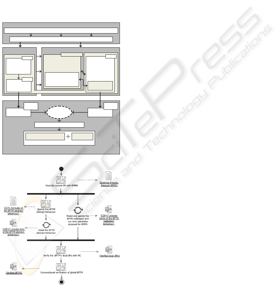
tasks that a BP accomplish (Patern`o, 2001). On Fig-
ure 4 we see the graphical summary of our proposal
that shows, (a) the integration of MC concepts with
our timed semantics proposal for BPMN and (b) the
workflow with the different paths to be followed in its
application and artifacts (denoted inside brackets) that
are obtained from the activities execution, to carry out
the verification of a BPTM.
BMTM MODELLINGBPTM BEHAVIOUR
SPECIFICATION
BUSINESS PROCESS MODELLING
THE BUSINESS PROCESS CORRECTNESS CAN BE ANALYSED BY BUSINESS
ANALYSTS AND DESIGNERS
Common semantics: Kripke structures
BPMN ELEMENTS
DESCRIPTION ACCOR-
DING TO CSP+T
SEMANTICS
FLOW OBJECTS
–
CONNECTING OBJECTS
–
SWIMLANES
BPTM BEHAVIOUR
OBTAINED AS A
PARALLEL
COMPOSITION OF
CSP+T
PROCESSES
SET OF CSP+T
PROCESS TERMS
BPMN -->CSP+T
CSP+T
TIMING
SPECIFICATION
ABSTRACTED
INFORMATION - EVENTS - RESOURCES - GOALS - ACTIVITIES - BUSINESS RULES
SET OF BPMN BUSINESS PROCESS DIAGRAMS
BPTM ABSTRACT BEHAVIOUR BPTM MODEL
BUSINESS RULES
AND GOALS,
AND TEMPORAL
CONSTRAINTS
CCTL
CSP+T
EXPECTED
BEHAVIOUR
PERFORMED
BEHAVIOUR
VERIFICATION OF LOCAL BPs
MODEL
CHECKING
TRACES –
FAILURES
COMPOSITIONAL VERIFICATION OF GLOBAL BP
COMPOSITION OPERATOR
OF PROCESS ALGEBRA
DEDUCTIVE
TECHNIQUES
TRACES –
FAILURES
(a) Integrated view.
(b) Activity diagram.
Figure 4: Our verification proposal.
A complete behavioural description of the BPTM
cannot be obtained by only using the syntactic in-
formation provided by BPD without considering dy-
namic behaviour and temporal constrains represented
by the BPMN notational elements (i.e., activities —
tasks and sub–processes—, and timer start and timer
intermediate events) and the timed constrains relate
to the participants collaboration (i.e., the message in-
terchange represented by message flows). As result
we obtain a set of detailed CSP+T process terms (i.e.,
the BPTM), which describes completely the tempo-
ral behaviour of the BP described by the BPD. We
can check the correctness of the BPTM by using a
MC tool w.r.t. previously specified properties for the
BPTM derived from the business rules and goals.
The complete description of the BPTM tempo-
ral behaviour is obtained by applying our timed
semantics proposal to some BPMN notational el-
ements. Thus, some non–functional requirements
(i.e., deadlock–freeness, reliability) and temporal
constrains (i.e., timeliness, deadlines) that the BPTM
must fulfill are specified in CCTL (see an example
of such a formula in Figure 2), which is based on
the interval structure and time–annotated automata
(R¨uf and Kropf, 1997). Afterwards, these proper-
ties are expressed by a set of CSP+T process terms
that represents the abstract expected behaviour of the
BPTM. As result, we obtain a set of detailed CSP+T
process terms that specify and deal with behavioural
aspects and temporal constrains of the BPMN nota-
tional elements involved into the BPTM realization.
In this sense, the verification carried out here exclu-
sively refers to the BPTM behaviour modelled by the
CSP+T process conformed by the set of CSP+T pro-
cess terms that describe the behaviour of the BPMN
elements, i.e., the composition of the CSP+T process
terms that represents the activities performed by the
participants collaboration.
Once obtained the BPTM model (i.e., the set of
CSP+T process term that represents the realization
of the BP), we can proceed to BPTM verification
according to the rules of CSP–based process calcu-
lus. By using CSP–based MC tools we model check
the local BPs corresponding to the Pools within the
BPD against the set of process process terms that rep-
resents the properties (i.e., the expected behaviour)
that the BPTM must be accomplish. Finally, by the
BPTM compositionalverification Theorem, we obtain
the complete verification of the BPTM behaviour that
corresponds to the global BP BPD, according to the
relation (1).
BPTM Compositional Verification. Let the global
BP BPD be structured into several business partici-
pants Pool
i
working in parallel, BPD =
f
i:1..n
Pool
i
.
COMPOSITIONAL VERIFICATION OF BUSINESS PROCESSES MODELLED WITH BPMN
117

For a set of process terms T(Pool
i
) describing the
behaviour of business participants Pool
i
, properties
φ
i
, invariants ψ
i
, and deadlock δ, with
T
i:1..n
Σ
i
= ∅,
T
i:1..n
Ω
i
= ∅, and
T
i:1..n
L (T(Pool
i
)) = ∅, the fol-
lowing condition holds
3
:
T(BPD) (φ∧ ψ∧ ¬δ) ⇔
n
i:1..n
T(Pool
i
)
^
i:1..n
(φ
i
∧ ψ
i
) ∧ ¬δ, (1)
where T(BPD) = k
i:1..n
T(Pool
i
).
Since our approach is aimed at representing
BPTM concurrent aspects, the contribution is more
focused on compositional verification of consistency
and synchronization of concurrent local BPs which
conform the BPTM than in other BPs oriented vali-
dations; i.e., according to our approach, the verifica-
tion of structured BPTM can be carried out with cor-
rectness by only starting from the verification of the
simplest BPMN local process.
As final remark, the main objective of this work
is aimed at verification of BPTM, which are derived
from a series of BPs modelled with BPMN. However,
our proposal can be adapted to other BPM languages
and standards which allow the transformation of the
properties to verify and the modelling elements of
BPTM into formal language constructs supported by
MC tools; i.e., KS. See (Capel et al., 2008) to review
an example of an adaptation of our BPTM verification
approach to a BPTM derived from BPs modelled with
BPM UML stereotypes.
5 AN APPLICATION OF FCVA
To show the applicability of our proposal, it was ap-
plied to a BPM enterprise–project related to the CRM
business (Mendoza et al., 2007). To perform the
verification of the BPTM associated with CRM BP
using our approach, the business requirement anal-
ysis and context should be obtained beforehand, by
means of a BPM. In summary, the BPM obtained the
Informing Customer, Customizing Service, Studying
Behaviour Pattern, Product/Service Produce, Prod-
uct/Service Sell and Assisting Customers BPs that rep-
resent a minimum functionality of the CRM strategy
and are key factors to understanding the CRM busi-
ness. We will only use the BPMN BPDs obtained
from the CRM BPM considered of interest to show
our verification approach.
We will only show an example of application of
the timed semantics proposed for BPMN and we only
focus on the verification of one CRM BP. We se-
lected to work with the Product/Service Sell BP, due
3
Σ
i
, Ω
i
, and L (T(Pool
i
)), represents the set of input and
output signals, and labelling, respectively, of the process
T(Pool
i
).
to its importance to the CRM strategy. The required
information to allow formal reasoning about CRM
participant collaboration is displayed by the Prod-
uct/Service Sell BPD shown in Figure 5, which al-
lows a Company performing the activities associated
with selling a Product/Service requested by a Cus-
tomer). We can see that the Customer is represented
by a Pool and the Company by other one, which ex-
change Message Flows to achieve the collaboration
required by the BP. In turn, the Company is par-
titioned in Lanes (i.e., Sales, a Logistic agent, and
Attention channel), representing the Company’s in-
ternal participants involved in the realization of the
BP. The Product/Service Sell BP starts when a Cus-
tomer requests a communication with the Company.
In this sense, the BP meets Customer requirements
to buy certain Product/Service. However, the Prod-
uct/Service Sell BP can be initiated by the Com-
pany to respond to CRM strategies to sell any Prod-
uct/Service to the Customers. As shown in Figure 5,
the BP provides a high collaboration from the par-
ticipants to achieve their execution, which deserves a
synchronization of the activities involved in message
flows.
5.1 BPTM Definition and Description
Known as Product/Service Sell BP modelled with
BPMN, now the next step is to obtain its specifica-
tion in CSP+T, according to the proposal briefly de-
scribed in section 3.1, which amounts to the definition
and semantic description of the BPMN modelling en-
tities that represent duration times
4
. We define the
sets CU, CO, and CO2 for indexing the processes
mapped to the modelling entities of Customer (i.e.,
Cus), Company (i.e., Com) participants, and the sub-
process co s2 (i.e., SubCom), respectively (see Fig-
ure 5), pointed out below:
CU = {start.1, cu s1, cu s2, cu s3, cu s4, cu s5, cu s6,
xgate.1, end.1, abort.1}
CO = {start.2, co s1, co s2, co s21, co s3, co s4, co s5,
co s6, co s7, co s8, agate.1, agate.2, end.2, abort.2}
CO2 ={start.3, co s21, end.3}
Cus =let X =2i : (αY\{fin.1, abt.1})•
(i → X2fin.1 → SKIP2abt.1 → STOP)
Y =(ki : CU • αP(i) ◦ P(i))
within(Y | [αY] | X)\{| init.Cus |}
Com =let Z =2j : (αR\{fin.2,abt.2})•
(j → Z2fin.2 → SKIP2abt.2 → STOP)
R =(kj : CO • αP(j) ◦ P(j))
within(R | [αR] | Z)\{| init.Com |}
4
Here, duration times are expressed in seconds, accord-
ing to the function sec defined in (Wong and Gibbons,
2008).
ICEIS 2010 - 12th International Conference on Enterprise Information Systems
118
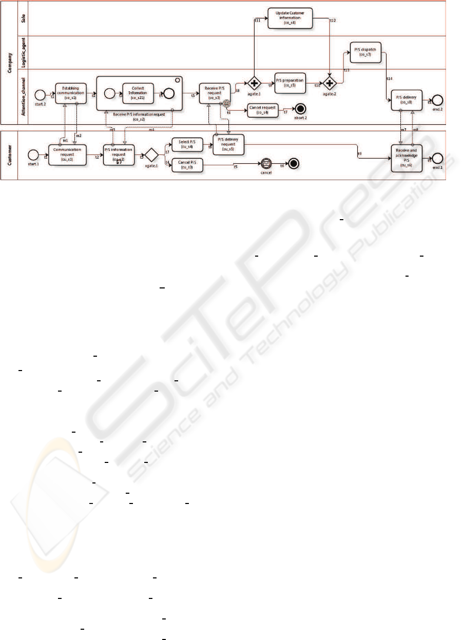
Figure 5: BPD of the Product/service Sell BP.
SubCom =let T =2k : (αW\{fin.3}) • (k → T2fin.3 → SKIP)
W =(kk : CO2• αP(k) ◦ P(k))
within(W | [αW] | T)\{| init |}
where for each i ∈ CU, j ∈ CO, and k ∈ CO2, the
processes P(i), P(j), and P(k), respectively, are de-
fined next. We use n ∈ N to denote the number of
Product/Service information request (cu s2) Activity
instances. We will only present some of the processes
that make up the Cus, Com, and SubCom due to space
limitations, to illustrate the application of the pro-
posed semantics.
P(start.1) =(t0.⋆ → init.Cus.cu s1 → SKIP)2fin.1 → SKIP
P(cu s2) =
let A(n) =n > 0 & (init.Cus.cu s2 → SKIP#starts.Cus.cu s2 → SKIP#
msg.cu s2!x : {in, last} → SKIP#msg.cu s2.out →
→ SKIP#
init.Cus.xgate.1 → SKIP#A(n− 1))2init.Cus.xgate.1
→→ SKIP
X(n) =(init.Cus.cu s2 → SKIP2init.Cus.xgate.1 → SKIP)#
(n > 1 & (init.Cus.cu s2 → (msg.cu s2.in → X(n− 1)
2msg.cu s2.last → init.Cus.xgate.1 → SKIP))
2 n = 1 & (init.Cus.cu s2 → msg.cu s2.last →
init.Cus.xgate.1 → SKIP)
2 n = N & msg.cu s2.end → init.Cus.xgate.1 → SKIP)
within((A(n) | [SynSet] | X(n)) #P(cu s2))2fin.1 → SKIP
SynSet = {msg.cu s2.in, msg.cu s2.last, init.Cus.cu s2,
init.Cus.xgate.1}
P(cancel) =(init.Cus.cancel → SKIP #msg.cancel!x : {can} → SKIP#
msg.cancel.out → SKIP#init.Cus.abort.1 → SKIP#
P(cancel))2fin.1 → SKIP
P(abort.1) =(init.Cus.abort.1 → SKIP#abt.1 → STOP)2fin.1 → SKIP
P(co s2) =(init.Com.co s2 1 vs2 → SKIP#msg.co s2!x : {in, last} →
→ SKIP#
msg.co s2.out → SKIP#starts.Com.co s2 → SKIP#
(SubCom | [{end.3}] | end.3 →
I(86400− 64800, vs2 + 64800).init.Com.co s3 → SKIP)
| [{init.Com.co s3}] |
I(86400− 64800, vs2 + 64800).init.Com.co s3 → SKIP)#
#P(co s2))
2fin.2 → SKIP
P(end.2) =init.Com.end.2 → SKIP#fin.2 → SKIP
P(co s21) =(init.Com.co s21 1 vs21 → SKIP#starts.Com.co s21 →
→ SKIP#
I(1800, vs21).init.Com.end.3 → SKIP#P(co s21))2fin.3 →
→ SKIP
Finally, the collaboration between the participants
Customer and Company is the parallel composition of
processes Cus and Com, as it is denoted by the process
term CSP+T PSS:
PSS = (Cus | [αCuskαCom] | Com)\{| msg |}
The set of processes previously described (Cus, Com,
and PSS), conform the BPTM of the Product/Service
Sell BP expressed in CSP+T. In this sense, this BPTM
is the one to be verified with respect to the specified
properties in CCTL that are presented in the next sec-
tion.
5.2 Properties Definition
In order to show the application of our proposal, we
will work with the following property, which is con-
nected with the obligation of receiving and obtaining
the Product/Service delivery confirmation, once the
Customer has initiated the communication with the
Company. As we will proceed with the verification
of the BPTM behaviour (previously denoted as PSS)
from the sub-processes that make it up (i.e., Cus and
Com), by applying our compositional verification ap-
proach, then we must define the properties that each
participant must fulfil, which show the execution se-
quence of BPMN notational elements expected when
they execute the partial processes of whom it is re-
sponsible. The participants must execute all their ac-
tivities as they are pointed out in the workflowin order
COMPOSITIONAL VERIFICATION OF BUSINESS PROCESSES MODELLED WITH BPMN
119

to achieve the functioning of the global process. The
partial properties, which we must verify in processes
Cus and Com, respectively, to obtain the verification
of process PSS, are defined below.
φ
Cus
=AG
[a,b]
(Start.1 → A[cu s1 U
[a+1,b−5]
(cu s2 ∧
A[cu s2 U
[a+2,b−4]
(xgate.1 ∧ A[xgate.1 U
[a+3,b−3]
(cu s4 ∧
A[cu s4 U
[a+4,b−2]
(cu s5 ∧ A[cu s5 U
[a+5,b−1]
(cu s6 ∧
A[cu s6 U
[a+6,b]
End.1])])])])])])
φ
Com
=AG
[a,b]
(Start.2 → A[co s1 U
[a+1,b−8]
(co s2 ∧
A[cu s2 U
[a+2,b−7]
(co s3 ∧ A[co s3 U
[a+3,b−6]
(agate.1 ∧
A[agate.1 U
[a+4,b−5]
({co s5 ∨ co s6} ∧
A[{co s5∨ co s6} U
[a+6,b−3]
(agate.2 ∧
A[agate.2 U
[a+7,b−2]
(co s7 ∧ A[co s7 U
[a+8,b−1]
(co s8 ∧
A[co s8 U
[a+9,b]
End.2])])])])])])])])
According to the CSP–based process calculus, the
expected behaviour must be expressed according to
the event sequence that should be observed as result
of BPTM run. In this sense, we then have to interpret
the prior property according to the expected sequence
of events that the Product/Service Sell BP must show
off in order to perform its verification. The opera-
tional interpretation CCTL formulas previouslyspeci-
fied, according to the process calculus CSP+T, are the
processes T(φ
Cus
) and T(φ
Com
) that are presented be-
low and describe the expected behaviour for the par-
ticipants that realize the BPTM.
T(φ
Cus
) = t
0
.⋆ → T(Start.1)
T(Start.1) = I((b− 6) − a, a).init.Cus.cu s1 →
→ T(cu s1)
T(cu s1) = I((b− 5) − (a + 1), a+ 1).init.Cus.cu s2 →
→ T(cu s2)
T(cu s2) = I((b− 4) − (a + 2), a+ 2).init.Cus.xgate.1 →
→ T(xgate.1))
T(xgate.1) = I((b− 3) − (a+ 3), a+ 3).init.Cus.cu s4 →
→ T(cu s4)
T(cu s4) = I((b− 2) − (a + 4), a+ 4).init.Cus.cu s5 →
→ T(cu s5)
T(cu s5) = I((b− 1) − (a + 5), a+ 5).init.Cus.cu s6 →
→ T(cu s6)
T(cu s6) = I(b− (a+ 6), a+ 6).init.Cus.end.1 → T(End.1)
T(End.1) = SKIP#T(φ
Cus
)
T(φ
Com
) = t
0
.⋆ → T(Start.2)
T(Start.2) = I((b− 9) − a, a).init.Com.co s1 → T(co s1)
T(co s1) = I((b− 8) − (a+ 1), a+ 1).init.Com.co s2 →
→ T(co s2)
T(co s2) = I((b− 7) − (a+ 2), a+ 2).init.Com.co s3 →
→ T(co s3))
T(co s3) = I((b− 6) − (a+ 3), a+ 3).init.Com.agate.1 →
→ T(agate.1)
T(agate.1) = (I((b− 5) − (a+ 4), a+ 4).init.Com.co s5 →
→ T(co s5)) 2
(I((b− 5) − (a+ 4), a+ 4).init.Com.co s6 →
→ T(co s6))
T(co s5) = (I((b− 4) − (a+ 5), a+ 5).init.Com.co s6 →
→ T(co s6)) 2
(I((b− 3) − (a+ 6), a+ 6).init.Com.agate.2 →
→ T(agate.2))
T(cu s6) = (I((b− 4) − (a+ 5), a+ 5).init.Com.co s5 → T(co s5)) 2
(I((b− 3)(a+ 6), a+ 6).init.Com.agate.2 → T(agate.2))
T(agate.2) =I((b− 2) − (a+ 7), a+ 7).init.Com.co s7 → T(co s7)
T(co s7) = I((b− 1) − (a+ 8), a+ 8).init.Com.co s8 → T(co s8)
T(co s8) = I((b) − (a+ 9), a+ 9).init.Com.end.2 → T(End.2)
T(End.2) = SKIP#T(φ
Com
)
5.3 Verifying the Collaboration
Once obtained the set of CSP+T process terms that
represent the BPTM as well the properties which it
has to fulfil, we start to perform the verification of the
BPTM. According to our approach, we must verify
that the processes representing the behaviour of the
participants in the BPTM (i.e., Cus and Com) fulfil the
properties specified in section 5.2. Then, according to
the semantic domain to which CSP calculus, it can
be checked that the following refining relations are
fulfilled:
T(φ
Cus
) ⊑
T
Cus , T(φ
Com
) ⊑
T
Com (2)
T(φ
Cus
) ⊑
F
Cus , T(φ
Com
) ⊑
F
Com (3)
To verify the above relationships, we are going to
work according to the semantic model of CSP without
temporal operators, since, as pointed out in (Schnei-
der, 2000), untimed safety and liveness properties of a
timed system should verifiable in the untimed model
and later should be used in the timed analysis. Fur-
thermore, this allows us to integrate the use of FDR2
tool to carry out the verification of processes that rep-
resent the participants. In the sequel we present the
process terms CSP UT(φ
Com
) and UT(φ
Cus
), which
correspond to the expected untimed behaviour of un-
timed processes UT(Com) and UT(Cus) (which are
not shown due to space limitations), respectively, of
Customer and Company participants:
UT(φ
Cus
) = ⋆ → UT(Start.1)
UT(Start.1) = init.Cus.cu s1 → UT(cu s1)
UT(cu s1) = init.Cus.cu s2 → UT(cu s2)
UT(cu s2) = init.Cus.xgate.1 → UT(xgate.1))
UT(xgate.1) =init.Cus.cu s4 → UT(cu s4)
UT(cu s4) = init.Cus.cu s5 → UT(cu s5)
UT(cu s5) = init.Cus.cu s6 → UT(cu s6)
UT(cu s6) = init.Cus.end.1 → UT(End.1)
UT(End.1) = SKIP #UT(φ
Cus
)
UT(φ
Com
) = ⋆ → UT(Start.2)
UT(Start.2) = init.Com.co s1 → UT(co s1)
UT(co s1) = init.Com.co s2 → UT(co s2)
UT(co s2) = init.Com.co s3 → UT(co s3))
UT(co s3) = init.Com.agate.1 → UT(agate.1)
UT(agate.1) =(init.Com.co s5 → UT(co s5)) 2
(init.Com.co s6 → UT(co s6))
UT(co s5) = (init.Com.co s6 → UT(co s6)) 2
(init.Com.agate.2 → UT(agate.2))
UT(cu s6) = (init.Com.co s5 → UT(co s5)) 2
init.Com.agate.2 → UT(agate.2))
ICEIS 2010 - 12th International Conference on Enterprise Information Systems
120

UT(agate.2) =init.Com.co s7 → UT(co s7)
UT(co s7) = init.Com.co s8 → UT(co s8)
UT(co s8) = init.Com.end.2 → UT(End.2)
UT(End.2) = SKIP#UT(φ
Com
)
According to the timewise refinement concept
(Schneider, 2000), the description of an untimed pro-
cess sets constraints on the ordering and ultimate
availability of events, and allows all timed behaviours
that are consistent with its description. In this sense,
we can write the following relations:
T(φ
Cus
) ⊑
T
Cus ⇒ UT(φ
Cus
) ⊑
T
UT(Cus), (4)
T(φ
Com
) ⊑
T
Com ⇒ UT(φ
Com
) ⊑
T
UT(Com), (5)
T(φ
Cus
) ⊑
F
Cus ⇒ UT(φ
Cus
) ⊑
F
UT(Cus), (6)
T(φ
Com
) ⊑
F
Com ⇒ UT(φ
Com
) ⊑
F
UT(Com), (7)
which establish that the verification of untimed terms
in CSP is a necessary condition for the verification
of timing CSP+T terms. This allows us to check the
timed component behaviour on the basis of the se-
quence events admitted by the untimed CSP model,
excluding from analysis the events sequence that may
not correspond with the correct order of events, re-
sulting from the aggregation of the timing constraints
of timed CSP+T model. This will minimize the state
explosion problem because MC tools works over an
untimed model of the system that is smaller, and cor-
responds directly with the correct event sequence ex-
ecution of the timed model.
Thus, the behaviour of the participants Customer
and Company specified in CSP are verified w.r.t. the
semantic domains of traces and failures, which en-
sures that safety and liveness properties are satisfied,
respectively. Then, we can obtain that the behaviour
of the Cus and Com process terms are correct, i.e.,
all timed behaviour of CSP+T process terms are con-
sistent with its description. In other words, the time-
wise refinement of CSP+T process terms is consistent
with the untimed description of CSP process terms,
and these impose further constraints upon the timed
behaviour of CSP+T process terms. Thus, the rela-
tions (2) and (3) are true.
Consequently, we consider that the behaviour ver-
ification of constituent participants of the BPTM
should be performed using the FDR2 MC tool, since
we are working with an algebra based on CSP, such
as CSP+T. As can be observed in the FDR2 screen-
shot in Figure 6, the verification of local BP of
each participant untimed model in CSP, COMPANY
(i.e., UT(Com)) and CUSTOMER (i.e., UT(Cus)),
of the BPTM for Product/Service Sell BP satisfies
the untimed expected behaviour of each, COMP (i.e.,
UT(φ
Com
)) and CUST (i.e., UT(φ
Cus
)), respectively
(see check marks at rows one and two, respectively).
Figure 6: FDR2 screenshot.
According to relation (1) (see section 4), to prove
the correctness of the BPTM of the Product/Service
Sell BP w.r.t. its expected behaviour, it must be
demonstrated that:
PSS φ
PSS
⇔ (Cus | [αCuskαCom] | Com)\{| msg |} φ
Cus
∧ φ
Com
.
We have verified with FDR2 that:
Cus |= φ
Cus
and Com |= φ
Com
.
Based on the detailed design of Cus and Com local
BP shown in Figure 5, we must determine whether
these local BPs are “composable”. Thus, we must
verify that it fulfills the following 2 conditions:
1. The input signals (Σ
Cus
and Σ
Com
) and the output
signals (Ω
Cus
y Ω
Com
) of both local BP are dis-
jointed, which can be seen below:
Σ
Cus
∩ Σ
Com
= ∅ (8)
Σ
Cus
= {msg.cu s1.out, msg.cu s2.out, msg.cancel.out,
msg.cu s5.out, msg.cu s6.out}
Σ
Com
= {msg.co s1.out, msg.co s2.out, msg.co s3.out,
msg.co s3.can, msg.co s8.out}
Ω
Cus
∩ ΩCom = ∅ (9)
Ω
Cus
= {msg.cu s1.in, msg.cu s1.last, msg.cu s2.in,
msg.cu s2.last, msg.cancel.can, msg.cu s5.in,
msg.cu s5.last, msg.cu s6.in, msg.cu s6.last}
Ω
Com
= {msg.co s1.in, msg.co s1.last, msg.co s2.in,
msg.co s2.last, msg.co s3.in, msg.co s3.last, }
msg.co s8.in, msg.co s8.lastmsg.co s8.last}
2. The labelling sets of both components, L (Cus)
and L (Com), are disjointed, which can also be
verified as follows:
L (Cus) ∩ L (Com) = ∅ (10)
L (Cus) = {start.1, cu s1, cu s2, cu s3, cu s4, cu s5, cu s6,
xgate.1, end.1, abort.1}
L (Com) = {start.2, co s1, co s2, co s21, co s3, co s4, co s5,
co s6, co s7, co s8, agate.1, agate.2, end.2, abort.2}
Having verified that the relations (8), (9), and (10),
are true, we conclude that Cus and Com are “com-
posable”. By the BPTM compositional verification
theorem (see section 4), we have:
(Cus | [αCuskαCom] | Com)\{| msg |} |= φ
Cus
∧ φ
Com
COMPOSITIONAL VERIFICATION OF BUSINESS PROCESSES MODELLED WITH BPMN
121

and because
PSS = (Cus | [αCuskαCom] | Com)\{| msg |} and φ
PSS
= φ
Cus
∧ φ
Com
,
we obtain PSS |= φ
PSS
.
Finally, we have obtained the verification of a
BPTM corresponding to the Product/Service Sell BP
from their verified local BP, Customer and Company.
Therefore, we can claim that our approach has been
successfully applied to an instance of CRM business.
Finally, we can affirm that our approach may be a
means to precise the semantic of BPMN and to per-
form the verification of complex global BP modelled
with BPMN from collections of its verified local BPs.
6 CONCLUSIONS
In this paper we have presented FCVA for composi-
tional global BP verification from independently veri-
fied local BPs performed by the bp participants. Also
is proposed to complement the FVCA with a timed
semantics of BPMN defined in terms of CSP+T for-
mal specification language, which extends the BPMN
elements with timing constrains in order to detail the
behaviour that they represent. We have shown the
value and practicality of our approach by means of
the application to a real–life BP in the field of CRM,
which has to meet timed collaboration requirements.
The CSP+T specification of the BPTM at the de-
sign phase can be verified against the CCTL speci-
fication of the BP properties. As a consequence, the
complete BPTM developed from its core participants
can also be proved correct by means of the formal
language CSP+T that allows local verification results
of CSP+T syntactical terms —representing individual
local BPs— to be exported into the entire global BP
verification, which is obtained as a concurrent com-
position of process terms.
Future and ongoing work will focus on the appli-
cation of FCVA and the timed semantics of BPMN to
other BPs verification; our goal is to conduct in–depth
research on verification of these specifications, and to
obtain tool supporting BPM by using state–of–the–art
verification tools.
REFERENCES
Aalst, W. (2002). Making Work Flow: On the Applica-
tion of Petri Nets to Business Process Management,
LNCS 2360: Application and Theory of Petri Nets
2002, pages 1–22. Springer–Verlag, Berlin.
Alur, R. and Dill, D. (1994). A theory of timed automata.
Theoretical Computer Science, 126(2):183–235.
Capel, M., Mendoza, L., and Benghazi, K. (2008). Auto-
matic verification of business process integrity. Int. J.
Simulation and Process Modelling, 4(3/4):167–182.
Clarke, E., Grumberg, O., and Peled, D. (2000). Model
Checking. MIT. The MIT Press, Cambridge, USA.
D´ıaz, G., Pardo, J.-J., Cambronero, M.-E., Valero, V.,
and Cuartero, F. (2005). Automatic Translation of
WS–CDL Choreographies to Timed Automata, LNCS
3670: Formal Techniques for Computer Systems and
Business Processes, pages 230–242. Springer–Verlag,
Berlin.
Eriksson, H.-E. and Penker, M. (1998). Business Modeling
With UML: Business Patterns at Work. John Wiley &
Sons, Inc., New York, USA.
Kruchten, P. (2003). The Rational Unified Process: An In-
troduction, Second Edition. Addison-Wesley Long-
man Publishing Co., Inc., Boston, USA, 3rd edition.
Ma, S., Zhang, L., and He, J. (2008). Towards formaliza-
tion and verification of unified business process model
based on pi calculus. Proc. ACIS International Con-
ference on Software Engineering Research, Manage-
ment and Applications, 1:93–101.
Mendoza, L., Marius, A., P´erez, M., and Grim´an, A. (2007).
Critical success factors for a customer relationship
management strategy. Inf. Softw. Technol., 49(8):913–
945.
Morimoto, S. (2005). A Survey of Formal Verification
for Business Process Modeling, LNCS 5102: Proc.
8th International Conference on Computational Sci-
ence (ICCS 2008), pages 514–522. Springer–Verlag,
Berlin.
OASIS (2007). Web Services Business Process Execution
Language Version 2.0. OASIS Open, Billerica, USA.
OMG (2009). Business Process Modeling Notation – ver-
sion 1.2. Object Management Group, Massachusetts,
USA.
Patern`o, F. (2001). Handbook of Software Engineering And
Knowledge Engineering: Recent Advances, chapter
Task Models in Interactive Software Systems. World
Scientific Publishing Co., Inc., River Edge, USA.
Roscoe, A. (1997). The Theory and Practice of Concur-
rency. Prentice–Hall International Ltd., Hertfordshire
UK.
R¨uf, J. and Kropf, T. (1997). Symbolic model checking for
a discrete clocked temporal logic with intervals. In
Proceedings of the IFIP WG 10.5 International Con-
ference on Correct Hardware Design and Verification
Methods, pages 146–163, London, UK. Chapman &
Hall, Ltd.
Schneider, S. (2000). Concurrent and Real–Time Systems –
The CSP Approach. John Wiley & Sons, Ltd., Chich-
ester, England.
ˇ
Zic, J. (1994). Time–constrained buffer specifications in
CSP+T and Timed CSP. ACM Transaction on Pro-
gramming Languages and Systems, 16(6):1661–1674.
Wong, P. and Gibbons, J. (2008). A Process Semantics for
BPMN, LNCS 5256: Proc. 10th International Confer-
ence on Formal Engineering Methods (ICFEM 2008),
pages 355–374. Springer–Verlag, Berlin.
ICEIS 2010 - 12th International Conference on Enterprise Information Systems
122
