
COMPATIBILITY VERIFICATION OF COMPONENTS IN TERMS
OF FUNCTIONAL AND EXTRA-FUNCTIONAL PROPERTIES
∗
Tool Support
Kamil Je
ˇ
zek and P
ˇ
remek Brada
Department of Computer Science and Engineering, University of West Bohemia, Pilsen, Czech Republic
Keywords:
Components, Component-based, Functional, Extra-functional, Non-functional, Compatibility verification,
Components interchangeability.
Abstract:
Component-based programming, as a technology increasing development speed and decreasing cost of the
final product, promises a noticeable improvement in a process of development of large enterprise applications.
Even though component-based programming is a promising technology it still has not reached its maturity.
The main problem addressed in this paper are compatibility checks of components in terms of functional
and extra-functional properties and their insufficient tool support. This paper summarizes a mechanism of
component compatibility checks and introduces a tool whose aim is to fill this gap mainly with respect to
the phase of testing the assembly of components. The introduced mechanism and the tool allow to check
component bindings before deployment into the target environment. It displays a component graph, details of
components and highlights incompatibility problems. Hence, the tool validates the presented mechanism and
provides useful support for developers when deciding which component to use.
1 INTRODUCTION
Nowadays, the need for an exchange of information
leads to the development of enterprise applications.
The complex enterprise applications are often de-
veloped from scratch, which is ineffective. Since a lot
of applications use the same parts, it is effective to use
pre-existing components.
Component-based programming is reaching its
maturity. A variety of industrial component frame-
works such as OSGi (OSGi, nd), Spring (Spring, nd),
Spring DM (Spring DM, nd) or EJB (EJB, 2006) ex-
ist. They are widely used and are supported by devel-
oper tools. Although a development process consists
of several phases, including creation and publication
of components, assembly of component systems, de-
ployment etc., the existing tools typically do not cover
all phases.
Software companies are starting to use these in-
dustrial frameworks, however many companies still
develop components only for internal usage. A world
component market has not evolved yet.
∗
This work was supported by the Grant Agency of the
Czech Republic under grant number 201/08/0266 “Meth-
ods and models for consistency verification of advanced
component-based applications”.
1.1 Goal of the Paper
This paper addresses an inadequate means of a tool
support to provide a sufficient verification of compo-
nents. This text first summarises a possible mecha-
nism of verifying components compatibility. How-
ever the main goal of the paper is to introduce a tool
that performs compatibility evaluation based on the
presented mechanism. The tool aims at covering the
phase of components assembly when the component
system is tested.
2 PROBLEM DEFINITION
Component-based programming still has some limi-
tations. A considerable limitation is the trust a devel-
oper has upon a component: once a developer gains a
component from a vendor he has only a limited possi-
bility to verify whether the vendor provides a compo-
nent with compatible interfaces. Obviously, any kind
of verification whether an assembly of the new com-
ponents is correct, increases reliability.
The basic life-cycle of the components in
component-based development consists of several
510
Ježek K. and Brada P. (2010).
COMPATIBILITY VERIFICATION OF COMPONENTS IN TERMS OF FUNCTIONAL AND EXTRA-FUNCTIONAL PROPERTIES - Tool Support.
In Proceedings of the 12th International Conference on Enterprise Information Systems - Information Systems Analysis and Specification, pages
510-514
DOI: 10.5220/0002974505100514
Copyright
c
SciTePress

Figure 1: Tool position in component life-cycle.
phases shown in Figure 1: The vendor publishes the
component on the market. The system architect ob-
tains a component from the supplier and assembles
the system. Before its deployment, he must test the
component in a test environment. Only if the system
as a whole works, it may be released (deployed) to
customers. Although this idea is a fundamental one,
it is barely followed in practise. The partial reason is
that commercial companies have no strong tools sup-
porting each phase.
Industrial component frameworks are often sup-
ported by tools, but the tools typically cover only the
development phase (by developers tools) and the run-
time phase (by component framework). On one hand
companies have resources to implement missing tools
and benefit from them. On the other hand they would
unlikely do it in a current state of research because an
instant profit is unsure.
This paper aims at filling the gap of a missing
tool covering the phase of test assembly with respect
to interface compatibility. The tool aims at help-
ing the developers in everyday work. Consequently,
it should lead to a better adoption of component-
based development. The rationale is that the develop-
ers may easily verify component assemblies without
time-consuming repeated run of the whole application
in the framework. Because one system may be com-
posed from a considerable amount of different com-
ponents, the reduction of testing time would lead to
noticably increased development speed.
3 COMPATIBILITY CHECKS
This section first shows a brief overview of our exper-
imental framework that serves as a prototype imple-
mentation. Then the verification mechanism, which is
used by the framework and implemented in the tool,
is summarised.
3.1 CoSi Framework
For experimental purposes, we have developed a com-
ponent framework called CoSi (Brada, 2008).
CoSi is implemented in Java and its component is
a jar file. The jar contains an extended manifest file
holding interface information. The manifest contains
information which allow compatibility checks.
Each component in CoSi is capable of providing
or requiring services or packages, may set or read at-
tributes, or may send or receive messages. The gen-
eral term for these capabilities is provided/required
features.
3.2 Components Matching
Every time a component is to be replaced by another
one the verification is run to check whether the new
component will not break the rest of the system.
There are many comparing mechanisms for com-
ponents. They range from behaviour conformance
(Beyer et al., 2007; Hn
ˇ
etynka and Pl
´
a
ˇ
sil, 2006), type-
based consistency (Zaremski and Wing, 1995; Fab-
resse et al., 2008) to EFPs (Becker et al., 2009; Mo-
hammad and Alagar, 2008). Here, we summarize a
mechanism used for CoSi and our tool. It combines
type-based and EFPs consistency.
In relation to all the features, the verification must
check compatibility in these steps:
1. features are bound by their names;
2. features with the same names match.
Each step must be performed separately for func-
tional and extra-functional properties.
Feature Binding. Functional Properties. The first
step for functional properties checks (1) that no fea-
ture (e.g. a service, an attribute) is missing on the
provided side – because another component may use
it – and (2) that no feature is added on the required
side – because no one would fulfil its need.
Extra-functional Properties. The first step checks
whether no property is missing on the provided side
and no property is added on the required side. The
principle is the same as for functional properties.
Properties Matching. The feature matching is dif-
ferent for functional and extra-functional properties.
For the functional ones it compares versions attached
to the features. The provided side of a new com-
ponent must offer a feature with an equal or greater
version (assuming that new versions keep a backward
compatibility) and a required feature must require an
equal or a lower version than the old feature.
COMPATIBILITY VERIFICATION OF COMPONENTS IN TERMS OF FUNCTIONAL AND EXTRA-FUNCTIONAL
PROPERTIES - Tool Support
511

If backward compatibility of versions is not guar-
anteed or a versioning is fallible, a more comprehen-
sive algorithms should be performed. For instance,
(Brada and Valenta, 2006) introduced a model deriv-
ing a compatibility decision by introspection of byte-
code of Java classes. The current CoSi implementa-
tion relies on the versioning approach.
Matching of extra-functional properties will be
explained in Section 4.
The two components may be marked as compati-
ble ones when steps 1-2 apply for services, packages,
events and attributes in respects with desired function.
Additionally, the steps 1-2 must also hold for extra-
functional properties for all services and the whole
component.
4 EXTRA-FUNCTIONAL
PROPERTIES MATCHING
We developed a mechanism (Jezek et al., 2010) which
stores extra-functional properties in a common repos-
itory.
In the paper (Jezek et al., 2010) we have intro-
duced the function γ : x × y → z;z ∈ {−1,0,1,“n/d”}
attached to each property. It compares two instances
x,y of the property type. The resulting value states
which of the two values is better (in terms of quality).
The meaning of the return values is: −1 ⇒ x is
worse than y; 0 ⇒ x is equal to y; +1 ⇒ x is better
than y; “n/d” ⇒ not-defined.
When two features with the same names are com-
pared, the function γ is computed. The comparison of
two components C
1
and C
2
then results in a sequence
(z
k
) where 1..k denotes each pair of the provided and
required feature which are matched by the name. The
two components then match only when z
prov
k
∈ {0,1}
for provided properties and z
req
k
∈ {−1,0} for re-
quired ones.
5 TOOL SUPPORT
The previous sections explained an approach to com-
paring components with one another in terms of their
interface compatibility. This section introduces a tool
that has been developed to implement the comparing
mechanism.
5.1 Components Graph Viewer
The tool supporting compatibility checks we have
been developing is called Component Graph Viewer
(CGV). This section describes the key concepts and
features of the tool.
5.1.1 Compatibility Checking
The main contribution of the CGV is that it serves as a
tool allowing a user to check a chain of implemented
components before they are deployed into a real sys-
tem. The user may check connections and features of
components and estimate whether they are suitable to
the real system. It verifies a system as an assembly
of components rather than checking each component
separately. It is an important aspect of the tool, be-
cause a component tested by its vendor does not have
to work as a part of a complicated system. The tool
provides assurance to the deployer that no connection
between component interfaces is broken.
Figure 2: Components Dependency.
The goal of the tool is to perform checks ad-
dressed in previous Sections 3.2 and 4.
The binding results are expressed by arches con-
necting two components. Currently the tool matches
names and versions of the features. Each component
which poses any problem in the matching process is
highlighted. Basically, it hints where a comparison
mechanism did not find any matching required fea-
ture. The example bar with the ”Service C“ that has
not been matched is shown in Figure 3.
Figure 3: Missing service.
5.1.2 Visual Representation and Usage
The tool is designed to provide the look correspond-
ing to the UML2 components diagram. The overview
of the components graph generated by the tool is
shown in Figure 2.
ICEIS 2010 - 12th International Conference on Enterprise Information Systems
512
The CGV allows to show a set of components
which are displayed as boxes and dependencies ex-
pressed by arches. The user may switch the type of
dependency be shown in terms of services, attributes,
packages and events. Every time the user changes the
dependency, the tool re-draws the arches to express
the desired dependency. This way the user may obtain
a brief overview of the system composed from com-
ponents and may estimate which changes will happen
in the system if a component is withdrawn or inter-
changed to another one.
The tool is naturally targeted to be used by hu-
mans and thus provides clear visual means to high-
light dependencies of components. Once a compo-
nent is selected, it re-colours the connected compo-
nents and changes the arches expressing connections
to bold ones. Labels showing the names of features
are dynamically re-drawn for a selected component.
It helps a user not to be confused with a lot of arches
and labels.
The user may select a single component and check
a properties bar with summarized information about
the component.
5.1.3 Design Features
The CGV has been developed on the Eclipse Rich
Client Platform (RCP)
2
and it displays components
using ZEST
3
framework. The RCP provides a rich
base for graphical user interfaces that made the im-
plementation of CGV easier. Before selecting ZEST,
we also considered GMF
4
and GEF
5
.
GMF in combination with EMF
6
allows to model
and generate the application. Despite its comprehen-
siveness, we found it too complicated for implement-
ing the simple graph. The other framework, GEF
is a fundamental graphical framework for RCP with
a wide spectrum of features. It allows to customise
graphical objects, but each feature must be tediously
coded. Finally, we have decided on ZEST which has
only limited possibility of customising the graphical
objects, but it supports easy implementation of fea-
tures such as an automatic layout, zoom, user interac-
tion etc.
The CGV reads information about components via
a Component Loader (CL) which is another tool that
is being developed by our research group. The CL
loads a representation of components and provides
2
www.eclipse.org/rcp/
3
www.eclipse.org/gef/zest/
4
www.eclipse.org/gmf/
5
www.eclipse.org/gef/
6
www.eclipse.org/emf/
them in the form of so called Bundle Types (BTs).
The abstraction mechanism is shown in Figure 4.
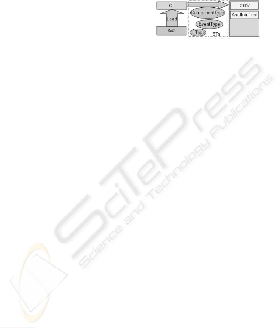
Figure 4: Component Loader.
Bundle Types are Java classes expressing meta-
informations about components. CL loads each com-
ponent and returns concrete Bundle Types, and the
view layer of the CGV then presents one bundle-type
instance as one element. This architecture allows the
CGV to use only meta-information provided by Bun-
dle Types rather than working directly with compo-
nents. CGV is then not tied with a concrete imple-
mentation of the component framework and may eas-
ily load components for other implementations. In ad-
dition, the representation of components may be eas-
ily provided to any other tool.
6 RELATED WORK
The behaviour of the system is addressed in (Beyer
et al., 2007). It generates the detailed specification
from the implementation and uses a refinement on
the level of behaviour specification. Another com-
ponent model, Palladio (Becker et al., 2009), gener-
ates the specification from the models of the system.
The main obstacle is the computational complexity
and the need of considerable amount of complicated
models.
Type-based approaches have relatively low cost
and high ease of use. The work (Brada and Va-
lenta, 2006) introduces a sub-typing framework that
reflects real changes in interfaces. The other solution
(Bauml and Brada, 2009) uses Java reflection to check
changes is interfaces. It results in a compatibility de-
cision. We would like to extend CoSi by the modified
comparator in the future. Other approaches, in ad-
dition, cover extra-functional properties (Jezek et al.,
2010; Mohammad and Alagar, 2008).
Components may be graphically represented by
standardised OMG’s UML diagrams (OMG, nd).
Mainly UML2 components diagram. Other ap-
proaches like OMG’s QoS UML profile (OMG, 2008)
or CQML’s profile (Aagedal, 2001) allows to explic-
itly model EFPs. Our tool corresponds closely with
the UML2 components diagram.
COMPATIBILITY VERIFICATION OF COMPONENTS IN TERMS OF FUNCTIONAL AND EXTRA-FUNCTIONAL
PROPERTIES - Tool Support
513

7 CONCLUSIONS AND FUTURE
WORK
This paper has highlighted one of the insufficiently
explored areas of component-based programming –
the tool support covering the development process of
component based development. The problem of vi-
sual checking of components connected in a testing
environment has been explicitly targeted.
The main contribution of this paper is a tool pro-
viding a visual component interchangeability verifi-
cation. Our expectation is that such a tool could
help a world wide component market to evolve. We
have overviewed a possible mechanism allowing to
compare two components by matching provided and
required features, and defined a components inter-
changeability checks.
The tool has been successfully tested for a set
of components, however it still needs improvements.
Firstly, we want to finish the matching to respect EFPs
and real changes in interfaces. Secondly, we would
like to implement the component loader for other
component frameworks. Then the tool will achieve
the overall goal – practical usage by developers.
ACKNOWLEDGEMENTS
We would like to thank our colleagues J. Kr
´
akora and
J. Ku
ˇ
cera who took careful effort in coding the pre-
sented graphical tool and the components loader re-
spectively.
REFERENCES
Aagedal, J. Ø. (2001). Quality of Service Support in Devel-
opment of Distributed Systems. PhD thesis, University
of Oslo.
Bauml, J. and Brada, P. (2009). Automated versioning in
OSGi: A mechanism for component software consis-
tency guarantee. In EUROMICRO-SEAA, pages 428–
435.
Becker, S., Koziolek, H., and Reussner, R. (2009). The pal-
ladio component model for model-driven performance
prediction. Journal of Systems and Software, 82(1):3
– 22. Special Issue: Software Performance - Modeling
and Analysis.
Beyer, D., Henzinger, T., and Singh, V. (2007). Algorithms
for Interface Synthesis. In CAV 2007, LNCS, pages
4–19. Springer.
Brada, P. (2008). The CoSi component model: Reviving
the black-box nature of components. In Proceedings
of the 11th International Symposium on Component
Based Software Engineering, number 5282 in LNCS,
Karlsruhe, Germany. Springer Verlag.
Brada, P. and Valenta, L. (2006). Practical verification of
component substitutability using subtype relation. In
Proceedings of the 32nd Euromicro SEAA conference,
pages 38–45. IEEE Computer Society.
EJB (2006). Enterprise JavaBeans, Version 3.0. EJB Core
Contracts and Requirements. Sun Microsystems.
JSR220 Final Release.
Fabresse, L., Dony, C., and Huchard, M. (2008). Founda-
tions of a simple and unified component-oriented lan-
guage. Comput. Lang. Syst. Struct., 34(2-3):130–149.
Hn
ˇ
etynka, P. and Pl
´
a
ˇ
sil, F. (2006). Dynamic reconfiguration
and access to services in hierarchical component mod-
els. In Proceedings of CBSE 2006, Vasteras, Sweden,
LNCS 4063, pages 352–359. Springer-Verlag.
Jezek, K., Brada, P., and Stepan, P. (2010). Towards context
independent extra-functional properties descriptor for
components. In Proceedings of the 7th International
Workshop on Formal Engineering approches to Soft-
ware Components and Architectures (FESCA 2010).
Mohammad, M. and Alagar, V. S. (2008). TADL -
an architecture description language for trustworthy
component-based systems. In ECSA ’08: Proceedings
of the 2nd European conference on Software Architec-
ture, pages 290–297. Springer.
OMG (2008). UML profile for modeling quality of ser-
vice and fault tolerance characteristics and mechanism
specification. Technical report, OMG - Object Man-
agement Group.
OMG (n.d.). UML unified modeling language. techreport.
ver 2.
OSGi (n.d.). OSGi. OSGi Aliance. Available at
http://www.osgi.org/.
Spring (n.d.). Spring Framework. Spring Comunity, ver. 3
edition. Available at http://www.springsource.org/.
Spring DM (n.d.). Spring Dynamic Modules
for OSGi. Spring Comunity. available at:
http://www.springsource.org/osgi.
Zaremski, A. M. and Wing, J. M. (1995). Signature match-
ing: A tool for using software libraries. ACM Trans-
actions on Software Engineering and Methodology,
4:146–170.
ICEIS 2010 - 12th International Conference on Enterprise Information Systems
514
