
TREEAD
A Tool that Enables the Re-use of Experience in Enterprise Architecture
Description
Paulo Tom´e
Department of Computing Science, Polytechnic Institute of Viseu, Viseu, Portugal
Lu´ıs Amaral
Department of Information Systems, University of Minho, Guimar˜aes, Portugal
Ernesto Costa
Department of Computer Science, University of Coimbra, Coimbra, Portugal
Keywords:
Enterprise architecture, Enterprise modelling, Case-based reasoning.
Abstract:
Enterprise Architecture (EA) is an important organization issue. The EA, resulting from a development pro-
cess, is an important tool in different situations. It is used as a communication tool between the systems
stakeholders. It is an enabler of changes. More importantly, the EA definition allows the build of unifying or
coherent forms or structures. There has been growing interest in this topic topic area in recent years. Several
authors have proposed methods, frameworks, languages with the aim of helping organizations in the process
of EA definition. This paper proposes a software tool that can be used to re-use experience in EA definition
processes. The tool proposed is independent of the framework, method, language or software tool used in the
EA description process.
1 INTRODUCTION
The EA plays an importante role in organizations
in different situations. Nolan and Mulryan (Nolan
and Mulryan, 1987) considered that architecture is a
key component in the strategic planning process of
companies preparing for the 21st century. First it
contributes to improve a system’s structure. More-
over, the EA is an important communication tool be-
tween system’s stakeholders (Rood, 1994). Rechtin
(Rechtin, 1991) considers that the architecture plays
an important role in several phases of the system. Be-
sides that, Lankhorst et al. (Lankhorst et al., 2005)
considers the EA an important tool in managing a
company’s daily operations and McDavid (McDavid,
1999) considers the EA important in future organiza-
tion changes.
Although there is not a consensual architecture
concept definition, it is currently accepted that the EA
provides a global and integrated enterprise description
(Bernus et al., 1998). The definition given by the Ox-
ford Dictionary (Sykes, 1991) considers architecture:
- the art or science of building;
- thing built, structure.
Since 90’s several aspects of the EA have been
greatly researched and given attention. Since then
several books have been published and there are many
conferences and training sessions about EA. Open
Group
1
, Zifa
2
and IRM UK
3
are examples of organi-
zations which promote conferences and training ses-
sions around the world. Other organizations, such as
IEEE (IEEE, 2000) and Carnegie Mellon University
(SEI, 2003) are trying to define the concept of archi-
tecture. It is important to mention that after the first
use by Amdahl et al. (Amdahl et al., 1964) the term
architecture has been widely used in several Informa-
tion Technology domains. Stecher (Stecher, 1993)
1
www.opengroup.org
2
www.zifa.com
3
www.irmuk.co.uk
332
Tomé P., Amaral L. and Costa E. (2010).
TREEAD - A Tool that Enables the Re-use of Experience in Enterprise Architecture Description.
In Proceedings of the 12th International Conference on Enterprise Information Systems - Artificial Intelligence and Decision Support Systems, pages
332-343
DOI: 10.5220/0002975003320343
Copyright
c
SciTePress

considers the term architecture an umbrella for every-
thing.
The Clinger-Cohen Act
4
in 1996 was other re-
marking decision that increased attention to the EA
definition. This decision makes the US public de-
partments to define their EA. Some of these depart-
ments, like (CIO, 1999; TEAF, 2000) created their
own framework. After eleven years of work, defin-
ing the of EA continues and some of the depart-
ments are still developing their EA (GAO, 2006).
It is also worth mentioning that in the 90’s atten-
tion to ”systems architecting” began (Rechtin, 1991;
Maier, 1996; Rechtin and Maier, 1997; Zwegers,
1998; Rechtin, 1999).
Other authors proposed frameworks, methods,
languages and software tools that can be used in EA
description. There are also proposals of frameworks,
methods, languages and software tools for Software
Architecture, Information Architecture (IA), Informa-
tion Systems Architecture (ISA), Information Tech-
nology (IT) and Business Architecture domains. As
explained above, the EA is on a higher level of the
previously mentioned architecture (Rood, 1994), al-
though some of them make a positive contribution to
the EA.
There are several organization which have pro-
posed software tools to develop EA descriptions. The
IEAD
5
publishes a list of 17 tools (IFEAD, 2007)
on its website. Besides the software tools oriented
to develop the EA description, some organizations
use other kinds of software tools like PowerDesigner,
Racional Rose, Visio, PowerPoint, Word and ErWin.
It is important to notice that there is not a single soft-
ware tool which is widely used. The study of the
IEAD (IFEAD, 2005) concluded that Visio is the most
widely used tool (33%) in the EA description process.
An important characteristic of EA software tools
is their data repository (EE, 2005). Most of the soft-
ware tools, besides enabling the definition of the EA
aspects, have a repository with the previous descrip-
tions. However, the use of previous descriptions is no
easy. The software tools users must know what they
want to use, because the software tools do not have
easy mechanisms for retrieving previously developed
descriptions.
Architects play an important role in the EA defi-
nition process (Gore, 2003; Tandon, 2007). The ar-
chitect’s experience also plays an important role in
the EA quality. In the Information Systems domain it
has been demonstrated that experienced analysts pro-
duce better models than young ones (Chaiyasut and
4
www.cio.gov/Documents/it management reform
act Feb 1996.html
5
www.enterprise-architecture.info
Shanks, 1994).
This paper shows a software tool that enables the
re-use of experience in the EA description process.
The proposed tool does not intend to be a competitor
to current software tools. Our intention is to propose
a tool that complement the current ones. The tool en-
ables EA descriptions to be stored on a single reposi-
tory and does not depends on the framework, method,
software tool or language used. Another important
characteristic, the main one in fact, is the fact that the
tool enables the experience to be re-used, although
this would be a difficult task (Garlan et al., 1995), in
the EA description process. The tool was developed
based on a theory defined through the formalization
of several EA elements.
It is worth mentioning that our tool wants to
be similar to KB-Case (Lloyd-Williams, 1994; Tau-
zovich, 1990) tools used in Information Systems De-
velopment. Although our tool uses the CBR (Case-
Based Reasoning) method because this method it is
more appropriate in ill defined domains.
In section 2 the most representative frameworks,
methods and languages are presented. It was based on
these elements that the theory above mentioned was
developed. The theory and the software tool structure
is shown in section 3, where the results obtained with
the software tool application are also presented.
2 THE ENTERPRISE
ARCHITECTURE
As previously mentioned, in the EA domain several
authors created frameworks, methods and languages.
The most representative frameworks, methods and
languages are analyzed in the next tree subsections.
2.1 Enterprise Architecture
Frameworks
It is generally accepted, that system’s architecture is
too big and complex to consider building all at once
(Nolan and Mulryan, 1987; Shah and Kourdi, 2007).
For that reason, several authors have proposed EA
frameworks that divide the architecture into several
parts. In the EA domain there are two main types
of frameworks. There are frameworks that define an
enterprise reference architecture. The other kind of
frameworks enable the EA description. This section
will look into to the latter type of framework. The
frameworks considered in this section will be those
that formally described the EA aspects and as well as
others that informally identified the EA aspects.
TREEAD - A Tool that Enables the Re-use of Experience in Enterprise Architecture Description
333

As previously mentioned, several authors pro-
posed frameworks that can be used to describe the
EA. Each proposal defines the set of aspects that must
be described in an EA. Besides that, some of the
frameworks define the set of languages that should be
used and the relationships that EA elements can be
have.
Zachman (Zachman, 1987) proposed his first
framework in 1987. The framework is organized as a
matrix of three columns and five rows. The columns
represent the following aspects: data, processes and
network which must be described in the EA, while
the rows represent the different views that must be
addressed in the EA. Zachman considers that the fol-
lowing views must be addressed: ballpark, owners,
designers, builders and out-of-context . In 1992 Zach-
man and Sowa (Zachman and Sowa, 1992) proposed
a framework extension. This last framework has the
same rows but the new columns were added. The new
columns correspond to these aspects: people and mo-
tivations and time. Both papers say that EA elements
can have relationships, but they are not identified.
The Capgemini Enterprise created the IAF (Inte-
grated Architecture Framework) (Capgemini, 2006).
The IAF consists of five ”aspect areas”: Business,
Information, Information Systems, Technology Infras-
tructure, Security and Governance. Each of these as-
pects is described according to three levels of abstrac-
tion: conceptual, logical and physical. The IAF does
not state the need to use specific languages in the EA
description. The existence of relationships between
EA elements are mentioned but the relationship types
are not specified.
Although the main aim of the project was not to
propose a framework, the proposal by Lankhorst et al.
(Lankhorst et al., 2004; Lankhorst et al., 2005), which
is service oriented, considers a three layer EA: Busi-
ness layer; Application layer; and Technology layer.
For each layer Lankhorst et al. proposed a lan-
guage which is described in 2.3.
Besides the software tool (EA WebModeler), Ag-
ilence, Inc. (Agilense, 2007) created an EA frame-
work that comprises the following aspects: Business,
Application, Information, Technical and Methods. In
each of the previous aspects it can be defined more
than a model.
The AMOS (Isaac and Leroy, 1994) framework,
intended to model the ISA, is supported by the AMIS
method. This framework comprises four elements:
Functional, Logical, Technical and Organizational.
In this framework informal languages are used. In the
AMIS meta-model the relationships that architecture
elements can have are identified.
The BSP method (IBM, 1984) has a phase that de-
fines an Information Architecture. The Information
Architecture is a matrix where the columns are Data
classes and the rows are Processes. The Processes are
identified by name as it the case with the Data classes.
If one Process creates a Data classe in the cross cell
a ”C” is written. If a Process uses a Data classes in
the cross cell a ”U” is written.
In 1989 Earl (Earl, 1989) proposed a framework
for describing IT architecture. The framework com-
prises four aspects: Computing, Communications,
Data and Applications. Earl proposes a matrix to de-
scribing IT architecture in which the rows are these
aspects and the columns are: Parameters, Schemas,
Policies and Plans. Earl proposes an informal nota-
tion to describe each aspect and does not identify the
relationships that each element can have.
The Gartner framework (Handler, 2007) com-
prises three aspects: Business, Information and Tech-
nical. Each aspect is described according to three
detail levels: Conceptual, Logical and Implementa-
tion. The framework is organized as a matrix where
the columns are the aspects and the rows are the detail
levels. Some languages are used in the Gartner frame-
work. For example, the lists of policy’s and rules,
messaging and brokers are two examples of descrip-
tions used in the Gartner framework.
IBM also created the IFW (IBM, 1995) for appli-
cation in Financial Institutions. The framework is di-
vided into three main parts: Organization view, Busi-
ness view and Technical view. All the parts are de-
scribed in a five row-matrix.
The Index framework (Boar, 1999) is organized as
a 4X4 matrix. The columns of the matrix are: Inven-
tory, Principles, Models and Standards. The rows of
the matrix are the aspects: Infrastructure, Data, Ap-
plications and Organization. In the Boar’s neither the
languages nor the relationships that can be used are
specified.
Kim and Everest (Kim and Everest, 1994) cre-
ated a framework for ISA description based on Zach-
man’s first framework. The framework comprises the
aspects: Processes, Data, Control and Technology.
For each of the aspects the authors proposed some
languages. The paper also mentions that there can
be relationships between the pairs of elements: (Pro-
cesses, Data), (Data, Control) and (Control, Technol-
ogy). The elements are related using an XREF matrix.
Rood (Rood, 1994) considered that the enterprise
components are: Strategy, Corporate culture, Peo-
ple, Organization structure, Technology, Information,
Processes and Tasks. According to Rood each of these
components must be described in an EA. The author
does not specify any modelling languages for the EA
description components. Although the paper men-
ICEIS 2010 - 12th International Conference on Enterprise Information Systems
334

tions that the EA elements can have relationships, the
author does not identify the relationship types.
Microsoft proposed a framework in 1999 called
Microsoft Solutions Framework (Microsoft, 1999).
This framework enables the description of the follow-
ing aspects: Business, Applications, Information and
Technology. An informal language is used to describe
each aspect.
Opdahl (Opdahl, 1996) proposed an ISA frame-
work that consists of five dimensions: Resources,
Guidelines, Agents, Activities and Responsibilities.
The author does not propose any modelling language
nor does he identify the relationship types.
The framework proposed by Tapscott and Caston
(Tapscott and Caston, 1993) is for the IT architec-
ture definition. These authors consider that five views
must be defined in an IT architecture: Business view,
Information view, Technical view, Applications view
and Work view. No modelling language or relation-
ship type are identified in this framework.
The Treasury Enterprise Architecture Framework
(TEAF) (TEAF, 2000) was created by the Department
of the Treasury Chief Information Officer Council.
The framework is organized as a 4X4 matrix, where
the columns are: Functional view, Information view,
Organizational view and Infrastructure view and the
rows are: Planner perspective, Owner perspective,
Designer perspective and Builder perspective. Some
modelling are mentioned in the report. The existence
of relationships are also mentioned but they are not
identified.
The NIH (National Institutes of Health) Enterprise
Architecture framework (NIH, 2007) is based on the
FEAF framework. The NIH framework comprises the
definition of: Business architecture, Information ar-
chitecture and Technology architecture. In the Busi-
ness architectureit is addressed the following aspects:
What do they do?, Who does it?, Which Information?
and Where is it done?. The Information architec-
ture described: Data, Integration and Applications.
The Technology architecture comprises the aspects:
Security, Data technology, Collaboration, Platforms,
Applications technology, Integration technology, Net-
works and Systems management.
The ARIS framework (Scheer, 1999) comprises
five aspects: Organization, Data, Control, Function
and Output. For each aspect some formal and infor-
mal languages were proposed (Scheer, 1998). Scheer
proposed a ARIS repository to store all of the models.
In the Control view the relationships between views
are defined.
The ISO/IEC (ISO/IEC, 1998) created a frame-
work for ODP (Open Distributed Processing) sys-
tems. The viewpoints considered in the RM-ODP are:
Enterprise, Information, Computational, Engineering
and Technology. For each viewpoint a modelling lan-
guage was proposed. The concerns of consistency be-
tween viewpoints are defined in the ISO/IEC docu-
ment.
It is important to mention in this section the IEEE
Recommended Practice for Architectural Description
of Software-Intensive Systems (IEEE, 2000). Al-
though this IEEE recommended practice is oriented
for software systems, it can be considered that the
framework can be used in other domains. The frame-
work defined in the recommended practice does not
have any specific aspect. In the framework it is pro-
posed that an architecture is defined in a set of Views.
Each view is defined according to a point-of-view.
2.2 Enterprise Architecture Methods
The work of Nolan and Mulryan (Nolan and Mulryan,
1987) is one of the oldest methods. The Nolan and
Mulryan’s proposal can be considered an EA method,
because it defines the phases of an EA definition pro-
cess.
The AMIS method (Isaac and Leroy, 1995) in-
tends to be used in ISA modelling. The method has
two main phases: analysis-decompositionand design-
composition. In the analysis-decomposition phase
the functional and the organizational aspects of the
AMOS framework (presented above) are described,
whilst in the design-composition phase the technical
and logical aspects are described.
The Institute of Standards and Technology (NIST)
defined an EA model (NIST, 1989) in 1989. Ac-
cording to this model an EA is defined through the
following ordered phases: Business architecture, In-
formation architecture, Information systems architec-
ture, Data architecture and Delivery systems architec-
ture.
It is important to mention that some of the United
States Public Departments EA frameworks are based
on this model.
Ryan and Santucci (Ryan and Santucci, 1993)
proposed a method for the development of the En-
terprise Information Architecture (EIA). According
to these two authors, an EIA must be developed in
seven layers and in this order: environment, business
requirements, data architecture, application architec-
ture, infrastructure, system software and hardware.
The authors do not purpose any specific modelling
languages nor specifies any kind relationship type.
The CIO Council created the FEAF (CIO, 1999).
Although the authors considered FEAF a framework,
we call it a method because the FEAF defines the
EA description steps. Four steps are proposed in the
TREEAD - A Tool that Enables the Re-use of Experience in Enterprise Architecture Description
335

FEAF to define an EA, called Level I to Level IV. The
CIO Council identified eight EA components: Archi-
tecture drivers, Strategic direction, Current architec-
ture, Target architecture, Transitional process, Archi-
tectural segments, Architectural models, Standards.
In the FEAF there are no references to the languages
that must be used nor to the relationship types of an
EA.
The Los Alamos National Laboratory (Alamos,
1994) created a method called Information Architec-
ture for the planning of the laboratory-wide comput-
ing, information and communication activities. The
method comprises the phases: Grounding in princi-
ples, Design and implementation planning and Imple-
mentation.
The Open Group proposed a method called
TOGAF Architecture Development method (Group,
2002). The method has eight main phases. Each
phase has sub-phases. In the TOGAF report sev-
eral modelling languages it were mentioned. Activity
models, Use Cases and Class models are examples of
languages that can be used in the TOGAF Architec-
ture Development Model.
Targowski and Rienzo (Targowski, 1996) pro-
posed a method for EA definition that consists of five
steps:
• Translate an organization’s mission, goals and
strategy into an information mission, goals, and
strategies through business planning;
• Identify the information needs of the busi-
ness functions through the Enterprise Processive
Model;
• Create a Federate Information Systems architec-
ture of the Information Management Complex,
utilizing the Bill of Systems Processor technique,
incorporating functional information needs of the
business as well as information mission and goals.
Systems planning should recognize independent
computerized applications already in place.
• Develop Data/Information/Knowledge, Company
Software, Computer Systems, and Communica-
tion Networks architectures.
• Design the architecture of the overall Information
Management Environment showing system con-
nectivity and integration through graphic design.
In this method informal languages for modelling each
EA aspect are used.
Spewak and Hill (Spewak and Hill, 1995) created
EAP (EnterpriseArchitecture Planning). This method
creates the top two layers of Zachman framework
(first framework). In this proposal it were considered
five layers. In the third layer it is defined: Data ar-
chitecture, Applications architecture and Technology
architecture.
2.3 Architecture Description Languages
Architects use languages to describe the several EA
aspects. Few languages were created with the main
purpose of describing the EA (Architecture Descrip-
tion Languages (ADLs)) aspects. This kind of situ-
ation does not happen in Software Architecture do-
main, where, for example, there are several ADLs
(Medvidovic and Taylor (Medvidovic and Taylor,
2000) describe thirteen ADLs).
The languages used in EA description aspects are:
• Languages with a low level of formality;
• Languages created in other domains;
• ADLs;
In the following paragraphs the main features of each
type of language are described.
As previously mentioned, some EA aspects are
described through informal languages. For exam-
ple, the organization’s computer networks are gener-
ally described with an informal language where each
graph node is a computer or a switch or a router or
other kind of device and the edges are links between
devices.
The flowchart (Chapin, 1970) is perhaps the oldest
language used to describe processes. This language
has four main constructors: Process, Input-output,
Flow and Decision.
Another older notation is the Data Flow Diagram
(Gane and Sarson, 1979). This language, which is
widely used in the Information Systems (IS) domain,
has four types of constructors: Process, Data store,
Flow and External entity.
The National Institute of Standards and Tech-
nology created the IDEF0 (Integration Definition
for Function Modeling) (Technology, 1993) and the
IDEF1X (Integration Definition for Information Mod-
eling) (FIPS, 1993) languages. The IDEF0 language
consists of the following constructors: Activity, Input,
Control, Output, Call, and Mechanisms. The IDEF1X
language can be used to model the data aspect. This
languages has the following constructors: Entity, At-
tribute, Relationship and Relation categorizationship.
In the Archimate project (Lankhorst et al., 2004;
Lankhorst et al., 2005) three ADLs were created.
These ADLs were created for the three layers consid-
ered in the project: Application, Business and Tech-
nology.
Eertink et al. (Eertink et al., 1999) proposed a lan-
guage, called AMBER, which allows processes, data
and the organization and people involved to be mod-
elled. The AMBER language recognizes three aspect
ICEIS 2010 - 12th International Conference on Enterprise Information Systems
336
domains: Actor domain, Behaviour domain and Item
domain.
Chen (Chen, 1976) created the most popular
Entity-Relation (ER) language. An ER model con-
sists of Entities, Attributes and Relationships. It is
important to notice that in the Chen notation the at-
tributes are drawn as nodes and are not placed inside
entities like in other ER notations.
The Oracle Corporation created two modelling
languages in the CASE*Method: Entity Relationship
Modelling (Barker, 1995) and Function and Process
Modelling (Barker and Longman, 1992). The En-
tity Relationship Language has two major construc-
tors: Entity and Relationship. The Function and
Process Modelling lanugage comprises the following
constructors: Function, Event, Relation, Objective,
Dependency and Actor.
The Object Management Group created UML
(Unified Modeling Language) (OMG, 2007). UML
comprises thirteen languages that can be grouped into
structure, behaviour and implementation groups.
BPMN (OMG, 2004) was also created by the
Object Management Group. This language com-
prises several components and connectors construc-
tors. Event, Activity and Gateway are examples of
components constructors while sequence flow and
message flow are connectors constructors.
The Merise/2 (Panet and Letouche, 1994) is a
complete set of tasks, models and techniques for In-
formation Systems Development. The authors of
Merise/2 proposed a set of nineteen languages divided
into three groups: conceptual models, organizational
models and logical models.
In the ISO/IEC 10746-1 (ISO/IEC, 1998) five
modelling languages are proposed: Enterprise lan-
guage, Information language, Computational lan-
guage, Engineering language and Technology lan-
guage. The aim of an Enterprise specification is to
express the objectives and policy constraints on the
system of interest. Through the Information language
the relationship and behavior of ODP information ob-
jects are specified. The Computational language en-
ables the distribution of processing to be modelled.
The Engineering language focuses on the way object
interaction is achieved and on the resources needed to
do so. Through the Technology language the imple-
mentation of the ODP system in terms of a configura-
tion of technology objects representing the hardware
and software components of the implementation is de-
scribed. The basic modelling concepts, common to
all languages, are: Objects, Interfaces and Interaction
points.
3 THE RE-USING OF
EXPERIENCE IN ENTERPRISE
ARCHITECTURE
In this section we describe the conceptual framework
that supports the TREEAD development. Afterwards,
we deal with the TREEAD’s structure and results.
The conceptual framework was based on the frame-
works, methods and languages presented in sections
2.1 to 2.3. The proposed conceptual framework is
built using Grammar Attribute (GA) formalism (Wil-
helm and Maurer, 1996). The GA is a rigorous for-
malism that simultaneously has synthesizing and in-
heriting mechanisms enabling the identification of ob-
ject’s attributes.
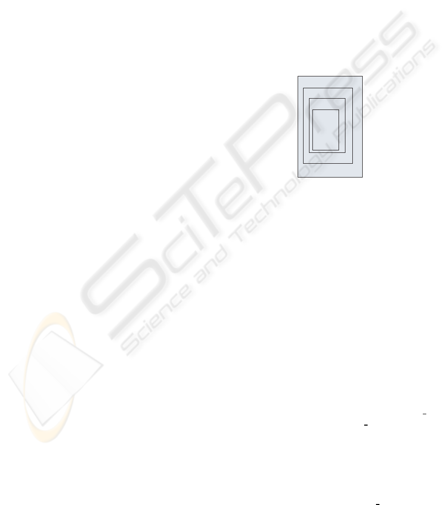
EA
View
Model
Construtor
Figure 1: Hierarchy of the EA Objects.
Our proposal is compatible with all frameworks,
methods and languages available in the EA domain.
As mentioned in the sections 2.1 to 2.3, we consider,
as shownin figure 1, that the EA has three types of ob-
jects: View, Model and Constructor. Each type of ob-
ject has different kinds of attributes: proper attributes,
synthesized and inherited attributes. The latter comes
from the objects in an upper level and lower level, re-
spectively.
As explained in sections 2.1 and 2.2, an EA com-
prises the definition of more than one aspect. Follow-
ing the IEEE recommended practice (IEEE, 2000),
we consider that an EA aspect is described as a view,
where each level of detail corresponds to a view. In
table 1 several frameworks and their corresponding
views are described.
Specification 1 describes the EA as a set of views.
Besides that, there are also attributes: method (me),
framework (fr), scope (sc), organization type (org t),
terms that characterize the EA (Ea d) and keywords.
The method attribute registers the method used in the
EA description process. The framework used in the
EA description is registered in the attribute frame-
work. The scope attribute registers the type of EA,
which can be the entire organization, a department or
a section description. The organization class is reg-
istered in the type of organization org type attribute.
TREEAD - A Tool that Enables the Re-use of Experience in Enterprise Architecture Description
337
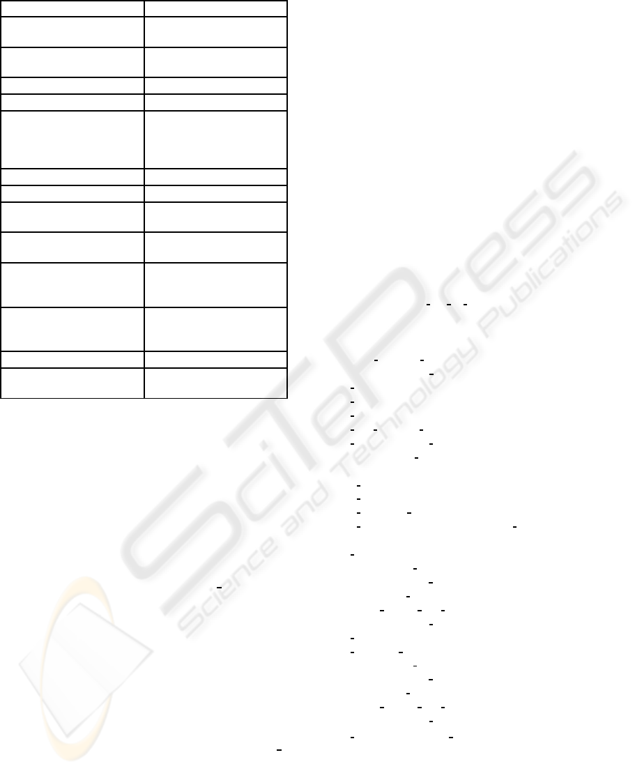
Table 1: Some Examples of framework’s views.
Framework Views
AMOS (Isaac and Leroy, 1994) Functional; Logical; Technical;
Organizational
BSP Information Architecture
(IBM, 1984)
Data
Process
Earl (Earl, 1989) Each element of the 4X4 matrix
Gartner Group (Handler, 2007) Each element of the 3X3 matrix
Rood (Rood, 1994) Strategy; Corporate culture;
People; Organization structure;
Technology; Information;
Processes; Tasks
IFW (IBM, 1995) Each element of all matrixes
Index (Boar, 1999) Each element of 4X4 matrix
Microsoft Solutions Framework
(Microsoft, 1999)
Business; Applications, Infor-
mation; Technology
Opdahl (Opdahl, 1996) Resources; Guidelines; Agents;
Activities; Responsabilities
Tapscott and Caston (Tapscott
and Caston, 1993)
Business view; Informa-
tion view; Technical view;
Applications view; Work view
Targowski and Rienzo (Tar-
gowski, 1996)
Data/Information; Software;
Communications networks;
Computer
TEAF (TEAF, 2000) Each element of 4X4 matrix
Zachman (Zachman and Sowa,
1992)
Each element of the 6X5 matrix
In the terms that characterizes the EA attribute a list
of terms that characterizes the organization to which
the EA is developed is registered. The keywords at-
tribute is synthesized from the view object and will
be described later on.
An EA aspect is described through one or more
view objects. Therefore, view objects can comprise a
set of models. The Specification 2 describes a View
object. This object has one proper attribute (aspect)
and the inherited attributes: method (me), framework
(fr), scope (sc), organization type (org
t), terms that
characterize the EA. The keywords attribute is synthe-
sized from the Model object.
An architect builds models to specify an EA as-
pect. The Model object, described in Specification
3, has the proper level and aspect (asp) attributes. For
example, for a Data Model the level attribute can have
one of the following values: conceptual, logical or
physical; the aspect attribute has the value data. Fur-
thermore, the Model object inherits the method (me),
framework (fr), scope (sc), organization type (org t),
terms that characterize the EA attributes. The key-
words and number of components (ncomp) attributes
are synthesized from the component constructor ob-
ject.
As explained in section 2.3, a constructor, de-
scribed in Specification 4 and 5, can be divided in
two types: component or connector. Generally, a
constructor has a name (name) and some character-
istics (Chs). For example, in the ER notation an at-
tribute has the following characteristics: data type,
length and type of attribute (normal, foreign key or
primary key). Furthermore, we associated to the Con-
structor object an attribute for storing keywords (Ks).
These keywords are used to contextualize the appli-
cation of the constructor. The constructor can belong
to another component or can aggregate other compo-
nents. In the supkeywords attribute and subkeywords
stores the keywords of the owner and owned construc-
tors, respectively. The relationship attribute stores in-
formation that concerns rules used in the modelling
task. For example, in modelling tasks decomposing
rules are applied. Keywords of linked constructors
are stored in the likeywords attribute. The relation
attribute stores data about relations with other con-
structors in a different View.
EA → me fra sc org
t Ea d S v.
EA.method = me.Value;
EA. framework = fra.Value;
EA.scope = sc.Value;
EA.org type = org t.Value;
EA.description = Ea d.description;
S v.method = me.Value;
S v. framework = fra.Value;
S v.scope = sc.Value;
S v.org type = org t.Value;
S v.description = Ea d.description;
EA.keywords = S v.keywords;
Ea d → des.
Ea
d.description = des.value;
Ea d → des Ea d.
Ea d
0
.description = concat(des.value, Ea d
1
.description);
S v → View.
View.method = S v.method;
View. framework = S v. framework;
View.scope = S v.scope;
View.org type = S v.org type;
View.description = S v.description;
S v.keywords = View.keywords;
S v → View S v.
View.method = S v.method;
View. framework = S v. framework;
View.scope = S v.scope;
View.org type = S v.org type;
View.description = S v.description;
S v
0
.keywords = concat(S v
0
.keywords, View.keywords);
Specification 1: EA object description.
After the grammar specification, we created the
TREEAD whose structure is shown in figure 2. The
tool has two major components: the client and the
server. The architect uses the client components: a
ICEIS 2010 - 12th International Conference on Enterprise Information Systems
338

browser and a software design tool. The browser
is used to communicate with the server component.
It is through the browser that the architect requests
for solutions to problems and stores EA descriptions.
Besides that, it is through the browser that the ar-
chitect configures the tools (method, framework and
languages) in the server. The server part is imple-
mented using Oracle technologies (Oracle, 2007) and
Microsoft ASPX technology (Ahmed et al., 2002).
View → aspect S m.
S
m.method = View.method;
S m. framework = View. framework;
S m.scope = View.scope;
S m.org type = View.org type;
S m.description = View.description;
View.aspect = aspect.Value;
S m.aspect = aspect.Value;
View.keywords = S m.keywords;
S m → Model.
Model.method = S m.method;
Model. framework = S m. framework;
Model.scope = S m.scope;
Model.org type = S m.org type;
Model.description = S m.description;
Model.aspect = S m.aspect;
S m.keywords = Model.keywords;
S m → Model S m.
Model.method = S m.method;
Model. framework = S m. framework;
Model.scope = S m.scope;
Model.org type = S m.org type;
Model.description = S m.description;
Model.aspect = S m.aspect;
S
m
0
.keywords = concat(S m
0
.keywords, Model.keywords);
Specification 2: View object description.
The 4Rs cycle proposed by Aamodt and Plaza
(Aamodt and Plaza, 1994) was implemented in the
server. The following modules were also imple-
mented: Software design tools library, XML parser,
Knowledge manager, Modelling manager, EA tools
manager and Views and modelling languages library.
The software design tools library has the parsing rules
that enable the parsing of XML files by XML parser.
The TREEAD’s users manage the contents of the
Case memory through Knowledge manager. In this
module the user can correct and disable previously
resolved problems. The Modelling manager is re-
sponsible the entire process of developing an EA de-
scription and it allows solutions to problems to be re-
quested and stores new EA descriptions. The EA tools
manager enables of new methods, views and lan-
guages to be configured. This module uses the meta-
case definition to specify the meaning for a view and
for a modelling language. The Views and modelling
languages library has the knowledge about each spe-
cific view and modelling languages as well as the con-
versation rules between different views and modelling
languages.
Model → asp level S
c.
Model.aspmodel = asp.Value;
Model.level = level.Value;
S c.method = Model.method;
S c. framework = Model. framework;
S c.scope = Model.scope;
S
c.org type = Model.org type;
S c.description = Model.description;
S c.aspect = Model.aspect;
S c.level = Model.level;
S c.aspmodel = asp.value;
S c.ncomp = 1;
Model.keywords = S c.keywords;
S c → Co.
Co.method = S c.method;
Co. framework = S c. framework;
Co.scope = S c.scope;
Co.org type = S c.org type;
Co.description = S c.description;
Co.aspect = S c.aspect;
Co.level = S c.level;
Co.asplevel = S c.asplevel;
Co.ncomp = S c.ncomp;
S c.keywords = Co.keywords;
S c → Co S c.
Co.method = S c.method;
Co. framework = S c. framework;
Co.scope = S c.scope;
Co.org type = S c.org type;
Co.description = S c.description;
Co.aspect = S
c.aspect;
Co.level = S c.level;
Co.asplevel = S c.asplevel;
Co.ncomp = S c.ncomp;
S c
0
.keywords = concat(S c
1
.keywords, Co.keywords);
Specification 3: Model object description.
It is important to notice that in the retrieval and re-
tention phases clustering techniques (Tan et al., 2006)
are used. These techniques were used to enable a
faster case retrieval. Access to the case-memory is
achieved by using Groups of cluster links as shown in
figure 2. This strategy significantly reduces the num-
ber of case assessments and consequently retrieval
time.
Considering the specifications illustrated in 1 to
5, the TREEAD comprises four types of cases: EA,
View, Model and Constructor. For each type of case,
the case’s characteristics are the object’s attributes
(proper, inherited and synthesized). The case’s solu-
tion part is the description of each object. The de-
scription of each object is done in XML, a widely
TREEAD - A Tool that Enables the Re-use of Experience in Enterprise Architecture Description
339
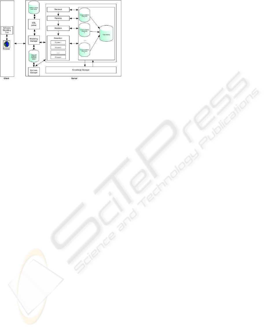
Figure 2: TREEAD’s structure.
used language.
We used TREEAD for the specification of Zach-
man’s cell (Owner, Data) to create three examples in
different contexts:
• Example 1: fifteen data models for different orga-
nization departments (such as sales, accounting,
manufacturing and so on);
• Example 2: six data models of six hospital medi-
cal services;
• Example 3: nine data models of the same depart-
ment (sales department).
Co →
′
component
′
name Chs Ks Sup Sub Re Li Ore.
Co.type =
′
component
′
;
Co.name = name.value;
Co.characts = Chs.characts;
Co.keywords = Ks.keywords;
Co.supkeywords = Sup.keywords;
Co.subkeywords = Sub.keywords;
Co.relationship = Re.relationship;
Co.likeywords = Li.keywords;
Co.noflinks = Li.number;
Co.relation = Ore.number;
Co.ncomp = Co.ncomp+ 1;
Specification 4
: Constructor object description.
A
ll the data models were specified using the IDEF1X
in the PowerDesigner (Sybase, 2006) software tool.
The models developed in examples 1) and 3) were de-
fined by different IT professionals while the models
developed in example 2) were defined by only one IT
professional. A total of thirty data models, as shown
in table 2, were used to evaluate the TREEAD tool.
In this experimental study we want to measure the
re-utilization of the tool. Then each model within
each example was introduced sequentially according
to the order specified in the table.
Figure 3 presents the results of Example 1) where
the models belong to different departments types and
were created by different IT professionals. Despite
the diversity of the data models, there is a mean per-
centage of re-use, around 44% and 23% for connec-
tors and components respectively. It also has to be
noticed that the percentage does not decrease with an
increasing number of models in the case memory.
Co →
′
connector
′
name Chs Ks Sup Sub Re Li Ore.
Co.type =
′
connector
′
;
Co.name = name.value;
Co.characteristics = Chs.characteristics;
Co.keywords = Ks.characteristics;
Co.supkeywords = Sup.keywords;
Co.subkeywords = Sub.keywords;
Co.relationship = Re.relationship;
Co.linkeywords = Li.keywords;
Co.relation = Ore.number;
Co.likeywords = Lid.keywords;
Chs → name val.
Chs.characts = (name.value, val.value);
Chs → name val Chs.
Chs
0
.characts = concat(Chs
1
, (name.value, val.value));
Ks → val.
Ks.keywords = val.value;
Ks → val Ks.
Ks
0
.keywords = concat(Ks
1
, val.value);
Sup → Ks.
Sup.keywords = Ks.value;
Sub → Ks
Sub.keywords = Ks.value;
Re → name Ks.
Re.relationship = (name.value, Ks.value);
Li → Ks.
Li.keywords = Ks.value;
Li → Ks Li.
Li
0
.keywords = concat(Li
1
.keywords, Ks.value);
Ore → ε.
Ore → name.
Ore.relation = name.value;
Ore → name Ore.
Ore
0
.relation = concat(Ore
1
.relation, name.value);
Specification 5
: Constructor object description.
F
igure 4 shows the results of Example 2) where
the models belong to departments with identical pur-
poses and were defined by the same IT professional.
We can see that the percentage of re-utilization is
high, above 52% and 83% for connectors and com-
ponents respectively. This result has to be expected
considering the similarities of the departments and the
consistency of the modelling phase. And it is shown
that the percentage of re-use increases with the num-
ber of cases in memory.
Figure 5 presents the results of Example 3) where
ICEIS 2010 - 12th International Conference on Enterprise Information Systems
340
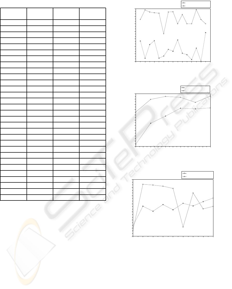
Table 2: Number of constructors of each data model.
Model Example N. of comp. N. of connect.
M
1
1 14 7
M
2
1 135 63
M
3
1 176 23
M
4
1 80 19
M
5
1 70 17
M
6
1 81 6
M
7
1 161 23
M
8
1 106 25
M
9
1 41 5
M
10
1 103 13
M
11
1 36 5
M
12
1 31 5
M
13
1 210 87
M
14
1 20 7
M
15
1 88 5
M
16
2 281 69
M
17
2 406 93
M
18
2 367 78
M
19
2 391 88
M
20
2 230 61
M
21
2 89 394
M
22
3 73 19
M
23
3 112 33
M
24
3 112 29
M
25
3 58 12
M
26
3 40 9
M
27
3 78 17
M
28
3 55 12
M
29
3 51 11
M
30
3 61 15
the models belong to the same department and were
created by different IT professionals. We can see that
the percentage of re-utilization is above 37% and 43%
respectively for connectors and components respec-
tively. This result illustrates that the consistency in the
modelling phase influences the outcome. The number
cases in the memory is not always related to a high-
percentage of re-use, at least in terms of the re-use of
connectors.
4 CONCLUSIONS
In this paper we proposed a software tool - TREEAD,
based on CBR techniques, which enables the re-use of
experience in EA description. This work also presents
a careful synthesis of methods, frameworks and mod-
elling languages used in EA description. Considering
the reviewed frameworks, methods and languages the
0 2 4 6 8 10 12 14 16
15
20
25
30
35
40
45
50
Results of example 1
Data model
Adaptation Percentage
Adapted connectors
Adapted attributes and entities
Figure 3: Results of example 1.
16.0 16.5 17.0 17.5 18.0 18.5 19.0 19.5 20.0 20.5 21.0
50
55
60
65
70
75
80
85
90
95
100
Results of example 2
Data model
Adaptation percentage
Adapted connectors
Adapted attributes and entities
Figure 4: Results of example 2.
22 23 24 25 26 27 28 29 30
30
40
50
60
70
80
90
100
Results of example 3
Data model
Adaptation percentage
Adapted connectors
Adapted attributes and entities
Figure 5: Results of example 3.
structure of four EA objects in GA formalism is pre-
sented.
The proposed TREEAD supports the use of
several EA frameworks, methods, modelling lan-
guages and software modelling tools. Furthermore,
TREEAD applies Clustering techniques to improve
retrieval case time.
Finally we presented the results of the application
of TREEAD in three different examples. In spite of
TREEAD - A Tool that Enables the Re-use of Experience in Enterprise Architecture Description
341

the diversity of the models due to different origins or
different strategies of modelling, the percentage of re-
use was always above 33% and 15% for connectors
and components respectively. The results obtained
lead us to conclude that the use of experience in EA
description can contribute to a better system develop-
ment.
REFERENCES
Aamodt, A. and Plaza, E. (1994). Case-based reasoning:
Foundational issues, methodological variations and
systems approaches. AI-Communications, 7(1):39–
52.
Agilense (2007). Agilense enterprise architecture frame-
works.
Ahmed, M., Garret, C., FairCloth, J., and Payne, C. (2002).
ASP.NET Web Developers’s Guide. Syngress Publish-
ing.
Alamos, L. (1994). Information architecture: The founda-
tion. Technical report, Los Alamos National Labora-
tory.
Amdahl, G. M., Blaauw, G. A., and Brooks, F. P. (1964).
Architecture of the ibm system/360. IBM Journal,
8(2):87–101.
Barker, R. (1995). Case*Method - Entity Relationship Mod-
elling. Addison-Wesley.
Barker, R. and Longman, C. (1992). Case*Method - Func-
tion and Process Modelling. Addison-Wesley.
Bernus, P., Mertins, G., and Schmidt, G. (1998). Handbook
On Architectures of Information Systems. Springer-
Verlag.
Boar, B. H. (1999). Constructing Blueprints for Enterprise
IT Architectures. John Wiley & Sons, Inc.
Capgemini (2006). Architecture and the integrated
architecture framework. Technical report,
Capgemini - Consulting, Technology, Outsourc-
ing. www.capgemini.com, Consulted in October
2007.
Chaiyasut, P. and Shanks, G. (1994). Conceptual data mod-
elling process: A study of novice and expert data mod-
ellers. In Halpin, T. and Meersman, R., editors, First
International Conference on Object-Role Modelling,
pages 310–323, Brisbane - Queensland.
Chapin, N. (1970). Flowcharting with the ansi standard: A
tutorial. Computing Surveys, 2(2).
Chen, P. P.-S. (1976). The entity-relationship model - to-
ward a unified view of data. ACM Transactions on
Database Systems, 1(1):9–36.
CIO (1999). Enterprise architecture conceptual framework.
Technical report, CIO Council. Federal Conceptual
Model Subgroup.
Earl, M. J. (1989). Management Strategies For Information
Technology. Prentice Hall.
EE (2005). Repository-centric enterprise architecture.
white paper.
Eertink, H., Janssen, W., and Luttighuis, P. O. (1999). A
business process design language. In World Congress
on Formal Methods in Development of Computing
Systems, pages 708–727, Toulose - France. Springer.
FIPS (1993). Integration Definition for Information Model-
ing (IDEF1X). Federal Information Processing Stan-
dards Publications.
Gane, C. and Sarson, T. (1979). Structured Systems Analy-
sis: Tools and Techniques. Prentice-Hall.
GAO (2006). Enterprise architecture: Leadership remains
key to establishing and levearing architectures for or-
ganizational transformation. Technical report, Chair-
man, Committee on Governmentm Reform, House of
Representatives.
Garlan, D., Allen, R., and Ockerbloom, J. (1995). Archi-
tectural mismatch: Why resuse is so hard. IEEE Soft-
ware, 12(6):17–26.
Gore, M. (2003). Thoughs on the information system archi-
tect role. In ITC’03, pages 706–710. IEEE - Computer
Society.
Group, O. (2002). The open group architectural framework.
Technical report, The Open Group. Verso 8.
Handler, R. (2007). Closing the gap between architecture
and model-driven development. In Gartner Enterprise
Architecture Summit, London, UK. Gartner.
IBM (1984). Business Systems Planning: Information Sys-
tems Planning Guide. IBM Corperation.
IBM (1995). Information Framework (IFW) Description.
IBM, 1.02 edition.
IEEE (2000). IEEE Recommended Practice for Archi-
tectural Description of Software-Intensive Systems.
IEEE.
IFEAD (2005). Trends in enterprise architecture 2005: How
are organizations progressing.
IFEAD (2007). Enterprise architecture tools review.
www.enterprise-architecture.info/EA tools.htm, Con-
sulted at 27-12-2007.
Isaac, J. C. and Leroy, D. (1994). The amos study: Toward a
user validation of the cis architecture design. In BRG
Symposium on C2 Research, California.
Isaac, J. C. and Leroy, D. (1995). Architecture modeling for
better requirements and system specification. In First
International Symposium on Command and Control
Research and Technology, Washington D. C.
ISO/IEC (1998). Information technology - open distributed
processing - reference model: Overview.
Kim, Y. G. and Everest, G. C. (1994). Building an is archi-
tecture collective wisdom from the field. Information
& Management, 26:1–11.
Lankhorst, M., Iacob, M., Jonkers, H., Torre, L., Proper, H.,
Arbab, F., Boer, F., Bonsangue, M., Hoppenbrouw-
ers, S., Zanten, G., Groenewegen, L., Buuren, R.,
Slagter, R., Campschoer, J., Arbab, F., Steen, M.,
Stam, A., Wieringa, R., Eck, P., Krukkert, D., Doest,
H., Leeuwen, D., Fennema, P., Bosma, H., Cuvelier,
ICEIS 2010 - 12th International Conference on Enterprise Information Systems
342

M., Penders, P., Bekius, S., and Janssen, W. (2005).
Enterprise Architecture at Work: Modelling, Commu-
nication and Analysis. Springer.
Lankhorst, M., Jonkers, H., Buuren, R., Leeuwen, D., and
Doest, H. (2004). Enterprise architecture modelling -
the issue of integration. Advanced Engineering Infor-
matics, 18(4):205–216.
Lloyd-Williams, M. (1994). Expert system support for
object-oriented database design. International Jour-
nal of Applied Expert Systems, 1(3).
Maier, M. W. (1996). Systems architecting: An emergent
discipline? In IEEE Aerospace Applications, vol-
ume 3, pages 231–246.
McDavid, D. W. (1999). A standard for business architec-
ture description. IBM Systems Journal, 38(1):12–31.
Medvidovic, N. and Taylor, R. N. (2000). A classification
and comparison framework for software architecture
description languages. IEEE Transactions on Soft-
ware Engineering, 26(1):70–93.
Microsoft (1999). Microsoft solutions framework. White
Paper.
NIH (2007). Nih enterprise architecture framework. Tech-
nical report, National Institutes of Health.
NIST (1989). Information management directions: The
integration challenge. Technical report, Institute of
Standards and Technology.
Nolan, R. L. and Mulryan, D. W. (1987). Undertaking an
architecture program. Stage By Stage, 7(2).
OMG (2004). Business process modeling notation specifi-
cation. Technical report, Object Management Group.
OMG (2007). Unified modeling language: Superstructure.
Technical report, Object Management Group.
Opdahl, A. L. (1996). A model of the is-architecture align-
ment problem. In Lind, M., Axelsson, K., Goldkuhl,
G., and Hedberg, P., editors, VITS Autumn.
Oracle (2007). www.oracle.com.
Panet, G. and Letouche, R. (1994). Merise / 2: Modles et
Techniques Merise Avancs. Les ditions D’ Organisa-
tion.
Rechtin, E. (1991). Systems Architecting: Creating &
Building Complex Systems. Prentice Hall.
Rechtin, E. (1999). Systems Architecting Of Organizations:
Why Eagles Can’t Swim. CRC Press.
Rechtin, E. and Maier, M. W. (1997). The Art of Systems
Architecting. CRC Press.
Rood, M. A. (1994). Enterprise architecture: Definition,
content, and utility. In Third Workshop on Enabling
Technologies: Infrastructure for Collaborative Enter-
prises, pages 106–111, Morgantown, USA. IEEE.
Ryan, H. and Santucci, J. (1993). Building an enterprise
information architecture. Infoworld, pages 57–58.
Scheer, A.-W. (1998). ARIS - Business Process Frame-
works. Springer-Verlag, 2ł edition.
Scheer, A.-W. (1999). ARIS - Business Process Modeling.
Springer-Verlag, 2ł edition.
SEI (2003). How do you define software architecture -
www.sei.cmu.edu/architecture/definitions.html. Con-
sulted in 1-07-2003.
Shah, H. and Kourdi, M. E. (2007). Frameworks for enter-
prise architecture. IT PrO, September — October:36–
41.
Spewak, S. H. and Hill, S. C. (1995). Enterprise Architec-
ture Planning, Developing a Blueprint for Data, Ap-
plications and Technology. John Wiley & Sons, Inc.
Stecher, P. (1993). Building business and application sys-
tems with retail application architecture. IBM Systems
Journal, 32(2):278–306.
Sybase (2006). www.sybase.com/products/.
Sykes, J. B. (1991). The Concise Oxford Dictionary. Oxford
University Press.
Tan, P. N., Steinbach, M., and Kumar, V. (2006). Introduc-
tion to Data Mining. Pearson Education.
Tandon, R. (2007). The role of solution architects in sys-
tems integrations. IT PrO, March, April:26–33.
Tapscott, D. and Caston, A. (1993). Paradigm Shift: The
New Promise of Information Technology. McGraw-
Hill.
Targowski, A. S. (1996). Global Information Infrastruc-
ture: the Birth, Vision and Architecture. Idea Group
Publishing.
Tauzovich, B. (1990). An expert system for conceptual
data modelling. In 8th International Conference on
the Entity-Relationship Approach, Toronto, Canada.
TEAF (2000). Treasury enterprise architecture framework.
Technical report, Department of Treasury.
Technology, N. I. S. (1993). Integration Definition for
Function Modeling (IDEF0). Federal Information
Processing Standards Publications.
Wilhelm, R. and Maurer, D. (1996). Compiler Design.
Addison-Wesley.
Zachman, J. A. (1987). A framework for information sys-
tems architecture. IBM Systems Journal, 26(3):276–
292.
Zachman, J. A. and Sowa, J. F. (1992). Extending and for-
malizing the framework for information systems ar-
chitecture. IBM Systems Journal, 31(3):590–616.
Zwegers, A. (1998). On Systems Architecting - a study in
shop floor control to determine architecting concepts
and principles. Ph.d thesis, Technische Universiteit
Eindhoven. ISBN 90-386-0699-4.
TREEAD - A Tool that Enables the Re-use of Experience in Enterprise Architecture Description
343
