
STRUCTURED USE-CASES AS A BASIS FOR SELF-MANAGEMENT
OF DISTRIBUTED SYSTEMS
Reza Haydarlou, Michel Oey, Martijn Warnier and Frances M. T. Brazier
Faculty of Technology, Policy and Management, Delft University of Technology, Jaffalaan 5, Delft, The Netherlands
Keywords:
Autonomic computing, Distributed systems, Self-management.
Abstract:
Automated support for management of complex distributed object-oriented systems is a challenge: self-
management of such systems the goal. This paper presents a use-case based approach to self-management
of such systems, focusing on autonomic monitoring and diagnosis. The existing notion of use-case has been
extended to different levels of system design: explicitly specifying system behavior at different levels, and the
relations between these levels, coupling structural models to these descriptions when and where appropriate.
The proposed model is illustrated with a small example.
1 INTRODUCTION
The complexity of software systems, especially dis-
tributed systems, increases significantly day by day.
As a result, management and maintenance of such
complex systems have become a serious problem.
Autonomic computing (Ganek and Corbi, 2003;
Kephart and Chess, 2003) is a solution proposed
to automate management (self-management), and to
reduce the cost of maintenance of distributed sys-
tems. In the autonomic computing architectural
blueprint (IBM Corporation, 2005), a number of ar-
chitectural building blocks are distinguished of which
managed resources and autonomic managers are cen-
tral.
Figure 1 presents a high-level architecture of
a self-management framework (Haydarlou et al.,
2006a; Haydarlou et al., 2006b) for distributed object-
oriented systems. In line with the autonomic com-
puting architectural blueprint two modules are dis-
tinguished: a managed-system and an autonomic-
manager. In the approach proposed in this pa-
per the managed-system is an existing distributed
object-oriented application extended with sensors and
effectors. The autonomic-manager adds the self-
management capability to the system. It has two
modules: (1) a self-diagnosis module, and (2) a
self-adaptation module. The self-diagnosis module
continuously checks whether the running application
shows any abnormal behavior by monitoring the val-
ues it receives from the sensors placed in the appli-
cation. If so, the self-diagnosis module determines a
diagnosis and passes it to the self-adaptation module.
The self-adaptation module is responsible for plan-
ning actions to resolve abnormal behavior, using the
effectors to this purpose.
Sensored Values
Managed Resource
Managed System
Adaptation Instructions
Analysis &
Diagnosis
Planning &
Adaptation
Diagnosis
Autonomic Manager
Self−adaptation ModuleSelf−diagnosis Module
Figure 1: Self-management architecture.
This paper presents a self-management framework
based on system use-cases, i.e., descriptions of a sys-
tem’s desired behavior. To monitor system behavior
and to repair abnormal behavior, the framework uses
knowledge of the internal structure and dynamic be-
havior of the running application.
The remainder of the paper is organized as fol-
lows: the next section describes the two perspectives
(structural and behavioral) that can be used to de-
scribe distributed systems. Section 3 argues for the
behavioral perspective as the unit of management for
distributed systems and Section 4 gives an extension
to use-cases that makes them more suitable as a basis
198
Haydarlou R., Oey M., Warnier M. and M. T. Brazier F. (2010).
STRUCTURED USE-CASES AS A BASIS FOR SELF-MANAGEMENT OF DISTRIBUTED SYSTEMS.
In Proceedings of the 5th International Conference on Software and Data Technologies, pages 198-205
DOI: 10.5220/0002981001980205
Copyright
c
SciTePress
for autonomic management. Section 5 gives a brief
example of a managed system and illustrates our ap-
proach. The paper ends with a discussion and conclu-
sions.
2 STRUCTURE AND BEHAVIOR
Conceptually, each system has an internal structure
and is designed to exhibit specific behavior. The
structure of a system refers to the building blocks
of a complex, distributed system, such as servers,
runnables, components, and classes. Consider, for
example, Trading Systems in a bank environment.
These systems consist of several servers, often in-
cluding at least one web server, (e.g., to allow cus-
tomers to communicate with the bank), and at least
one database server (e.g., to store account information
on customers and their shares). The servers together
with their (inter)connections form the systems’ struc-
ture.
System behavior describes the purpose of the
(combination of) processes for which a system has
been designed. In the above case, the system was de-
signed to process customer transactions to buy and/or
sell shares.
2.1 Structural Perspective
Many business enterprises run their distributed soft-
ware systems on a large number of heterogeneous
machines each with their own specific operating sys-
tem(s), middleware, software tools, libraries and sup-
port for specific communication protocols. This dis-
tributed infrastructure is dynamic, changing contin-
ually. Each individual machine has a considerable
number of configuration parameters specifying its
address, maximum number of allowed connections,
connection time-out values, etc.
A typical example of a distributed system can be
found in business enterprises that enable customers to
reach the company’s system through a browser from
their homes. To support this functionality, the com-
pany runs one or more firewalls to secure their sys-
tems. Behind these firewalls run multiple servers,
such as the actual web server, an authentication server
that ensures that only authorized and authenticated
customers can enter, an application server, a database
server, message queue server, file server, etc.
Each of these servers can be considered as struc-
tural elements within the structure of the entire dis-
tributed system. Note that structural elements do not
refer to individual hardware components but to soft-
ware systems. Each of the servers typically run on
one or multiple hardware devices (computers) that are
all connected through some internal network. For ex-
ample, a database server could be distributed and/or
replicated across multiple computers.
2.2 Behavioral Perspective
In practice, the actions a system performs, defining
its execution behavior, are designed by multiple par-
ties. Use-cases introduced by Jacobson (Jacobson,
1992), currently a common requirements modeling
and structuring instrument, provide a means to de-
scribe a system’s desired behavior. Although there is
no single universally accepted definition of a use-case
in the literature, there is a general acceptance that ‘a
use-case is a collection of possible sequences of inter-
actions between the system and external actors having
a set of main goals to be reached with the help of the
system’ (Cockburn, 2001; Jacobson, 1992; Fowler,
2003).
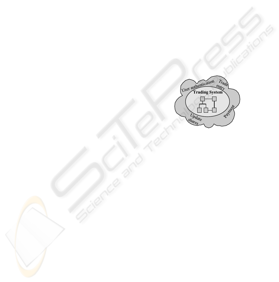
Figure 2: Use-cases of an example Trading System.
As an example consider the Trading System,
briefly described above. The use-cases defining this
system’s desired behavior include User Authentica-
tion (a user authenticates him/herself to the system),
Trade Entry (a user enters a trade in the system),
Payment (a user requests the system to adminis-
trate his/her payment regarding a trade), and Update
Shares (a user requests the system to update his/her
shares).
Figure 2 shows a graphical representation of this
Trading System with its use-cases. The system is de-
picted as an ellipse containing a number of squares
representing the structural elements of the system.
The continuous lines connecting the squares show
their structural relationships. The example illustrates
that system behavior can be considered as a collec-
tion of use-cases and a use-case can be seen as a unit
of behavior (behavioral element).
Use-cases are most often expressed in a semi-
formal way (referred to as use-case template or use-
case notation). For our purpose, use cases should in-
clude the following basic characteristics:
1. A use-case name that uniquely identifies the use-
case and clearly expresses its goal.
STRUCTURED USE-CASES AS A BASIS FOR SELF-MANAGEMENT OF DISTRIBUTED SYSTEMS
199
2. A list of use-case actors. Use-case actors are
other systems or persons who initiate interactions
with the system to achieve their goals.
3. A use-case trigger which is the event (external,
internal, or temporal) that causes a use-case to be
initiated.
4. A list of use-case pre-conditions that specifies the
conditions (i.e., a certain system state) that must
be true for a trigger to meaningfully cause the ini-
tiation of a use-case.
5. A list of use-case post-conditions that specifies
the desired system states on use-case completion.
6. A list of use-case steps. Use-case steps are ei-
ther interactions between a system (or part of a
system) and an actor, or references to other use-
cases. References are used to delegate certain sub-
goals to these referenced use-cases (Kosters et al.,
1997).
Note that, for our purpose of system management, a
use-case is a description of a process in which a sys-
tem receives a request, executes use-case steps inter-
nally by means of structural elements (e.g., system’s
sub-systems, components), and produces a response.
3 UNIT OF SELF-MANAGEMENT
Self-managing systems often involve multiple auto-
nomic managers. Each autonomic manager focuses
on managing one specific part of a system, thereby
keeping the autonomic managers themselves manage-
able. However, one important question is: ‘What is
the most appropriate unit of self-management?’
The answer to this question depends on how one
views a system. The previous section discussed two
possible perspectives:
• structural perspective - a system is a collection
of structural elements (servers), on each of which
a sub-process (an activity) of a business (or non-
business) process runs.
• behavioral perspective - a system is a collection
of behavioral elements (business or non-business
processes), each of which is realized by a number
of structural elements.
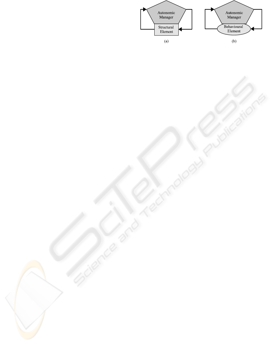
The choice between these two perspectives leads to
the choice of the unit of self-management: associate
an autonomic manager with a structural element or a
behavioral element (see Fig. 3).
Typically, the structural perspective is chosen,
with the structural element as the unit of self-
management. For example, each server (e.g.,
Figure 3: What is the unit of self-management: (a) a struc-
tural element or (b) a behavioral element.
database server, web-server, application server) in a
distributed system is managed by a separate auto-
nomic manager.
This paper, however, proposes to choose the be-
havioral perspective, with the behavioral element
(as described by a use-case) as the unit of self-
management. Each functional behavior of a system is
thus managed by an autonomic manager. The advan-
tage of the behavioral perspective is that autonomic
managers can use contextual knowledge to diagnose
faulty/abnormal behavior and to recover from sys-
tem malfunctions (van Harmelen and ten Teije, 1994;
Palma and Mar
´
ın, 2002; Jiang et al., 2009).
3.1 Availability of Contextual
Knowledge
Diagnosing the root-cause of a system malfunction
is a crucial management task (Peischl and Wotawa,
2003; Khanna et al., 2007). Generally speaking, a
root-cause is the initiating cause of a causal chain.
The primary goal of root-cause diagnosis is to under-
stand why and how a malfunction has occurred, de-
termining which part of a use-case caused a system
malfunction, and under which conditions. Without a
proper diagnosis, an autonomic manager is not able to
construct and perform appropriate remedy plans.
The autonomic manager infers its diagnoses re-
garding a system malfunction on the basis of infor-
mation that it obtains from the system during its ex-
ecution. This information is sent to the autonomic
manager by sensors instrumented in the system and
informs the autonomic manager of the status of spe-
cific parts of the system. The obtained information
should be analyzed and interpreted in the light of a
certain context.
Choosing to associate an autonomic manager with
each use-case (i.e., behavioral element, process) pro-
vides an autonomic manager with exactly this contex-
tual knowledge whereas associating it with a struc-
tural element does not. To clarify, suppose the Trade
System has two use-cases: buy shares and sell shares,
which buy and sell shares for a customer, respectively.
During the execution of either use-case, the system
ICSOFT 2010 - 5th International Conference on Software and Data Technologies
200
internally uses a number of its servers, including its
database server. Both use-cases are examples of be-
havioral elements and the database server is an exam-
ple of a structural element.
Associating autonomic managers with structural
elements would mean that the database server has a
separate autonomic manager that would monitor the
activities of the database server. Consequently, if a
system malfunction occurs within the database server
during the execution of one of the use-cases, the cor-
responding autonomic manager would detect the fail-
ure. However, it would not have information on which
use-case was running: it lacks the contextual knowl-
edge. Whereas if the use-case was the unit of self-
management, each use-case would have its own as-
sociated autonomic manager. In that case, a failure
in the database server would be detected by the au-
tonomic manager of the currently executing use-case.
In other words, it has the contextual knowledge.
Having contextual knowledge has two benefits.
First, after a failure occurs, this knowledge helps to
identify the root cause, and consequently, allows rem-
edy plans to recover from the failure and/or to pre-
vent similar failures from occurring in the future. The
contextual knowledge provides the diagnosis process
with information on which use-case was being exe-
cuted when the failure occurred, and even the use-case
step within the use-case. Knowing how the system
was expected to behave (the use-case) is of great help
when determining the root cause of a failure.
The second benefit of contextual knowledge is that
it also helps to prevent system failures more effec-
tively as it enables an autonomic manager to more ac-
curately monitor the correct and consistent execution
of a use-case. To illustrate, selling or buying shares
are two different use-cases, with different pre- and
post-conditions. For example, the autonomic man-
ager can monitor that the change to the number of
shares should be positive if shares are being bought,
and negative if shares are being sold
1
. If this check
fails, the autonomic manager can intervene and per-
form remedy actions before the actual failure occurs
in the managed system.
Unfortunately, use-cases in their current form do
not relate their use-case steps to the structural ele-
ments in which they are executed. Consequently, au-
tonomic managers that base their managed units on
use-cases can provide contextual knowledge needed
for proper problem determination, but lack the abil-
1
For clarity, a very simple example has been chosen.
Unfortunately, it does not illustrate the full potential of
monitoring the use-case execution with autonomic man-
agers. In practice, such a simple check would typically be
done by the managed system itself.
ity to precisely pinpoint the structural element where
a malfunction has occurred. In contrast, autonomic
managers that base their managed units on structural
elements do not have enough contextual information
to give a precise diagnosis of faulty systems behav-
ior. The next section discusses how use-cases can be
extended to indicate both the activity (in the context
of a behavior) that is responsible for a system mal-
function, and the place (structural element) where a
malfunction has occurred.
3.2 Extending Use-cases with Structural
Information
Basing autonomic management on use-cases, which
describe the behavior of a system – the perspective
chosen in this paper, is not sufficient. Use-cases are
executed by processes that run within the managed
system. More precise, these processes run within
structural elements of the system. Autonomic man-
agement requires specification of the relation between
processes and the structural elements in a structural
model of a system. Note that the executions of differ-
ent use-cases may be implemented by different pro-
cesses, which run within different structural elements.
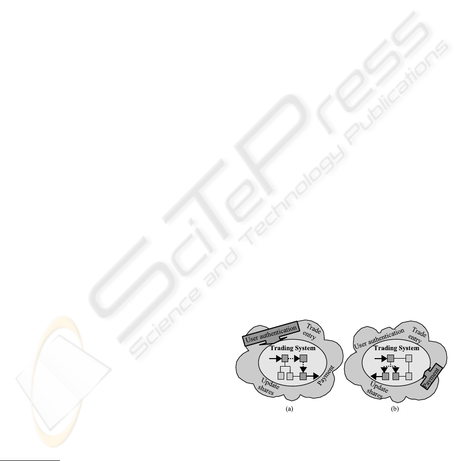
Figure 4 shows that the activation of a specific use-
case is mirrored in the activation of related structural
elements in the structural model as shown by the high-
lighted structural elements. Dashed arrows represent
the information flow between different structural el-
ements. Continuous arrows represent the input and
output of a use-case, respectively. Figure 4(a) de-
picts the structural elements activated when the User
Authentication use-case within the Trading System is
executed, and Figure 4(b) shows that other structural
elements are activated when the Payment use-case is
executed.
Figure 4: Use-cases and structural elements.
Use-case descriptions, as presented in Section 2.2,
do not contain references to structural elements. This
paper proposes to extend use-case descriptions with
the following:
7. A list of use-case structural elements specifying
the structural elements responsible for execution
STRUCTURED USE-CASES AS A BASIS FOR SELF-MANAGEMENT OF DISTRIBUTED SYSTEMS
201

of a number of use-case steps. Each use-case is
related to a number of structural elements, each
use-case step is executed by exactly one structural
element.
This extension, in principle, integrates the structural
and behavioral perspectives in one use-case descrip-
tion.
For self-management to work, autonomic man-
agers need to be able to monitor a managed system
while it is running. Sensors in a managed system pro-
vide an autonomic manager with run-time informa-
tion when executing use-cases. An autonomic man-
ager analyzes this information to determine whether a
system is functioning as intended.
Ideally, sensors are placed automatically in the
code of the system (Luk et al., 2005) given the use-
case descriptions, providing an autonomic manager
information on both the behavioral and structural ele-
ments involved.
4 STRUCTURING USE-CASES
As the number of use-cases of a complex distributed
system can be significant, and the complexity of these
use-cases can vary noticeably, additional structure is
needed. There are two ways to structure use-cases:
use-case levels and use-case references.
4.1 Use-case Levels
During system design use-cases are used for require-
ments modeling and structuring, distinguishing dif-
ferent levels of process design. The first level of
process description, the initial use-case specification,
describes the behavior of a system as a whole in a
system-level use-case. This use-case specification is
the basis for the design of a system at more detailed
levels. For the purpose of simplicity in this paper
specifications at all levels are referred to as use-cases.
Runnable-level use-cases are the next level of
specification, defining interactions between systems.
These use-cases describe the internal behavior of the
system as interactions between runnables (e.g., pro-
cesses). At a more detailed level component-level
use-cases describe behavior as interactions between
software components. At class-level use-cases define
sequences of method-invocations.
The four above mentioned levels correspond to the
different positions often found within an organisation
(i.e., system architects, system administrators, func-
tional analysts, system developers).
4.2 Use-case References
Use-case references are used to define the relations
between use-cases. Each use-case step (see Sec-
tion 2.2) can be a reference to another use-case at the
same level or at another level (lower or higher). Such
references allow a complex use-case to be decom-
posed into multiple, less complex, (sub)use-cases,
which, in turn, can be further decomposed in even
smaller use-cases, etc. Furthermore, references also
allow use-cases to be ‘re-used’: multiple use-cases
can refer to the same (sub)use-case, if they need the
same behavior. Figure 5 illustrates this.
Use-case steps, including references to other use-
cases, are executed by structural elements. A dashed
arrow in Figure 5, originating from a structural ele-
ment (SEi ) and ending at a behavioral element (BEi ),
represents the communication between use-cases at
the same or different levels. For example, at the
runnable level, the dashed arrow (horizontal refer-
ence) from SE2 to BE2 shows that the use-case step of
behavioral element (use-case) BE1 that runs on struc-
tural element SE2 is an invocation of behavioral ele-
ment BE2 at the same level.
A dashed arrow from a higher level to a lower
level, in Figure 5, represents the downward communi-
cation between use-cases at different levels. There is
a compositional relationship between a structural el-
ement executing a downward reference of a use-case
at a higher level and the structural elements execut-
ing the use-case steps of the referenced use-case at
the lower level. For instance, structural element SE1,
at the runnable level, consists of structural elements
SE4, SE5, and SE6 at the component level. When
the downward reference executes on SE1, the system
switches to the execution of use-case BE3 executed
by the components SE4, SE5, and SE6.
A dashed arrow from a lower level to a higher
level represents the upward communication between
use-cases at different levels. For instance, use-case
BE6, at the class level, needs functionality of a li-
brary (component) that is executed by use-case BE4
in structural element SE5 at the component level. The
invocation statement executed within SE9 is an up-
ward reference. Note that there is no compositional
relationship between a structural element executing
an upward reference of a use-case at a lower level and
the structural elements executing the use-case steps of
the referenced use-case at the higher level.
Section 5 gives examples of both use-case levels
and use-case references.
ICSOFT 2010 - 5th International Conference on Software and Data Technologies
202
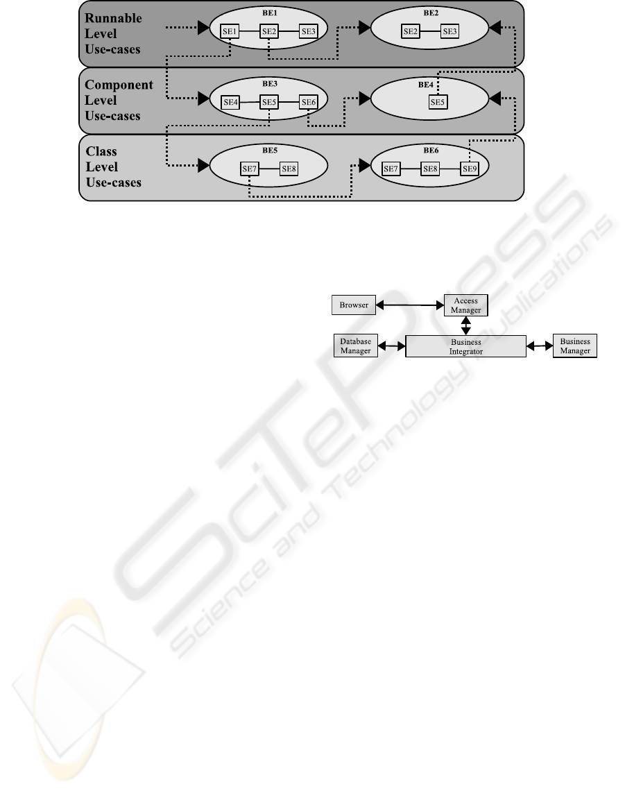
Figure 5: Various use-case levels and their relationships. Horizontal and vertical references between use-cases are shown.
4.3 Relationships between Autonomic
Managers
Each autonomic manager manages its own use-case
(its managed system). However, as use-cases can ref-
erence other use-cases, autonomic managers need to
be able to communicate with each other. Success or
failure of use-case execution must be communicated
to the autonomic manager of the referencing use-case,
to locate the root cause of the failure (which may have
occurred much earlier than where the system failure
surfaced).
Note that each autonomic manager has its own
view of a system. Within hierarchical structures, an
autonomic manager at a higher level has a different
view of the system than lower level autonomic man-
agers and can therefore determine a more general di-
agnosis.
For example, suppose the autonomic managers are
trying to diagnose the root cause of a system malfunc-
tion after access to a web page on a web server has
failed. A lower level autonomic manager would only
detect a connection failed attempt, whereas an auto-
nomic manager at the runnable-level could detect that
the internal firewall is (incorrectly) blocking the ac-
cess.
5 AN EXAMPLE SCENARIO
This section presents a simplified version of secure
business client authentication for a complex portal
system to illustrate multi-level use-case references.
Portal systems typically integrate a number of legacy
systems, presenting them on the web as a single sys-
tem. Consequently, the authentication logic for the
system as a whole is usually spread out over differ-
ent sub-systems of the portal system including these
legacy sub-systems. As a result, pinpointing a point
of failure is often a challenge.
Figure 6: The structural elements of the authentication sce-
nario at runnable level.
Figure 6 illustrates the structural elements of the
example scenario and its relations. To access a
portal system, business clients provide their certifi-
cates to the AccessManager sub-system via the busi-
ness client’s Browser, according to a pre-defined
negotiation process (see Figure 6). Upon receiv-
ing the client’s certificate, the AccessManager veri-
fies the certificate, and passes it to the BusinessInte-
grator sub-system. The BusinessIntegrator commu-
nicates with the DatabaseManager sub-system, ex-
tracts the user’s identity (userid), retrieves the pass-
word for the given userid, constructs login informa-
tion (userid/password), and sends it to the Business-
Manager sub-system (legacy back-end). The Busi-
nessManager authenticates the user and returns the
result of the authentication to the BusinessIntegrator.
Finally, the BusinessIntegrator passes the result of
the authentication through the AccessManager back
to the user’s Browser.
Distinguishing a hierarchy of levels in the struc-
ture and the behavior of this system on the basis
of use-case descriptions, and relating root-causes to
these levels can facilitate the diagnostic task by the
autonomic managers involved.
Figure 7 shows the authentication process (behav-
ioral element), as a system level use-case. Note that
the use-case steps have been intentionally formulated
in terms of user and system. A system malfunction
may be caused by the fact that a user does not provide
STRUCTURED USE-CASES AS A BASIS FOR SELF-MANAGEMENT OF DISTRIBUTED SYSTEMS
203

name: User Authentication
actors: user
trigger: requesting access to portal system
pre-conditions: user has a valid certificate
post-conditions: user is authenticated
structural elements: System
steps:
(1) System receives an access request from user,
(2) System requests user to provide certificate,
(3) System receives user’s certificate,
(4) System calls Authentication Realization to authenticate user,
(5) System shows authentication result to user.
Figure 7: ‘User Authentication’ use-case at system level.
name: Authentication Realization
actors: Browser sub-system
trigger: requesting access to portal system
pre-conditions: user has a valid certificate
post-conditions: user is authenticated
structural elements: Browser, AccessManager, BusinessIntegrator,
DatabaseManager, BusinessManager
steps:
(1) Browser passes user’s certificate to AccessManager,
(2) AccessManager calls Certificate Verification to verify certificate,
(3) AccessManager passes certificate to BusinessIntegrator,
(4) BusinessIntegrator requests session from DatabaseManager,
(5) DatabaseManager retrieves database session,
(6) BusinessIntegrator calls Auth-info Preparation to prepare login info,
(7) BusinessIntegrator delegates login info to BusinessManager,
(8) BusinessManager authenticates the user,
(9) BusinessManager passes result to BusinessIntegrator,
(10) BusinessIntegrator passes result to AccessManager,
(11) AccessManager passes authentication result to Browser,
Figure 8: ‘Authentication Realization’ use-case at runnable level.
a certificate (step 2), the system is not able to authen-
ticate the user (step 4), or the system does not show
the authentication result (step 5).
Step 4 in Figure 7 is an example of a use-case
reference. This step is an invocation of the Authen-
tication Realization use-case at the runnable level,
which is a lower level use-case. In other words,
this step is a use-case reference to a use-case at a
different level. Figure 8 shows the referenced Au-
thentication Realization use-case as specified at the
runnable level. This use-case is expressed as inter-
actions between runnables. Note that each runnable,
as mentioned in Figure 6 (Browser, AccessManager,
etc.), may implement one or more use-case steps.
The autonomic manager associated with the Authen-
tication Realization use-case communicates with the
system-level autonomic manager of the top level
‘user-authentication’ use-case to determine the root-
cause of a system error.
Certain steps in the use-case Authentication Re-
alization are, in turn, references to other use-cases,
possibly at other levels. These (sub)use-cases may, in
turn, reference other use-cases, etc. In the end, the
lowest level use-case will be referenced, specifying
the classes and methods involved at the code level.
In summary: the behavior of a complex, dis-
tributed system can be described via use-cases that
are structured into levels and related through refer-
ences. By associating autonomic managers with these
use-cases, the structure of use-cases allows these au-
tonomic managers to ‘zoom in’ on the root-cause of
a malfunctioning system from high-level use-case de-
scriptions to low-level use-case descriptions.
6 DISCUSSION AND
CONCLUSIONS
This paper proposes a multi-leveled use-case based
approach to self-management. Autonomic man-
agers manage use-cases, and the basic unit of self-
management is a single step in a use-case description.
The most important argument for this behavioral ap-
ICSOFT 2010 - 5th International Conference on Software and Data Technologies
204

proach is that autonomic managers can use contextual
knowledge to monitor, diagnose and recover from er-
rors. Autonomic managers interact with the structural
model of a system - defining relations to structural el-
ements in each and every use-case description.
Structuring use-cases in use-case levels and use-
case references helps to streamline self-management
even more. Specifying use-cases at different levels
requires knowledge acquisition at different levels, by
different experts involved in system design and man-
agement. Each use-case can be specified by an expert
at the appropriate level (i.e., system administrators,
functional analysts, system developers, etc.), in (ex-
tended) use-case notation.
These notations are suitable for (automatic) trans-
formation into a formal language, for example, in
OWL-specifications (Haydarlou et al., 2006a). The
OWL-specifications, in turn, can be used to facili-
tate automatic instrumentation of sensors in the man-
aged system and generation of autonomic managers.
A prototype system for transaction management has
been implemented in collaboration with the Fortis
Bank Netherlands. The first results look promising.
REFERENCES
Cockburn, A. (2001). Writing Effective Use Cases.
Addison-Wesley Longman Publishing Co., Inc.,
Boston, MA, USA.
Fowler, M. (2003). UML Distilled: A Brief Guide to
the Standard Object Modeling Language. Addison-
Wesley Longman Publishing Co., Inc., Boston, MA,
USA.
Ganek, A. G. and Corbi, T. A. (2003). The dawning of the
autonomic computing era. IBM Syst. J., 42(1):5–18.
Haydarlou, A. R., Oey, M. A., Overeinder, B. J., and Bra-
zier, F. M. T. (2006a). Using semantic web technology
for self-management of distributed object-oriented
systems. In Proceedings of the 2006 IEEE/WIC/ACM
International Conference on Web Intelligence (WI-
06), Hong Kong, China.
Haydarlou, A. R., Overeinder, B. J., Oey, M. A., and Bra-
zier, F. M. T. (2006b). Multi-level model-based self-
diagnosis of distributed object-oriented systems. In
Proceedings of the 3rd IFIP International Confer-
ence on Autonomic and Trusted Computing (ATC-06),
Wuhan, China.
IBM Corporation (2005). An architectural blueprint for
autonomic computing. Technical report, IBM Corp.
White Paper.
Jacobson, I. (1992). Object-Oriented Software Engineering.
Addison-Wesley Publishing Company.
Jiang, G., Chen, H., Yoshihira, K., and Saxena, A. (2009).
Ranking the Importance of Alerts for Problem Deter-
mination in Large Computer Systems. In Proceed-
ings of the 6th International Conference on Autonomic
Computing and Communications (ICAC), pages 3–12.
ACM.
Kephart, J. and Chess, D. (2003). The vision of autonomic
computing. Computer, 36(1):41–50.
Khanna, G., Cheng, M. Y., Varadharajan, P., Bagchi, S.,
Correia, M. P., and Ver
´
ıssimo, P. J. (2007). Automated
Rule-Based Diagnosis through a Distributed Monitor
System. IEEE Transactions on Dependable and Se-
cure Computing, 4(4):266–279.
Kosters, G., Pagel, B.-U., and Winter, M. (1997). Cou-
pling use cases and class models. In Proc. of the BCS-
FACS/EROS workshop on ”Making Object Oriented
Methods More Rigorous”, pages pp. 27–30, London,
Imperial College.
Luk, C.-K., Cohn, R., Muth, R., Patil, H., Klauser, A.,
Lowney, G., Wallace, S., Reddi, V. J., and Hazelwood,
K. (2005). Pin: building customized program analy-
sis tools with dynamic instrumentation. In PLDI ’05:
Proceedings of the 2005 ACM SIGPLAN conference
on Programming language design and implementa-
tion, pages 190–200, New York, NY, USA. ACM
Press.
Palma, J. and Mar
´
ın, R. (2002). Modelling contextual meta-
knowledge in temporal model based diagnosis. In
ECAI, pages 407–411.
Peischl, B. and Wotawa, F. (2003). Model-based diagnosis
or reasoning from first principles. IEEE Intelligent
Systems, 18(3):32–37.
van Harmelen, F. and ten Teije, A. (1994). Using domain
knowledge to select solutions in abductive diagno-
sis. In European Conference on Artificial Intelligence,
pages 652–656.
STRUCTURED USE-CASES AS A BASIS FOR SELF-MANAGEMENT OF DISTRIBUTED SYSTEMS
205
