
DEFINING AN UNIFIED META MODELING ARCHITECTURE
FOR DEPLOYMENT OF DISTRIBUTED COMPONENTS-BASED
SOFTWARE APPLICATIONS
Mariam Dibo and Noureddine Belkhatir
Laboratoire d’Informatique de Grenoble, 681, Rue de la Passerelle, BP 72, 38402 St. Martin d'Hères, France
Keywords: Deployment, Components based Software Engineering, J2EE, CCM, NET, D&C, MDA, Deployment
Process.
Abstract: Deployment is a complex process gathering activities to make applications operational after development,
Today, the components approach and the distribution make deployment a very complex process. Many
deployment tools exist but they are often built in an ad hoc way; i.e. specific to a technology or to an
architecture and, covering partially the deployment life cycle. Hence there is an increased need for new
techniques and tools to manage these systems. In this work, we focus on the deployment process describing
a framework called UDeploy. UDeploy (Generic Deployment framework) is a framework based on a
generic engine which permits firstly the carrying out of the planning process from meta-information related
to the application and the infrastructure; secondly, the generation of specific deployment descriptors related
to the application and the environment (i.e. the machines connected to a network where a software system is
deployed); and finally the execution of a plan produced by means of deployment strategies. The work
presented in this paper is focused on the presentation of a generic deployment architecture driven by meta-
models and their transformations. In this respect, UDeploy is independent from any specific technology and,
also from any specific platform characteristic.
1 INTRODUCTION
An important issue of component-based software
(Szyperski et al., 2002) engineering is the
deployment of components in decentralized
locations, in an efficient, safe and consistent manner.
The deployment life cycle encompasses all the post-
development activities of an application which
makes the software useful. It is an important step in
the software life cycle, which for a long time has
been reduced to installation.
Today, the components approach and the
distribution make deployment a very complex
process. Many deployment tools exist but they are
often built in an ad hoc way; i.e. specific to a
technology or to an architecture and, covering
partially the deployment life cycle (using generally
the installation scripts).
For all these reasons, we think that it is necessary
to have a generic deployment framework which has
to distribute correctly application based-components,
however their implementation might be. Thus the
challenge is to develop a generic framework
encompassing a specific approach and supporting
the whole deployment process. This paper presents
this approach based on models and model
transformations. It is organized as follow: part 2
presents a classical overview; part 3 reviews related
works; our conceptual framework is described in
part 4; finally in part 5, we present the perspective
and conclusion of this work.
2 DEPLOYMENT SYSTEMS:
AN OVERVIEW
The three main notions occurring in the constitution
of a deployment system are the application, the
domain and the deployment descriptor.
– The domain notion covers all machines connected
to a network where a software system is deployed.
This infrastructure is seen as a set of distributed and
interconnected sites. Each site is associated with the
meta-information of the site characteristics descrip-
316
Dibo M. and Belkhatir N. (2010).
DEFINING AN UNIFIED META MODELING ARCHITECTURE FOR DEPLOYMENT OF DISTRIBUTED COMPONENTS-BASED SOFTWARE
APPLICATIONS.
In Proceedings of the 12th International Conference on Enterprise Information Systems - Databases and Information Systems Integration, pages
316-321
DOI: 10.5220/0002981403160321
Copyright
c
SciTePress

tions.
– The application notion covers all the application
components and the meta-information for their
descriptions.
– Each application is accompanied by a deployment
descriptor, specific to its implementation
technology. The deployment descriptor notion
establishes the software process for deploying an
application or a component of application according
to aimed strategies. This descriptor is in line with a
defined structure. For example for an application
J2EE / EJB, the descriptor has to conform to EJB-
Jar.dtd specification and equally for Corba / CCM,
the descriptors have to conform to the Corba
Component Descriptor, the Software Package
Descriptor and so on. The deployment descriptor is
manually built.
3 RELATED WORKS
We identified several deployment systems that can
be classified in two categories. In the first category,
there are all those more classics, developed for the
monolithic software systems which privilege mainly
the installation activity. This was one of our
concerns when we began to work on the deployment
aspects as shown in our work on Orya (Merle and
Belkhatir, 2004) in addition to other reference
works, in the domain, such as Software Dock (Hall
et al., 1999).
In the second category, there are all recent other
deployment systems that have emerged for the
software based-components. We identified three
types of systems: 1.) those developed by the industry
in an ad hoc manner and integrated into middleware
environment like EJB (Dochez, 2009), CCM (OMG,
2006a) and .Net (Troelsen, 2008a, Troelsen, 2008b);
2.) those projected by the OMG (industry) (OMG,
2006b) (Edwards et al., 2004)based on more generic
models and; 3.) the more formal systems projected
by the academic works in current component models
like Open Service Gateway Initiative (OSGI)
(Alliance, 2005), Web Services (Gustavo et al.,
2004), SOFA (Bures et al., 2006), Architecture
Description Languages (ADL) (Clements, 1996) and
UML 2.0 (OMG, 2007).
4 CONCEPTUEL FRAMEWORK
4.1 Principles
In view of these relevant elements and with regard
to the deployment process, we think that a good
deployment solution has to cover all of the
deployment life cycle, unlike installers; has to be
independent from any technology, unlike
deployment in middleware; and, independent from
any components-based philosophical approach. Such
solution should also offer an engine of distributed
deployment and supply a language specification of
deployment strategies.
4.2 Architecture
Fig. 1 represents the deployment process of
components-based software which is constituted by
several activities in correlation (Dibo and Belkhatir,
2009). Thus, deploying a components-based
software consist in distributing components on
specific places and in managing the constraints of
placement, dependence and configuration. Once
deployed, a software system is available for use.
Analysis of a deployment system shows self-
employment activities and technologies that could
be factorized. In this context, we suggest a
deployment architecture based on the model-driven
architecture (MDA) approach (OMG, 2005),
centralized with the use of model and their
transformation.
Analysis of a deployment system shows self-
employment activities and technologies that could
be factorized. In this context, we propose a
deployment architecture based on the model-driven
architecture (MDA) approach (OMG, 2005)
centralized with the use of models and their
transformation.
MDA approach (OMG, 2005) was suggested by
OMG to answer the issues caused by the manifold of
computer systems, languages and technologies. The
main idea of the MDA approach is the partition of
technical concerns and business concerns. Therefore,
the approach puts forward the following two models:
– PIM (Platform Independent Model), it describes
the system, but does not show details of the use of
its platform.
– PSM (Platform specific Model), is a similar, but
dependent model; it also specifies how a system
makes use of the chosen platform.
The conversion PIM to PSM or PSM to PIM is
DEFINING AN UNIFIED META MODELING ARCHITECTURE FOR DEPLOYMENT OF DISTRIBUTED
COMPONENTS-BASED SOFTWARE APPLICATIONS
317
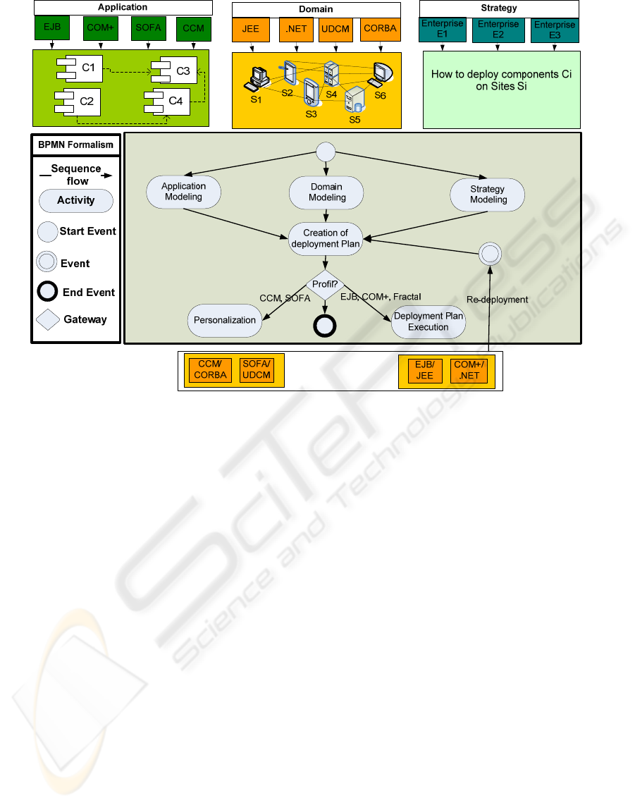
Figure 1: Architecture of UDeploy.
operated by models transformations. A model
transformation is defined by certain rules. These
rules can be described by using a transformation tool
such as Query View Transformation (QVT) or,
simply by implementing one’s own transformation
rules.
At deployment level, if we apply the MDA
approach, we identify clearly three different
metamodels: the application metamodel, the domain
metamodel and the deployment plan which are
common to most approaches studied. The quality of
metamodels provided in our framework entry
determines deployment success, safety (Parrish
et al., 2001) and automation. A success property
implies that the installed application works properly.
A safety property implies that existing applications
continue to work after the installation is applied. The
automation consists in making a deployment with
zero (or no) administrator.
The strategy modeling, the application modeling,
the domain modeling, the creation of deployment,
the personalization and the execution of the
deployment plan are described respectively in
section 4.2.3, 4.2.1, 4.2.2, 4.2.4, 4.2.5 and 4.2.6.
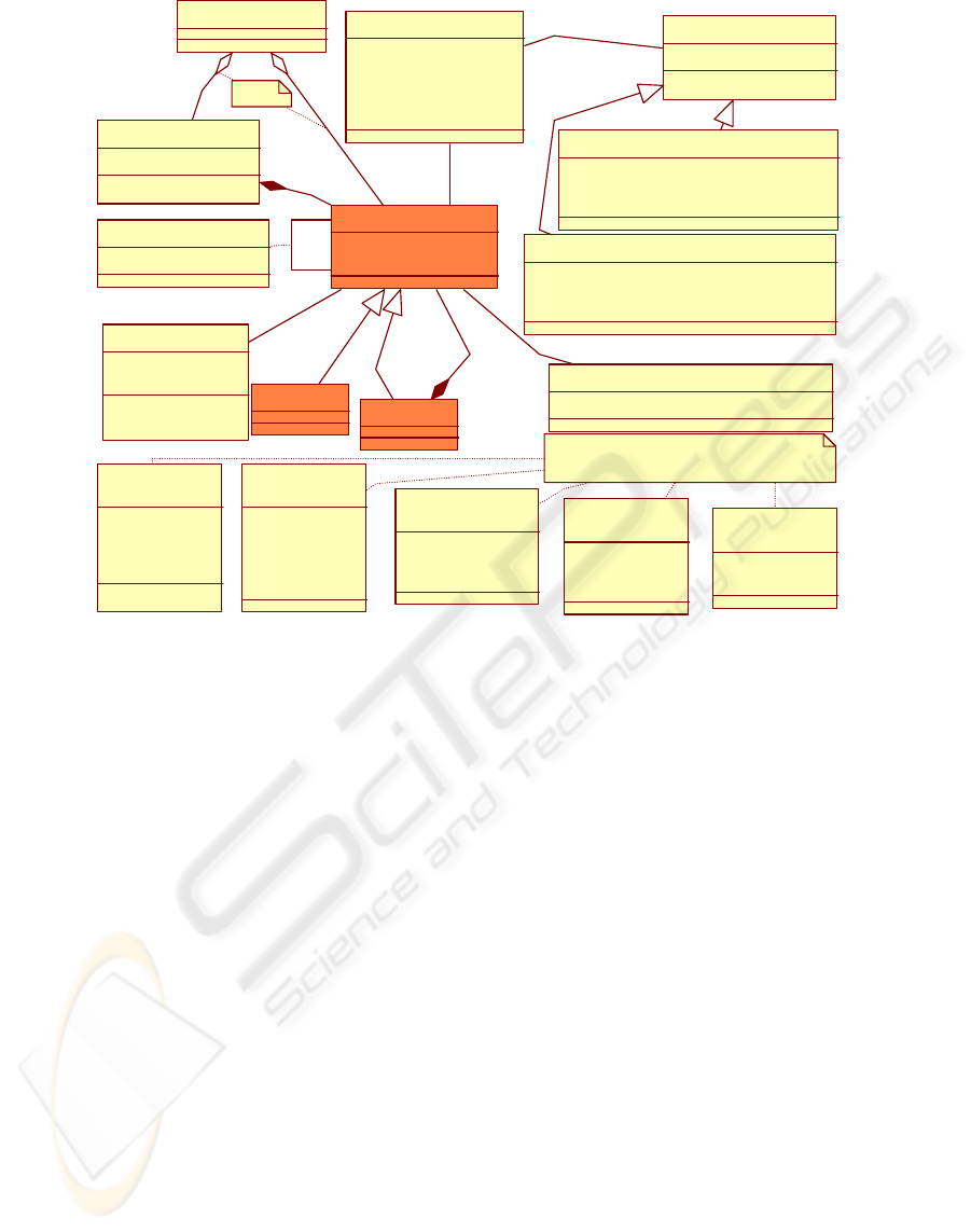
4.2.1 Application Modelling
Each application to be deployed is provided with a
descriptor described in a specific formalism. This
descriptor is called the specific application
descriptor. The specific application descriptor can
be more or less complete. Some specific application
descriptors describe basic information such as the
various components which compose an application
and, some others describe more elaborated
information such as the constraints in resources of
the components. The formalisms of specific
application descriptor are numerous; we
recommend an architecture description language
(ADL) to describe the software architectures. Our
ADL allows standardizing the application
description and, also allows the support of
components approaches which do not have strong
semantics of software architecture description. An
application descriptor will be an XML file that
conforms to our ADL and containing the following
information:
– the application producer,
– the list of the components which constitute the
application (immediate deployment) or the list of
some components which constitute the application
(progressive deployment),
– the compatibility between the various
implementations of components,
ICEIS 2010 - 12th International Conference on Enterprise Information Systems
318
Application
+ApplicationName: String
Component
+ComponentId: Integer
+ComponentName: String
Leaf
Composite
Requirem ent
+RequirementId: String
Sofwar eRequire ment
+SofwareRequirementType: SRType
+SofwareRequirementOperator: SROperator
+SofwareRequirementValue: String
MaterialRequirement
+MaterialRequirementType: MRType
+MaterialRequirementOperator: MROperator
+MaterialRequirementValue: Integer
SRType
<<enumeration>>
+OS
+DBMS
+WebServer
+ApplicationServ er
MRType
<<enumeration>>
+MassStorageGO
+RAMGO
+CPUType
0..*
1..*
+parent
+child
0..*
1..*
SROperator
<<enumeration>>
+Anterior
+Equals
+Posterior
MROpe ra t or
<<enumeration>>
+Equals
+Less
+Lessorequals
+Greater
+Greaterorequals
Others enumerations type can be defined.
Dependence
+DependenceType: TypeD
0..*
0..*
TypeD
<<enumeration>>
+Installation
+Activ ation
Properties
+PropertyType: String
+Value: StringSet
0..*
0..*
BusinessComponentUsesDomain
+ComponentConcept: String
0..*
0..*
Implementation
+Imp le me n t a t io nI d : I nt e ge r
+Version: Integer
+TypeAssembly: String
+A s s e mbly Na me : S t r ing
+LocalAdressPath: String
+Imp le me n t a t io ns
0..*
1
Requirements
0..*
0..*
DeploymentUnit
0..*
0..1
0..*
0..*
XOR
Figure 2: Application Metamodel.
– the description of each implementation
(component standard EJB, CCM, .NET, Fractal,
Sofa, Darwin, Kaola, component type),
– the description of the implementation code
(archive name, localization in repository),
– the programming language of the implementation
(Java, C ++),
– the human language (de, en, fr, es, pt, it),
– the strong dependencies or the implementations
assertions which cannot be resolved during the
deployment process; they express themselves by
imposing values of attribute for the compiler, the
OS, the processor, the runtime and the middleware.
– the low dependencies which can be resolved
during the deployment process; they express
how to install the compiler, the runtime, the
middleware and the files (library and executable)
indispensable for the execution of the
implementation,
– the localization of configuration files.
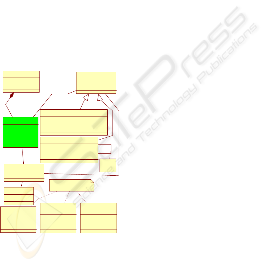
4.2.2 Domain Modelling
The deployment tool owes to know the available
resources in the domain. The domain represents all
the interconnected sites given to the administrator
for the deployment. The domain can be a domestic
network or a grid computer. The resources available
on the domain can be known by using several tools
developed within the grid computing infrastructures;
Sun Grid Engine (Engine, 2009), Globus (Globus,
2009) and Condor (Condor, 2009) are some
examples. These infrastructures allow the discovery
of the domain resources – or the available and
unavailable sites or nodes. Our domain description
model is based on an architecture description
language. The specific domain description will be an
XML file, conform to our ADL. The information on
sites and their available resources are collected by
questioning the Sun Grid Engine tool which is
previously installed on the domain. The domain
description is updated every time an event takes
place on the domain. The descriptor will contain the
following information:
– the domain name,
– the list of sites which compose the domain,
– the list of the available sites of the domain,
the description of the software resources for each
site – i.e. the compiler, the OS, the processor,
– the runtime, the middleware and the files (library
and executable),
DEFINING AN UNIFIED META MODELING ARCHITECTURE FOR DEPLOYMENT OF DISTRIBUTED
COMPONENTS-BASED SOFTWARE APPLICATIONS
319
– the description of the physical resources – i.e. the
number of processors, cache, clock speed, bus speed,
number of cores and memory,
– the list of components installed on each site
during previous deployment activities.
– the description of the network links (interconnect)
between sites,
– the description of the network link (interconnect)
performance (bandwidth, latency),
– the description of the Bridge. A Bridge (OMG,
2006b) exists between interconnects to describe an
indirect communication path between nodes. If a
connection is to be deployed between components
that are instantiated on nodes that are not directly
connected, therefore requiring bridging, the
connection's requirements must be satisfied by the
resources of each interconnect and bridge in
between.
Net workDoma in
+IdDomain: Integer
+DomainName: String
No d e
+NodeId: String
+NodeName: String
+MacAdress: String
Resource
+ResourceId: Integer
+ResourceName: String
Mat e rialResource
+MaterialResourceType: MRType
+MaterialResourceValue: Integer
+DynamicMaterialResourceValue: Integer
SoftwareResource
+SoftwareResourceType: SRType
+SoftwareResourceValue: String
+SoftwareResourceState: SRState
0..*
1..*
SRType
<<enumeration>>
+OS
+SpecificSoftware
+Component
MRType
<<enumeration>>
+RAMGO
+MassStorageGO
+CPUType
Others enumerations
type can be defined.
+provideresources
0..*
0..*
+new
+old
0..*
0..*
Version
SRState
<<enumeration>>
+Installed
+Uninstalled
Interconnect
+IdInterconnect: String
0..*
1..*
Bridge
+IdBridge: String
0..*
1..*
+resource
0..*
0..*
Figure 3: Domain Metamodel.
4.2.3 Strategy Modelling
The deployment strategies guide the creation of the
deployment plan. The deployment strategies allow
expressing the actions to be led to deploy a
component by assuring success and safety
properties.
4.2.4 Computing Plan (Creation of
Deployment Plan)
The deployment plan for an application A consists
of components C1 to Ci where i>= 1 and for a
domain D consisting of Sites S1 ti Sj where j> = 1 is
all valid placements (Ci, Sj). It is calculated from a
planner engine. This engine operates on a static
process which allows visualizing a state of the
system and the information remains motionless
during the plan computing or following a dynamic
process which allows visualizing the forecasts and to
supervise their realization; the information used is
variable during the computing plan. The planner
provides a graphical interface that is only at the PIM
(platform independent model) level. Thus, it
performs the calculations of inter-component
dependencies and verifies software and hardware
needs. Once the calculation ends, i.e. all constraints
are satisfied, the planner generates a deployment
plan independent of the hardware architecture and
the technology application to be deployed. The
deployment plan contains all data and all the
strategies needed to perform the deployment
properly.
4.2.5 Personalization
The deployment descriptor is an instantiation of the
deployment plan for a specific platform. It is
generally an XML file. At PIM level, we can
manipulate the concepts (component, site, resource,
constraint, dependency, and placement) and create
the instances. The persistence is processed under
Java for practical reasons. When the Java classes
were instanced, we use this data to generate the
deployment descriptor. However, the deployment
descriptor generated is conformed to specific
formalism. To assure the correspondence, we use
JDOM for the transcription of Java object in XML.
The deployment descriptor is not executed by
our framework UDeploy but by the target
middleware (Sofa runtime for SOFA profile and
StarCCM or OpenCCM for CCM profile).
4.2.6 Deployment Plan Execution
The components models as Fractal, EJB and COM+
do not offer a deployment descriptor which can be
executed afterward. Therefore, the calculus of the
deployment plan for this component model will be
executed by UDeploy_Executor. The execution of
the plan corresponds to: the starting up of servers,
the load of components in servers and the
establishment of the connections.
ICEIS 2010 - 12th International Conference on Enterprise Information Systems
320

5 PERSPECTIVE AND
CONCLUSIONS
In this paper we presented a generic framework for
deployment of component-based software
applications. The framework is composed of: the
application metamodel, the domain metamodel and
the deployment plan allowing to model, respectively
three main components of a deployment system (the
application, the domain and the deployment
descriptor). The framework is illustrate by
introducing a tool called Udeploy which ensures tree
main tasks: (i) it manages the planning process from
meta-information related to the application and the
infrastructure, (ii) it generates specific deployment
descriptors related to the application and the
environment (i.e. the machines connected to a
network where a software system is deployed), and
(iii) it executes a deployment plan.
In recent years, there have been many
development projects by academic works focusing
on a new generation of systems. These approaches
enhance technology transition. They have shown the
potential of using a model-driven approach such as
MDA. The defined models are based on expressive
and simple abstractions, so the application, the
location, the deployment process and its
orchestration can be built on top of that common
foundation. We hope that the deployment framework
we present is a valuable contribution to this new
generation of systems.
REFERENCES
Alliance, O., 2005. OSGi 4.0 release. Specification
available at http://www.osgi.org/.
Bures, T., Hnetynka, P., and Plasil, F., 2006. Sofa 2.0:
Balancing advanced features in a hierarchical
component model. In SERA, pages 40–48. IEEE
Computer Society.
Clements, P. C., 1996. A survey of architecture
description languages. In IWSSD ’96: Proceedings of
the 8th International Workshop on Software
Specification and Design, page 16, Washington, DC,
USA. IEEE Computer Society.
Condor, 2009. 7.4.1 release. Specification available at
http://www.cs.wisc.edu/condor/.
Dibo, M. and Belkhatir, N., 2009. Challenges and
perspectives in the deployment of distributed
components-based software. In ICEIS (3), pages 403–
406.
Dochez, J., 2009. Jsr 88: Java enterprise edition 5
deployment api specification. Available at
http://jcp.org/aboutJava/communityprocess/mrel/jsr08
8/index.html.
Edwards, G. T., Deng, G., Schmidt, D. C., Gokhale, A. S.,
and Natarajan, B., 2004. Model-driven configuration
and deployment of component middleware
publish/subscribe services. In GPCE, pages 337–360.
Engine, S. G., 2009. 6.2 release. Specification available at
http://www.sun.com/software/sge/.
Globus, 2009. 5.0.0 release. Specification available at
http://www.globus.org/.
Gustavo, A., Fabio, C., Harumi, K., and Vijay, M., 2004.
Web Services: Concepts, Architecture and
Applications.
Hall, R. S., Heimbigner, D., and Wolf, A. L., 1999. A
cooperative approach to support software deployment
using the software dock. In ICSE ’99: Proceedings of
the 21st international conference on Software
engineering, pages 174–183, New York, NY, USA.
ACM.
Merle, N. and Belkhatir, N., 2004. Une architecture
conceptuelle pour le déploiement d’applications à
grande échelle. In INFORSID, pages 461–476.
OMG, 2006a. Corba component model 4.0. Specification
available at http://www.omg.org/docs/formal/06-04-
01.pdf.
OMG, 2006b. Deployment and configuration of
component-based distributed application. Specification
available at http://www.omg.org.
OMG, T. O. M. G., 2005. Omg model driven architecture.
Available at http://www.omg.org.
OMG, T. O. M. G., 2007. Unified modeling language.
Available at http://www.omg.org.
Parrish, A., Dixon, B., and Cordes, D., 2001. A conceptual
foundation for component-based software deployment.
J. Syst. Softw., 57(3):193–200.
Szyperski, C., Gruntz, D., and Murer, S., 2002.
Component Software: Beyond Object-Oriented
Programming. Addison-Wesley Professional. 2nd
Edition, England.
Troelsen, A., 2008a. Chapter 1: The Philosophy of .NET,
volume Pro VB 2008 and the .NET 3.5 Platform.
APress.
Troelsen, A., 2008b. Chapter 15: Introducing .NET
Assemblies
, volume Pro VB 2008 and the .NET 3.5
Platform. APress.
DEFINING AN UNIFIED META MODELING ARCHITECTURE FOR DEPLOYMENT OF DISTRIBUTED
COMPONENTS-BASED SOFTWARE APPLICATIONS
321
