DVB-T MODULATOR IMPERFECTIONS
EVALUATION AND MEASUREMENT
Tomáš Kratochvíl, Radim Štukavec and Martin Slanina
Department of Radio Electronics, Brno University of Technology, Purkyňova 118, Brno, Czech Republic
Keywords: COFDM modulator, I/Q error, Amplitude Imbalance, Phase Error, Digital Video Broadcasting, DVB-T.
Abstract: The paper deals with simulation, evaluation and measurement of the DVB-T modulator imperfections.
Modulator imperfections’ and I/Q errors’ influence on the DVB-T signal and its spectrum and
I/Q constellation analysis are presented. Theoretical backgrounds of the Amplitude Imbalance, Phase Error
and Carrier Suppression effects are outlined in the paper. Then the practical results measured in the
laboratory environment are compared to the theoretical assumed impacts on Modulation Error Rate from
I/Q constellation and Bit Error Rates before and after Viterbi decoding in DVB-T signal decoding.
Commented results of the measurements are presented in the paper as well.
1 INTRODUCTION
The DVB-T (Digital Video Broadcasting –
Terrestrial) is already a standard (ETSI, 2004) and
technology for Digital TV distribution.
Technical characteristics make the DVB-T
system flexible to operate in a combination of
3 modulations (QPSK, 16-QAM, 64-QAM),
5 FEC rates (Forward Frror Correction),
4 Guard Intervals (1/32, 1/16, 1/8, 1/4),
3 modes of carriers - 2k (1705) or 8k (6817),
3 channel bandwidths (8, 7, 6) MHz.
Using different combinations of the above
parameters, a DVB-T network can be designed to
match the requirements of the network operator,
finding the balance between robustness and capacity.
Terrestrial transmission path is subject to
numerous impacts such as echoes and multipath
reception, AWGN (Additive White Gaussian Noise)
and Doppler shift in case of mobile reception. Apart
from this, the quality of the transmission link is also
determined by the DVB-T modulator and transmitter
parameters. A lower quality signal can be produced
caused by Crest factor limitation, intermodulation,
noise, I/Q errors and interferers (Fisher, 2008).
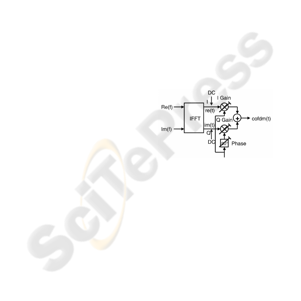
Figure 1: DVB-T modulator with I/Q errors
and imperfections (Fisher, 2008).
To avoid effects of the transmission link and
modulator imperfections, DVB-T uses COFDM
(Coded Orthogonal Frequency Division Multiplex).
DVB-T modulator (see Fig. 1) can exhibit
imperfections caused by different gains in I/Q
signals (Amplitude Imbalance), imprecise 90 degree
phase shift between I/Q signals (Phase Error) or
residual carrier in the frequency spectrum caused by
DC component in I/Q signals (Carrier Suppression).
Due to the channel estimation and carrier pilots all
these effects result in lower MER (Modulation Error
Rate) in dB from I/Q constellation and according
higher BER (Bit-Error Rate) (ETSI, 2001).
50
Kratochv
´
ıl T.,
ˇ
Stukavec R. and Slanina M. (2010).
DVB-T MODULATOR IMPERFECTIONS EVALUATION AND MEASUREMENT.
In Proceedings of the International Conference on Signal Processing and Multimedia Applications, pages 50-54
Copyright
c
SciTePress
2 EFFECTS OF THE I/Q ERRORS
The effects can be observed only at the center
carrier. The other carriers exhibit noise like
interference in the presence of any AI (Amplitude
Imbalance) and PE (Phase Error).
a) AI presence
b) PE presence
Figure 2: Determining SNR by vector diagrams in case of
I/Q errors (Fisher, 2008).
While determining the SNR (Signal-to-Noise
Ratio) with the AI and PE presence, equations
(1) to (4) apply:
AI
AI
aa
aa
SNR
−
=
−
+
=
2
21
21
,
(1)
[]
[]
[]
100/%
100/%2
log20
AI
AI
dBSNR
−
= ,
(2)
⎟
⎠
⎞
⎜
⎝
⎛
−
⎟
⎠
⎞
⎜
⎝
⎛
−
⋅=
2
90cos
2
90sin
2
2
ϕ
ϕ
a
a
SNR ,
(3)
[]
⎟
⎟
⎠
⎞
⎜
⎜
⎝
⎛
⎟
⎠
⎞
⎜
⎝
⎛
−=
2
90tanlog20
ϕ
dBSNR .
(4)
The disturbances in DVB-T caused by I/Q errors
can be explained by using vector diagrams (see
Fig. 2). Both mixers of the DVB-T modulator
operate with CS (Carrier Suppression) and SSB
(Single Sideband Modulation) technique. Using this
technique, two sideband vectors are added and two
sideband vectors are subtracted (cancelled band).
If the AI or PE exists, it means that the upper
or lower sideband is no longer canceled completely
and leaves an interference component.
It is clear that all the subcarriers are subject to
noise like interference, with the exception of the
center carrier. This can be shown in the spectrum if
the lower carrier band is switched off. Hence, if the
I/Q modulator is adjusted to produce AI or PE, an
evident crosstalk from the upper to the lower
sideband is clearly apparent.
A DC component in re(t) or im(t) signals after
the IFFT leads to a residual carrier in the I or Q
branch or in both of them. Apart from the
corresponding amplitude, the residual carrier also
exhibits phase angle. A residual carrier at DVB-T
modulator shifts the constellation diagram out of the
centre in I or Q signal direction. The diagram
remains undistorted and it can be verified only at the
central carrier. Insufficient carrier suppression
appears in the centre of the constellation diagram.
Some works related to this paper were published
also by (Bucholtz, 2000) and (Palipana, 2005, 2007).
3 BEHIND THE I/Q ERRORS
The Viterbi decoder can correct bit errors depending
on the code rate selected in the convolutional
encoder. The approximation condition for the QEF
(Quasi-Error Free) reception, which corresponds
to one error per hour, is defined as BER after Viterbi
decoding equal to 2.10
-4
or less. This is the limit
at which the subsequent Reed-Solomon decoder still
delivers an output BER after RS decoding of 1.10
-11
or less. This condition almost corresponds to the
“fall of the cliff” and “blockiness” appearing in the
picture. Slightly more noise or interference suffices
for the DTV transmission to break down.
From the SNR or MER in dB, the BER before
Viterbi decoding (channel BER) can be determined
or at least estimated. Theoretical minimal SNR for
QEF reception depends on the convolutional code
rate, type of the COFDM inner modulation and the
type of the transmission channel - Gaussian, Ricean
or Rayleigh (ETSI, 2001, 2004).
Theoretical CNR (Carrier-to-Noise Ratio) value
for the DVB-T signal transmission analyzed in this
paper (64-QAM, 8k mode, 2/3 code rate, 1/8 guard
interval, non-hierarchical modulation) is equal
to 16.5 dB in the AWGN (Gaussian) channel
for stationary reception. Practical CNR value
is about 18 to 20 dB (Fisher, 2008).
DVB-T MODULATOR IMPERFECTIONS EVALUATION AND MEASUREMENT
51
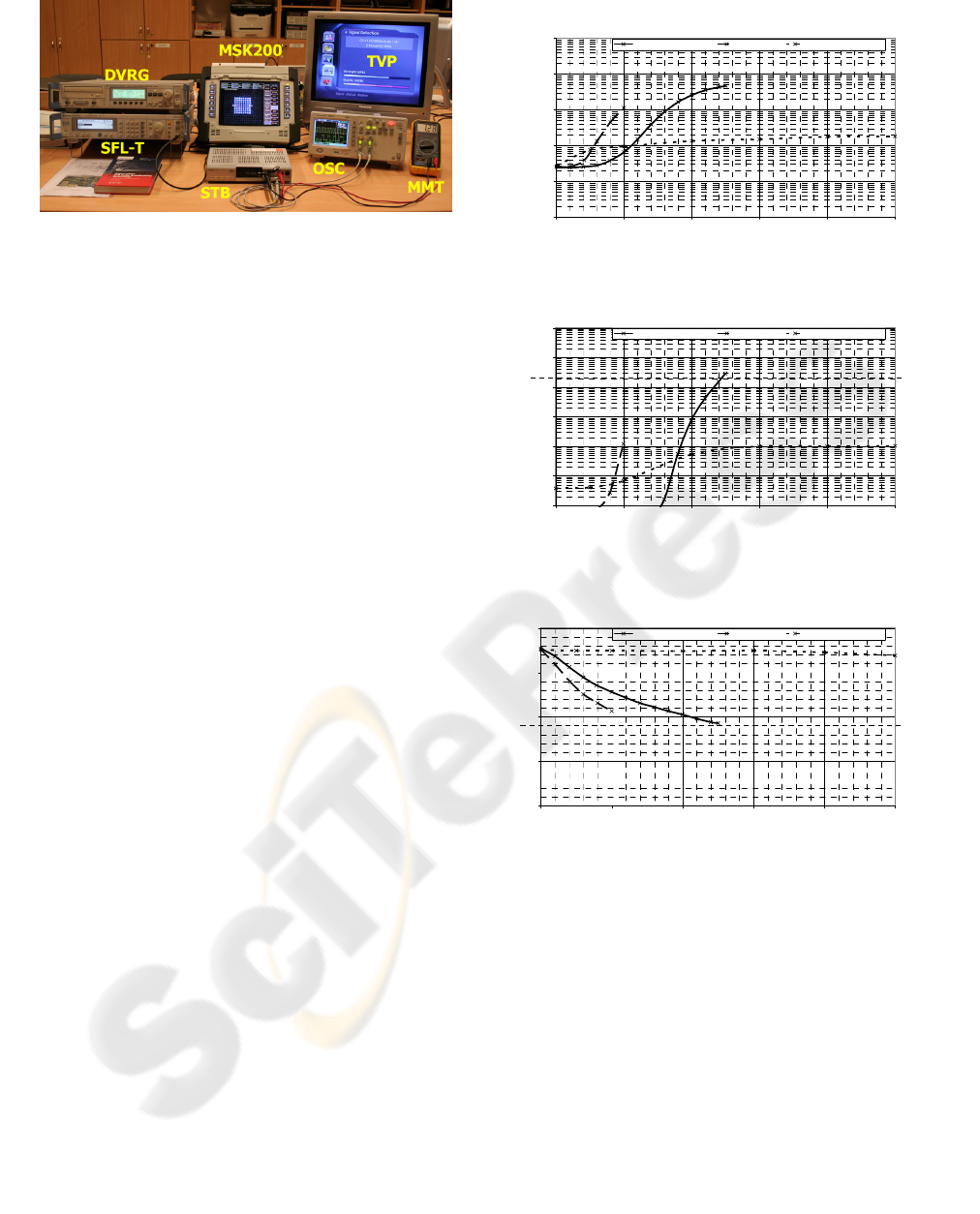
Figure 3: Laboratory workplace for the DVB-T
measurements and transmission link.
4 DVB TRANSMISSION SYSTEM
Laboratory workplace for the DVB-T measurements
(see Fig. 3) has been used for the evaluation of I/Q
errors on MER. The devices are:
SFL-T R&S DVB-T test transmitter,
DVRG R&S MPEG-2 TS generator,
MSK200 Kathrein DVB-T test receiver,
STB Humax F3 FOX-T commercial set-top box
adapted with tuner IF outputs and transport
stream MPEG-2 TS data output,
OSC Agilent digital storage oscilloscope,
MMT Metex multimeter,
TVP Panasonic TV set.
The DVB-T system transmission parameters were
set to the European most common type of DTV
broadcasting. These parameters are the most
characteristic for large DVB-T SFN networks:
RF level 60 dBuV (medium sensitivity),
8 MHz channel (bandwidth 7.608 MHz),
64-QAM modulation (TS 19.90588 Mbit/s),
8k mode – 6817 subcarriers (fixed reception),
2/3 convolutional code rate (robust code),
1/4 Guard Interval (large size SFN),
non-hierarchical modulation (one TS).
For the Amplitude Imbalance AI, Phase Error PE
and Carrier Suppression CS influence on MER,
BER
1
(before Viterbi) and BER
2
(after Viterbi)
evaluation, the DVB-T modulator and test
transmitter parameters were set in these intervals:
AI - (0 .. 25% with step of 2%),
PE - (0..10
o
with step of 1 degree),
CS - (0 .. 50% with step of 5%).
BER before Viterbi vs. I/Q errors
1,0E-05
1,0E-04
1,0E-03
1,0E-02
1,0E-01
1,0E+00
0 1020304050
AI [%], PE [deg], CS [%]
BER
before Viterbi
[-]
Amplitude Imbalance Phase Error Carrier Suppression
a) BER
before Viterbi
= f (AI, PE, CS)
BER after Viterbi vs. I/Q errors
1,0E-08
1,0E-07
1,0E-06
1,0E-05
1,0E-04
1,0E-03
1,0E-02
0 1020304050
AI [%], PE [deg], CS [%]
BER
after Viterbi
[-]
Amplitude Imbalance Phase Error Carrier Suppression
QEF
b) BER
after Viterbi
= f (AI, PE, CS)
MER vs. I/Q errors
0,0
10,0
20,0
30,0
40,0
0 1020304050
AI [%], PE [deg], CS [%]
MER
[dB]
Amplitude Imbalance Phase Error Carrier Suppression
MIN
c) MER = f (AI, PE, CS)
Figure 4: DVB-T modulator imperfections and I/Q errors
measurements (independent AI, PE and CS).
5 MEASUREMENT RESULTS
The results of the BER before Viterbi, BER after
Viterbi and MER measurements as the functions of
the AI, PE, CS are shown in Fig. 3. The “QEF”
symbol in Fig. 4b) indicates the situation where BER
after Viterbi decoding is equal to 2.10
-4
. This is the
formerly defined condition of practically error-free
signals at the input of the MPEG-2 TS
demultiplexer. The “MIN” symbol in Fig. 4c)
indicates the situation where the DVB-T with
SIGMAP 2010 - International Conference on Signal Processing and Multimedia Applications
52
modulation 64-QAM, convolutional code rate 2/3
and non-hierarchical modulation has the minimal
required CNR equal to approx. 18 dB. This is the
reference value of possible DVB-T in a no-
interference reception.
The main impact on I/Q errors on BER and MER
is caused by Amplitude Imbalance. Decrease of
10 dB in MER is caused by the AI of approx. 10 %
between I/Q signals. It is evident that the most
serious impact on I/Q errors has the Phase Error.
Decrease of 10 dB in MER is caused by PE of
approx. 6 degrees between I/Q signals. There is
no serious impact and influence of Carrier
Suppression on I/Q errors (see Fig. 5, all carriers
displayed).
Figure 5: I/Q constellation of the DVB-T, 64-QAM, 8k
mode and in case of CS = 50% presence (CS error visible
in the centre of the diagram).
A really interesting evaluation could be the
dependence of AI and PE simultaneously on MER as
it is shown in the Fig. 6. With the AI higher than
approx. 20 % and PE higher than approx. 8 degrees,
the DVB-T signal is not available for decoding.
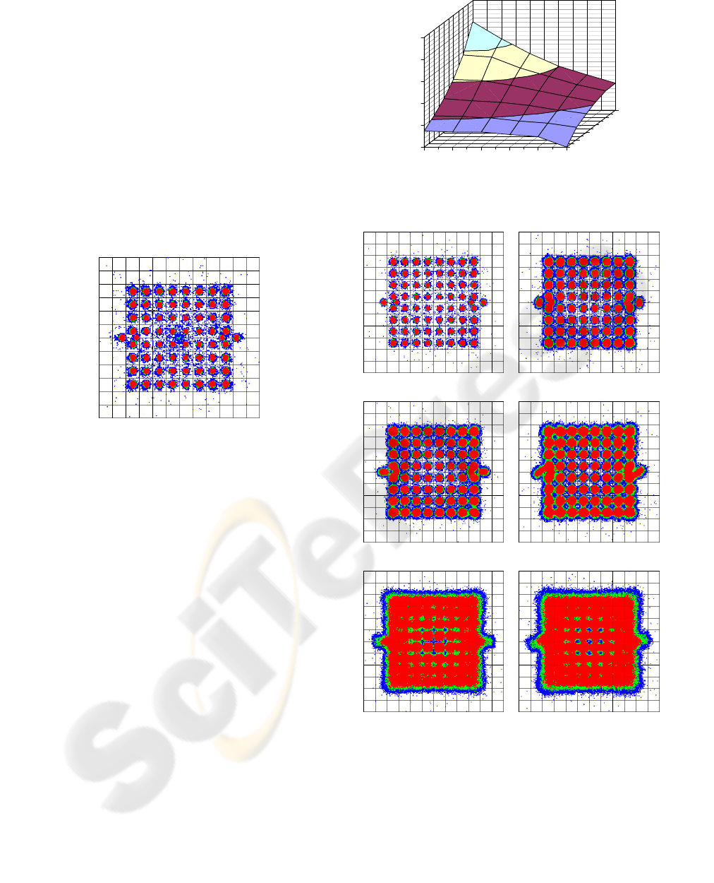
In Fig. 7, I/Q constellation diagrams of the
DVB-T with 64-QAM, 8k mode are shown. In the
individual pictures the simultaneous influence of AI
and PE on the I/Q constellation is displayed. I/Q
errors of the modulator partially affect all the
carriers as noise-like disturbance (typical shape
of clouds) and can only be identified by observing
the central carrier (again no. 3408 in 8k mode).
6 CONCLUSIONS
From the measured results it is easy to see that both
the AI and PE lead to lower MER from I/Q
constellation analysis (see Fig. 7) and noise like
crosstalk in the spectrum (see Fig. 8 and Fig. 9).
15,0
20,0
25,0
30,0
35,0
40,0
MER [dB]
0246810
0
10
20
PE [deg]
AI [% ]
Figure 6: DVB-T modulator imperfections and I/Q errors
measurements (simultaneous AI and PE).
a) AI = 0%, PE = 0
o
,
MER = 35.2 dB
b) AI = 0%, PE = 5
o
,
MER = 26.3 dB,
c) AI = 10%, PE = 0
o
,
MER = 25.6 dB
d) AI = 10%, PE = 5
o
,
MER = 23.5 dB
e) AI = 20%, PE = 0
o
,
MER = 20.5 dB,
f) AI = 20%, PE = 5
o
,
MER = 19.7 dB,
Figure 7: I/Q constellation of the DVB-T with 64-QAM,
8k mode and in case of AI and PE presence (DVB-T
channel correction and all pilots ON).
DVB-T MODULATOR IMPERFECTIONS EVALUATION AND MEASUREMENT
53
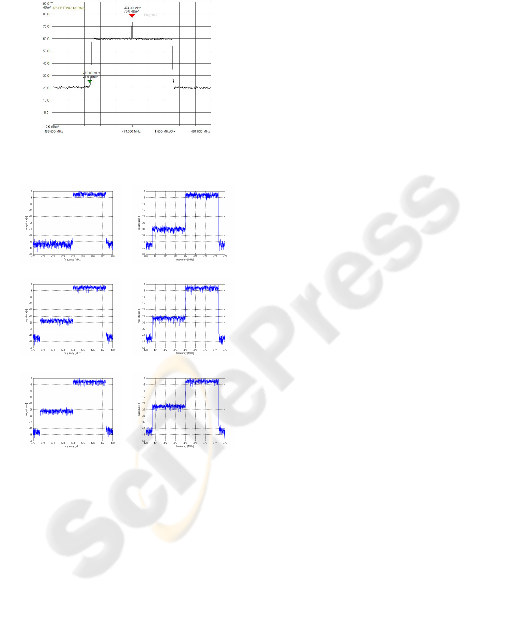
Figure 8: DVB-T spectrum without suppressed carrier,
C21 (470 – 478) MHz, 8k mode, CS = 50% (CS error
visible at central carrier, 474 MHz).
a) AI = 0%, PE = 0
o
b) AI = 0%, PE = 5
o
c) AI = 10%, PE = 0
o
d) AI = 10%, PE = 5
o
e) AI = 20%, PE = 0
o
f) AI = 20%, PE = 5
o
Figure 9: Simulated spectrum of the DVB-T with 64-
QAM, 8k mode and in case of AI and PE presence (lower
band carriers 0 - 3407 were set to zero to illustrate the
crosstalk).
The effect can be described by means of simple
trigonometric operations which can be derived from
the vector diagram of the signal and noise. In the
case of AI, the opposite vectors of I/Q signals with
noise are not cancelled completely and it results
in a noise vector causing crosstalk from the upper
band to lower frequency band.
A phase error will result in a noise vector with
the length determined by the vector parallelogram.
In both cases the actual useful signal amplitude
decreases by the same amount by which the
crosstalk increases.
In the practical and commercial DVB-T
modulator implementations, usually AI less than 5%
and PE less than 0.5 degree is the aim of the design
and it is verified only very close to the center carrier
(no. 3408 in case of the DVB-T and COFDM 8k
mode) and adjacent carriers.
ACKNOWLEDGEMENTS
The paper was supported by the Research program
of the Brno University of Technology
no. MSM0021630513, “Electronic Communication
Systems and New Generation Technology
(ELKOM)” and the research grant projects of the
Czech Science Foundation GACR no. 102/08/P295
“Analysis and Simulation of the Transmission
Distortions of the Digital Television DVB-T/H“
and no. P102/10/1320 “Research and Modeling
of Advanced Methods of Image Quality Evaluation
(DEIMOS)”.
REFERENCES
Fisher, W. Digital Video Broadcasting, The family
of international standards for digital television
(2
nd
edition). Berlin: Springer Verlag, 2008.
ISBN 978-3-540-76357-4.
ETSI EN 300 744 V1.4.1 (2004-11). European Standard.
Digital Video Broadcasting (DVB); Framing
structure, channel coding and modulation for DTT.
EBU, 2004.
ETSI TR 101 290 V1.2.1 (2001-05). Technical report.
Digital Video Broadcasting (DVB); Measurement
guidelines for DVB systems. EBU, 2001.
Buchholz, M., Schuchert, A., Hasholzner, R. Effects of
tuner IQ imbalance on multicarrier-modulation
systems. Proceedings of the 2000 Third IEEE
International Caracas Conference on Devices, Circuits
and Systems, 2000 , pp. T65/1 - T65/6
Palipana, R.B., Chung, K.S. The effects of receiver
impairments in terrestrial digital video broadcasting.
APCC2003, Asia-Pacific Conference on
Communications, 2003, pp. 1143 - 1146
Palipana, R.B., Chung, K.S. Pilot based correction of iq
cross-talk in the presence of a frequency offset.
APCC2007, Asia-Pacific Conference on
Communications, 2007, pp. 69 – 72
SIGMAP 2010 - International Conference on Signal Processing and Multimedia Applications
54
