
AN AUTOMATED MODEL-DRIVEN TESTING FRAMEWORK
For Model-Driven Development and Software Product Lines
Beatriz Pérez Lamancha
Software Testing Center, Republic University, Montevideo, Uruguay
Macario Polo Usaola, Mario Piattini
ALARCOS Research Group, Castilla – La Mancha University, Ciudad Real, Spain
Keywords: MDE, SPL, Model-driven testing, UML, UML Testing Profile, QVT, MOF2Text.
Abstract: This work presents an automated testing framework that can be applied to Model-Driven Development and
Software Product Line development. The framework uses standards metamodels such as UML, UML
Testing Profile and standards transformation languages such as Query/View/Transformation or MOF2Text.
Test cases are automatically generated from UML sequence diagrams that represent the functionality to test.
1 INTRODUCTION
Model-based Testing (MBT) provides a technique
for the automatic generation of test cases using
models extracted from software artifacts (Dalai, Jain
et al. 1999).
Model-Driven Engineering (MDE) and Software
Product Lines (SPL) are new software development
paradigms. In MDE, models are transformed to
obtain the product code, while in SPL, several
products share the same base structure. In both
approaches, automation is one of the main
characteristics -- in MDE the code generation is
automated from models while in SPL each product
is automatically generated from a base structure. In
addition, there are many works that merge MDE and
SPL(Deelstra, Sinnema et al. 2003; Czarnecki,
Antkiewicz et al. 2005; Trujillo, Batory et al. 2007).
The aim is to maximize reuse and minimize time
to market, without losing the final product quality.
In SPL, the products in the line shared common
functionality. If a defect is present in one of the
common parts, that defect is translated to each
product in the SPL. The final product quality
directly depends on the quality of each of the parts.
In this context, the goal is to reduce the test time
without affecting the product quality. In the case of
MDE, a change in one model involves rebuilding the
models and code automatically, and it takes little
time to generate the new code. However, from the
testing point of view, ensuring that this change does
not introduce defects entails retesting everything
again. If the tests are manually executed, the cost of
testing increases. The same applies to LPS. Testing
the common things is not sufficient; the integration
of each product must also be tested. For this reason,
the automation of tests from models in these two
paradigms is essential.
This work presents an automated framework for
model-driven testing that can be applied in MDE
and SPL development. The main characteristics of
the framework are:
Standardized: The framework is based on
Object Management Group (OMG) standards,
where possible. The standards used are UML,
UML Testing Profile as metamodels and
Query/View/Transformation (QVT) and
MOF2Text as transformation languages.
Model-driven Test Case Scenario Generation:
The framework generates the test cases at the
functional testing level (which can be extended
to other testing levels), the test case scenarios are
automatically generated from design models and
evolve with the product until test code
generation. Design models represent the system
behaviour using UML sequence diagrams.
Framework Implementation using Existing
Tools: No tools are developed to develop the
framework; existing market tools that conform to
the standards can be used. The requisite is that
112
Pérez Lamancha B., Polo Usaola M. and Piattini Velthius M. (2010).
AN AUTOMATED MODEL-DRIVEN TESTING FRAMEWORK - For Model-Driven Development and Software Product Lines.
In Proceedings of the Fifth International Conference on Evaluation of Novel Approaches to Software Engineering, pages 112-121
DOI: 10.5220/0002999901120121
Copyright
c
SciTePress

the modelling tool can be integrated with the
tools that produces the transformations.
This paper is organized as follows: Section 2
introduces the main concepts used in the article and
outlines the Lottery SPL; this SPL is used as the
running example. Section 3 outlines the entire
model-driven testing framework. Section 4 describes
the activities for the framework in MDE
development. Section 5 describes the activities in
SPL development. Section 6 summarizes related
works. Finally, Section 7 draws some conclusions
and presents future lines of work.
2 BACKGROUND
Model-Driven Engineering (MDE) considers
models as first-order citizens for software
development, maintenance and evolution through
model transformation (Mens and Van Corp 2006). In
addition to independence between models, Model-
Driven Architecture (MDA, (OMG 2003)) clearly
separates business complexity from implementation
details by defining several software models at
different abstraction levels. MDA defines three
viewpoints of a system: (i) the Computation
Independent Model (CIM), which focuses on the
context and requirements of the system without
considering its structure or processing, (ii) the
Platform Independent Model (PIM), which focuses
on the operational capabilities of a system outside
the context of a specific platform, and (iii) the
Platform Specific Model (PSM), which includes
details relating to the system for a specific platform.
The UML 2.0 Testing Profile (UML-TP) defines
a language for designing, visualizing, specifying,
analyzing, constructing and documenting the
artifacts of test systems. It extends UML 2.0 with
test specific concepts for testing, grouping them into
test architecture, test data, test behaviour and test
time. As a profile, UML-TP seamlessly integrates
into UML. It is based on the UML 2.0 specification
and is defined using the metamodeling approach of
UML(OMG 2005). The test architecture in UML-TP
is the set of concepts to specify the structural aspects
of a test situation (Baker, Dai et al. 2007). It includes
TestContext, which contains the test cases (as
operations) and whose composite structure defines
the test configuration. The test behaviour specifies
the actions and evaluations necessary to evaluate the
test objective, which describes what should be
tested. The test case behaviour is described using the
Behavior concept and can be shown using UML
interaction diagrams, state machines and activity
diagrams. The TestCase specifies one case to test the
system, including what to test it with, the required
input, result and initial conditions. It is a complete
technical specification of how a set of
TestComponents interacts with an SUT to realize a
TestObjective and return a Verdict value (OMG
2005). This work focuses on test cases, whose
behavior is represented by UML sequence diagrams.
Software Product Lines (SPL) are suitable for
development with Model Driven principles: an SPL
is a set of software-intensive systems sharing a
common, managed set of features which satisfy the
specific needs of a particular market segment or
mission and which are developed from a common
set of core assets in a prescribed way(Clements and
Northrop 2001). Therefore, products in a line share a
set of characteristics (commonalities) and differ in a
number of variation points, which represent the
variabilities of the products. Software construction
in SPL contexts involves two levels: (1) Domain
Engineering, referred to the development of the
common features and to the identification of the
variation points; (2) Product Engineering, where
each concrete product is built, what leads to the
inclusion of the commonalities in the products, and
the corresponding adaptation of the variation points.
Thus, the preservation of traceability among
software artifacts is an essential task, both from
Domain to Product engineering, as well as among
the different abstraction levels of each engineering
level.
The way in which variability is managed in SPL
is critical in SPL development. In this work, the
proposal by Pohl et al. (Pohl, Böckle et al. 2005) is
used to manage the variability, defined in their
Orthogonal Variability Model (OVM). In OVM,
variability information is saved in a separate model
containing data about variation points and variants (a
variation point may involve several variants in, for
example, several products). OVM allows the
representation of dependencies between variation
points and variable elements, as well as associations
among variation point and variants with other
software development models (i.e., design artifacts,
components, etc.). Associations between variants
may be requires_V_V and excludes_V_V, depending
on whether they denote that a variation requires or
excludes another variation. In the same way,
associations between a variation and a variation
point may be requires_V_VP or excludes_V_VP,
also to denote whether a variation requires or
excludes the corresponding variation point.
The variants may be related to artifacts of an
arbitrary granularity. Since variants may be related
AN AUTOMATED MODEL-DRIVEN TESTING FRAMEWORK - For Model-Driven Development and Software
Product Lines
113
to any type of software artifact (and in the proposal
the software artifacts are described using a UML
metamodel), to obtain the best fit in this integration,
OVM was translated into an UML Profile. With this
solution, OVM is managed and manipulated as a
part (actually, an extension) of UML 2.0 More
details about the defined OVM profile can be found
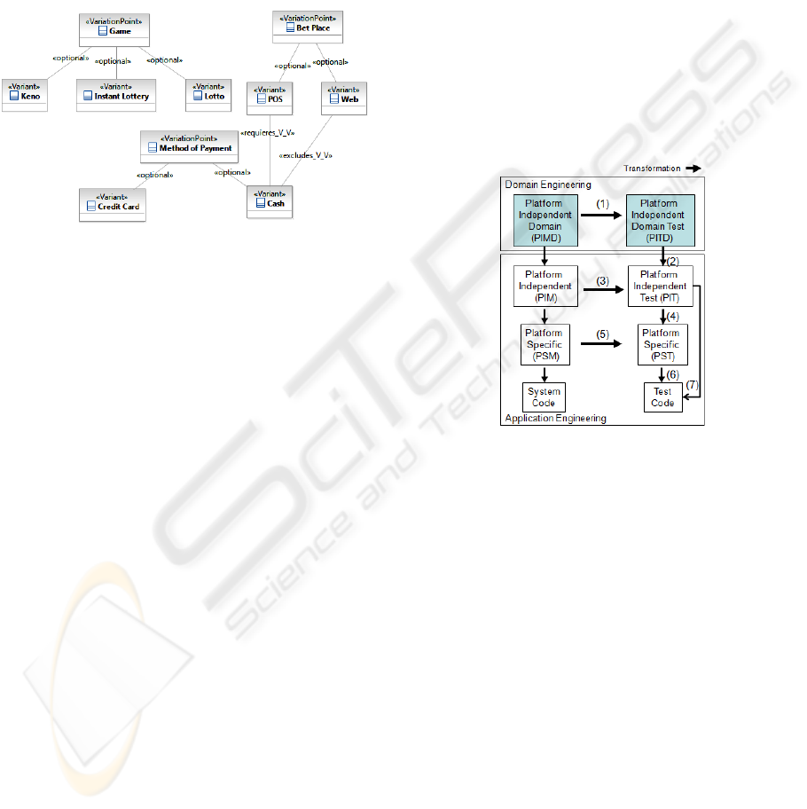
in (Pérez Lamancha, Polo Usaola et al. 2009). Figure
1 shows the OVM model for the Lottery SPL used
as an example in this paper.
Figure 1: OVM model for Lottery SPL.
Lottery SPL manages the bets and payments for
different lottery-type games. The types of games
considered are:
Instant Lottery: played using a scratch card,
whose participants rub or scratch it to remove a
coating that conceals one or more playing game
pieces and related cash prize amounts. Generally,
instant lottery tickets are printed on heavy paper
or cardboard.
Lotto: played by selecting a predetermined
quantity of numbers in a range: depending on the
right numbers, the prize is greater or lower. For
example, one chooses six numbers from 1 to 49.
Keno: basically played in the same manner,
although it differs from “Lotto” games in that (i)
the population of playing game pieces is even
larger, e. g., integers from 1 to 80; (ii)
participants can choose the quantity of numbers
that they want to match; and (iii) the number of
winning game numbers, e. g., twenty, is larger
than the number of a participant's playing
numbers, e. g. two to ten. One example of the
Keno type is Bingo.
This SPL has several variation points, but for
purposes of illustration, this paper only analyzes the
variation points in Figure 1:
Game: can be Instant Lottery, Lotto or Keno
Bet Place: The game can be played at a Point of
Sale (POS) or through a web page.
Method of Payment: Can be cash or credit card.
3 MODEL-DRIVEN TESTING
FRAMEWORK
Figure 2 shows a global overview of the framework,
which is divided horizontally into Domain
Engineering and Application Engineering. In
Domain Engineering, the SPL core assets are
modelled. In Application Engineering, each product
is modelled; it can be derived from the SPL or can
be one single product developed following MDE
software development.
The framework is also divided vertically into
Design models (left) and Testing models (right). In
Domain Engineering, a test model is generated for
SPL core assets. In Application Engineering, the
models follow the MDA levels, and are based on the
idea from Dai (Dai 2004).
Figure 2: Testing framework overview.
The arrows in Figure 2 represent transformations
between models. The objective is to automate the
test model from design models that represent the
functionalities to test the model using model
transformation. To develop the entire framework,
the following decisions were taken:
Tool to Support the Framework: This decision
is crucial for the development of the framework.
We could develop a tool to support the
framework or could use tools already available
on the market. The aim of our proposal is to
automate testing in MDE and SPL. Therefore, a
tool built by us must consider modelling
elements for both development paradigms. In
this case, operators using our approach must use
our tool to model the line or product to obtain the
test cases. However, these models must also be
used for code generation (due to the fact that the
development follows an MDE approach), for
which specific tools exist. It seems unrealistic to
ENASE 2010 - International Conference on Evaluation of Novel Approaches to Software Engineering
114
think that developers will do the double job of
modelling, with its associated maintenance cost.
Therefore, our proposal must be adapted to the
way it is modelled and developed in MDE and
SPL. Thus, we decided to develop the framework
using existing tools on the market, which brought
about another problem: the integration of
existing tools to achieve the complete
implementation of the framework.
Design Metamodel: We can develop our own
metamodels or use existing ones. We decided to
use existing metamodels and specifically used
UML 2.0 (OMG 2007) due to its being the most
widely used metamodel to design software
products and the fact that there are several tools
to support it in the MDE environment.
Testing Metamodel: Again, we could develop
our metamodel or use an existing one. We
decided to use the UML 2.0 Testing Profile.
Standardized Approach: Since UML 2.0 is
used as the design metamodel and the UML
Testing Profile as the testing metamodel, both
OMG standards and those using commercial
tools are more likely to be compatible with
standardized approaches. We decided to use
standards whenever possible for the construction
of the framework.
Variability Metamodel: Unfortunately, there is
no defined standard for defining metamodel
variability in product line development. Several
metamodels to represent variability exist. This
work uses the Orthogonal variability model
(OVM, (Pohl, Böckle et al. 2005) ) (see Section
2).
Model to Model Transformation Language: A
model transformation is the process of
converting one model to another model in the
same system (Miller and Mukerji 2003). The
most important elements in a transformation are:
(1) source model and target model, (2) source
metamodel and target metamodel and (3) the
definition of the transformation. A model
transformation language is a language that takes
a model as input and, according to a set of rules,
produces an output model. Using transformations
between models, arrows 1,2,3,4 and 5 in Figure 2
can be solved. The OMG standard for model
transformation in the MDA context is the Query-
View-Transformation language (QVT, (OMG
2007)), which depends on MOF (Meta-Object
Facility, (OMG 2002)) and OCL 2.0 (OMG
2006) specifications.
Model to Text Transformation Language:
Arrows 6 and 7 in Figure 2 require the
transformation from model to test code (for
example, this can be the JUnit test code). The
OMG standard to translate a model to various
text artifacts such as code is the MOF Model to
Text standard (MOF2Text, (OMG 2008)).
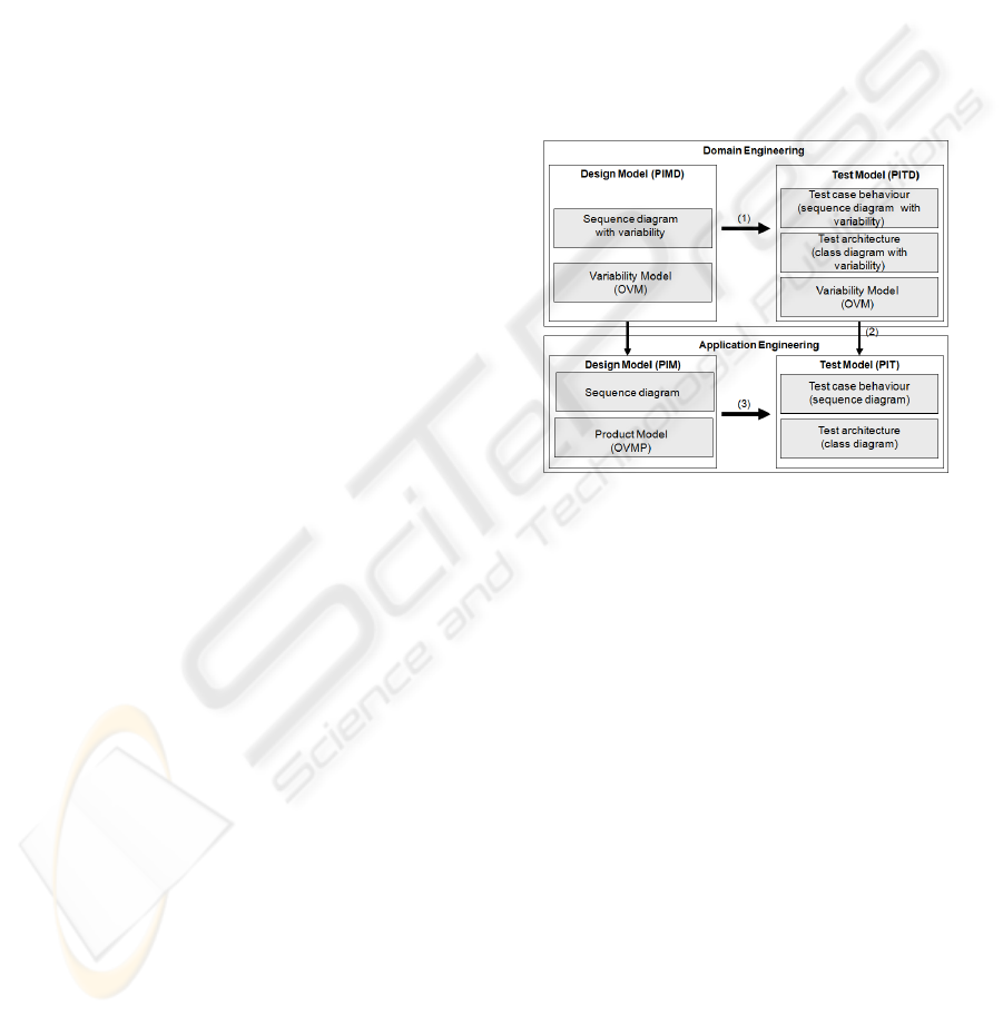
3.1 Models in Domain Engineering
As discussed above, the framework uses UML as its
metamodel. UML has several diagrams to represent
the static and dynamic aspects in software
development. Figure 3 shows the UML diagrams
used in the framework. This can be extended to
other UML diagrams, but for the moment, the
framework supports the models defined in Figure 3.
Figure 3: Framework models at PIM level.
In Domain Engineering, product line design
models are automatically transformed into test
models following UML-TP (arrow 1). The
variability is traced from the design to the test
models. In the transformation, the following models
are used as source models:
Sequence Diagrams with Variability: which
describe use case scenarios. As a metamodel, this
kind of model uses extended UML interactions
with stereotypes to represent variability. The
extension represents each variation point as a
CombinedFragment stereotyped with a Variation
Point. Each variant is an InteractionOperand
stereotyped as a Variant (see Section 5).
Variability Model: this model represents the
variability in the SPL. The definition of a UML
profile to integrate OVM into UML is required.
These models are transformed, using the QVT
language, into the following target UML-TP
elements (arrow 1 in Figure 3):
Test Case Behaviour: describes the test case
behaviour that tests the source sequence diagram.
As a metamodel, this model uses the same
AN AUTOMATED MODEL-DRIVEN TESTING FRAMEWORK - For Model-Driven Development and Software
Product Lines
115

variability extension for UML interactions as the
source sequence diagram (see Section 5).
Variability Model: this is the source variability
model, but in the transformation, the variability
model is augmented by traces to the test artifacts.
Test Architecture: this model is a class diagram
that uses an extension for the UML Testing
Profile as its metamodel. This extension applies
the stereotypes Variation Point and Variant to the
variable elements in the test architecture (see
Section 5).
3.2 Models in Application Engineering
Application Engineering takes into account both the
MDE and SPL development. In the case of SPL, at
this level the variability must be resolved. Thus, this
level contains both the test cases refined from the
domain engineering for a product (which involves
resolving the variability corresponding to arrow 2),
as well as the test cases for the functionalities added
only for that product. For the new functionalities, the
test cases are automatically generated using QVT
from sequence diagrams (arrow 3). The
transformation generates the test case behaviour as
another sequence diagram and a class diagram
representing the test architecture. Both models
conform to the UML Testing Profile.
3.3 Framework Implementation
The implementation of the framework requires the
selection of a modelling tool from those on the
market and defining the tools that perform the
transformations between the models and from model
to code.
The transformations between the models use QVT
language, which requires having a tool that
implements the standard. medini QVT implements
OMG's QVT Relations specification in a QVT
engine. We used it to develop and execute the QVT
transformations.
The integrated developed framework Eclipse makes
it possible to use modelling tools in an integrated
way, using extensions in the form of plug-ins. A
medini QVT plug-in for Eclipse currently exists and
is used for the model transformation in our proposal.
Other Eclipse plug-ins are used to perform the
modelling tasks:
Eclipse Modelling Framework (EMF): this is a
modelling framework that allows the
development of metamodels and models, from a
model specification described in XMI, provides
tools and runtime support to produce a set of
Java classes for the model, along with a set of
adapter classes that enable viewing and
command-based editing of the model, and a basic
editor.
UML2: this is an EMF-based implementation of
the UML 2.0 OMG metamodel for the Eclipse
platform.
UML2 Tools: A Graphical Modelling
Framework editor for manipulating UML
models.
Using these integrated tools for transformations
between models requires that the input models for
transformations be XMI (which is the default
serialized form of EMF) in eclipse UML2 format.
Therefore, the selected tool for the graphical
modeling must support the import and export of
models in the UML2 format through XMI.
There are many tools available that export UML
models to the UML2 format through XMI, but few
import the UM2 format.
In our case, since the behavior of the test case is
automatically generated as a sequence diagram, it is
crucial that the modelling tool be able to import the
transformed models and visualize them.
The tool selected is the IBM Rational Software
Modeler. This tool graphically represents the
sequence diagrams and exports them to UML2
through XMI. This XMI is the input for the QVT
transformation, which returns the XMI
corresponding to the Test Model. This output XMI is
imported to the IBM Rational Software Modeler,
which shows the graphical representation for the test
cases. The models shown in this paper were obtained
using this tool.
4 TESTING FRAMEWORK
FOR MDE
The preceding sections have presented the decisions
taken in the process of defining the framework,
and the metamodels and models defined for it.
This section describes the activities necessary to
implement the testing framework in MDE
development.
Figure shows the process for generating the test
model for MDE development. The activities at the
PIM level are:
P1-Add New Functionality for the Product: in
this activity, the functionality for the product is
described. The result is a sequence diagram
representing a use case scenario.
Figure shows
the Interaction diagram for the functionality to
ENASE 2010 - International Conference on Evaluation of Novel Approaches to Software Engineering
116
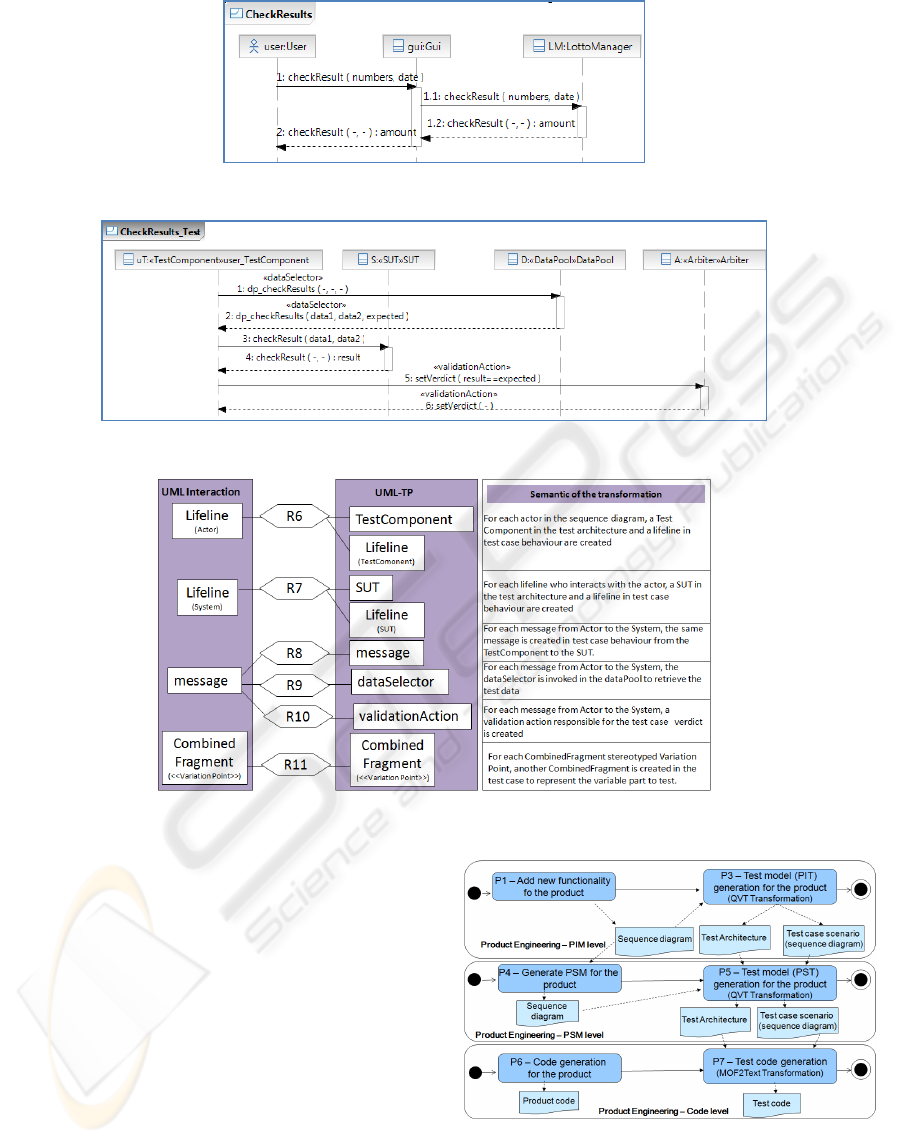
Figure 4: Check results functionality.
Figure 5: Test case for Check Results.
Figure 6: Semantic of QVT transformation for test case generation.
check the results for a bet in the Lotto game.
P3-Test Model Generation for the Product:
this activity consists of running the QVT scripts
which automatically generate the test models for
the product. The inputs for the transformation are
the sequence diagram generated in activity P1,
which were exported to the XMI format. The
outputs are the test architecture and the test case
scenario, both of which follow the UML-TP.
These models are imported to the modelling tool.
Using the UML-TP, actors are represented by
TestComponents, whilst the System is
represented by the SUT. In our proposal, each
message between the actor and the SUT must be
tested (functional testing). Figure shows the test
case generated for the Check Results
Figure 7: Framework activities in MDE development.
functionality in Figure . Figure summarizes the
semantics of the QVT transformation to generate
the test case scenario, in which the following
AN AUTOMATED MODEL-DRIVEN TESTING FRAMEWORK - For Model-Driven Development and Software
Product Lines
117
steps are necessary (more details can be found in
(Pérez Lamancha, Reales Mateo et al. 2009)):
Obtaining the Test Data: To execute the test
case, according to UML-TP, the test data are
needed and stored in the DataPool. The
TestComponent asks for the test data using the
DataSelector operation in the DataPool.
Figure
shows the dp_checkResult() stereotyped as
DataSelector which returns the values: data1,
data2 and expected. The first two are the values
to test the parameters in the operation and the
third is the expected result for the test case.
Executing the Test Case in the SUT: The
TestComponent simulates the actor and
stimulates the system under test (SUT). The
TestComponent calls the message to test in the
SUT. For the example in
Figure , the operation to
test is checkResult. It is tested with the data
returned by the DataPool. The operation is called
in the SUT and returns the result data.
Obtaining the Test Case Verdict: The
TestComponent is responsible for checking
whether the value returned for the SUT is
correct, and informs the Arbiter of the test result.
For the example in
Figure , the validation action
checks if the result (actual value) is equal to the
expected (expected value) to return a verdict for
the test case.
The activities at the PSM level are similar, but in
this case the models are refined with platform
specific aspects. The activities at code level are:
P6 – Code Generation for the Product: in this
activity the product code is generated following
specific MDE tools. Once the executable product
is obtained, it can be tested.
P3 – Test Code Generation for the Product:
this activity consists of running the MOF2Text
scripts which automatically generate the test
code from the PST model. The inputs for the
transformation are the sequence diagram that
represents the test cases generated in activities
P3 or P5. The output is the test case code
following the same development language used
at the PSM level. For example, if Java is used,
the test cases can be developed using JUnit.
5 TESTING FRAMEWORK FOR
SPL
This section describes the activities necessary to
implement the testing framework in SPL
development. The activities required for SPL are
added to those existing for MDE development.
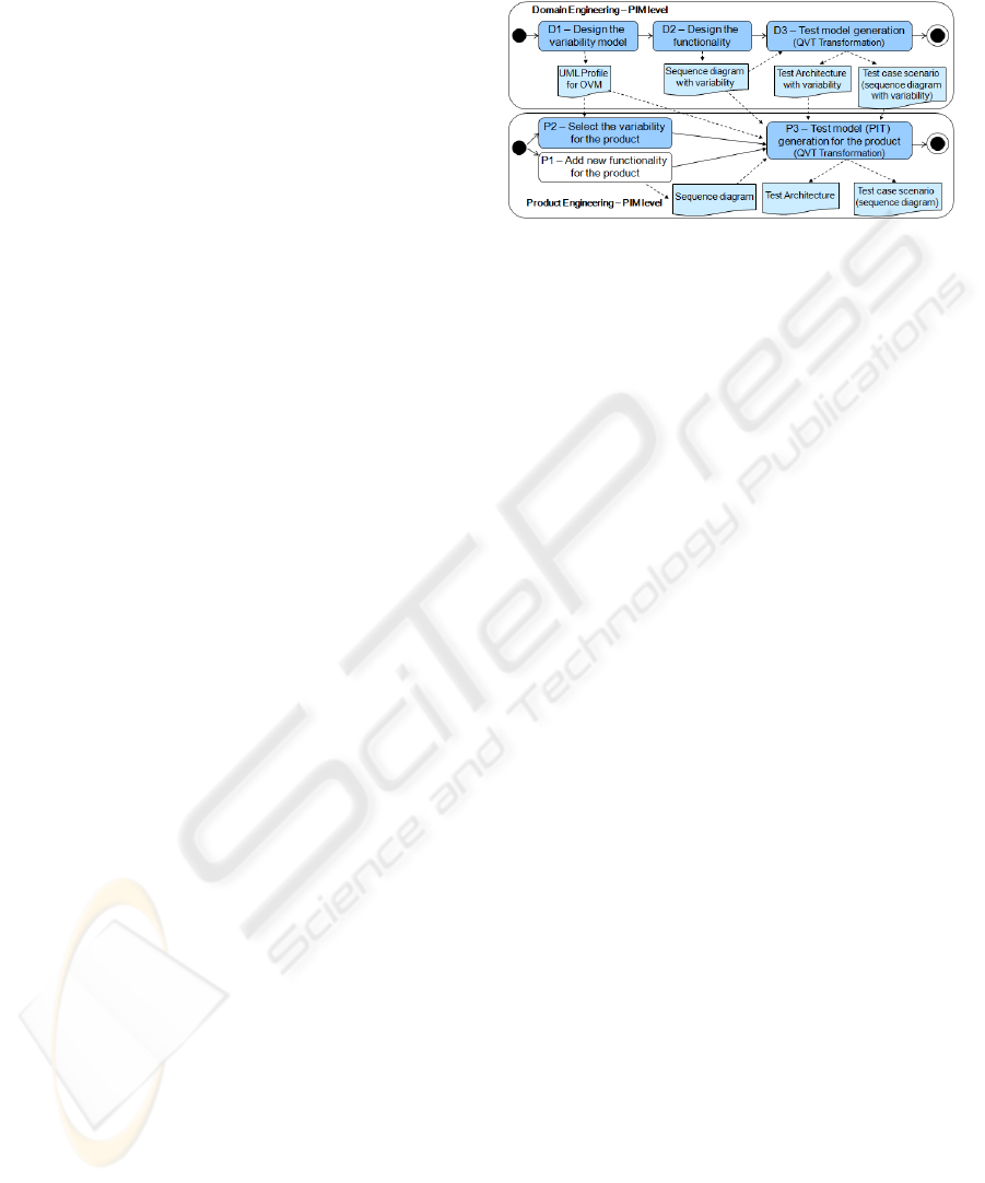
Figure shows the activities added to Figure .
Figure 8: Framework activities in SPL development.
For domain engineering, the activities added are:
D1 – Design the Variability Model: in this
activity, the OVM model for the SPL is
developed. This model follows the UML Profile
defined for OVM.
D2 – Design the Functionality: in this activity,
the common functionalities for the SPL are
described, including the variabilities. The results
are a sequence diagram with the extension
defined to deal with variability, where it
represents each variation point as a
CombinedFragment stereotyped with a Variation
Point. Each variant is an InteractionOperand in
the CombinedFragment. Figure 9 shows the Bet
Payment functionality for the Lottery SPL. In it,
the player calculates the amount of the bet and
then makes the payment. As can be seen in
Figure 1, the method of payment is a Variation
Point, and the Combined Fragment is thus
stereotyped as <<Variation Point>> in Figure 9.
In the Combined Fragment, the behaviour differs
if the payment is by credit card or with cash.
D3 – Test Model Generation: this activity
consists of running the QVT scripts which
automatically generate the test models for the
SPL. The inputs for the transformation are the
OVM model and the sequence diagram with
variability. The outputs are the test architecture
and the test case scenario, both of which follow
the UML Testing Profile and the extension
defined for variability. Figure 10 shows the test
case for Bet Payment, the same steps that the P3-
Test model generation for the product activity is
doing, but in this case, the CombinedFragment is
translated to the test case. More about test case
generation in the SPL context can be found in
(Pérez Lamancha, Polo Usaola et al. 2009).
In the product domain, the variability is resolved and
then the test model for each product is generated; the
activities added are:
ENASE 2010 - International Conference on Evaluation of Novel Approaches to Software Engineering
118
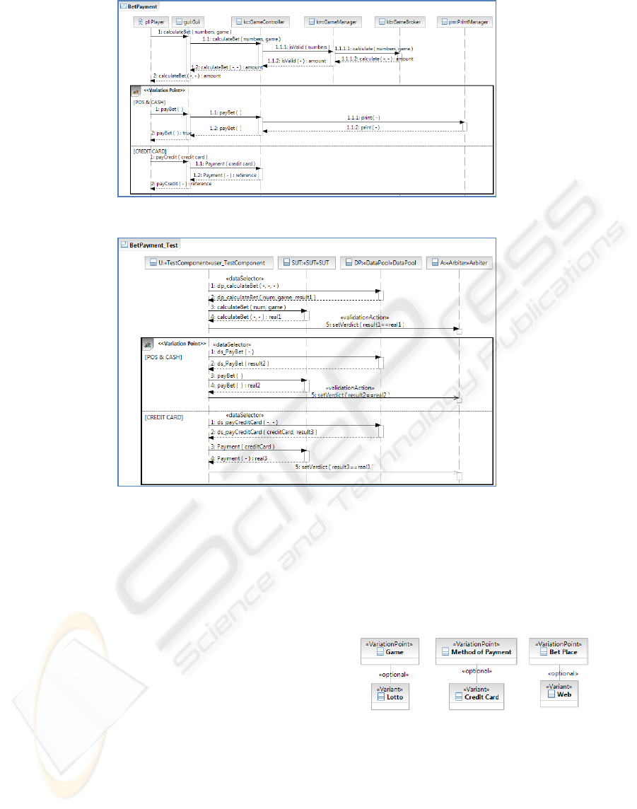
Figure 9: Bet Payment.
Figure 10: Test case for Bet Payment.
P1 – Add New Functionality for the Product:
in this activity, the functionality (which is
specific to the product) is described. The result is
a sequence diagram representing the
functionalities present only in this product. It is
the same activity as for MDE development.
P2 – Select the Variability for the Product: To
determine the test cases corresponding to each
product, it is necessary to know which variation
points and variants are included in each product.
In this activity, the valid variants for the product
are selected and this information is stored in the
Orthogonal Variability Model of each product
(OVMP). Figure 12 shows the variants selected
for the Lotto Web product.
P3 – Test Model Generation for the Product:
Taking the test case for Bet Payment (Figure 10)
as an example, to generate the test cases for the
product Lotto Web, the variability in the
CombinedFragment must be resolved. The inputs
are: (1) the variability model for the Lotto Web
(Figure 11), and (2) the Bet Payment_Test test
case (Figure 10). The output is the Bet
Payment_Test test case for the Lotto Web
product (Figure 12). The entire
CombinedFragment is deleted in the final test
case, i.e. the variability is resolved at the product
level.
Figure 11: Variability model for Lotto Web product.
The activities described in this section are added in
SPL development to what exists for MDE
development (see Figure 4). Furthermore, the
activities defined for the PSM and code level also
apply to SPL development.
AN AUTOMATED MODEL-DRIVEN TESTING FRAMEWORK - For Model-Driven Development and Software
Product Lines
119
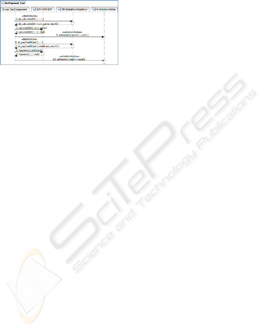
Figure 12: Bet Payment test case for Lotto Web Product.
6 RELATED WORKS
This section reviews the most significant works in
this field. Several proposals for test case generation
in SPL use UML artifacts as a basis. All of them
provide traceability between Domain and
Application Engineering in SPL. However, none of
them take into account the capabilities of standard
test models, such as UML-TP. Moreover, since
model-based approaches are quite suitable for SPL,
using a standard transformation language for
automating the model generation is quite
appropriate. A full description of existing works on
SPL can be found in a recently published systematic
review (Pérez Lamancha, Polo Usaola et al. 2009).
Nebut et al. (Nebut, Pickin et al. 2003) propose a
strategy in which test cases for each of the different
products of an SPL are generated from the same SPL
functional requirements. Test cases are obtained
from high level sequence diagrams. The test cases
for each product are derived from these sequence
diagrams. Bertolino et al. (Bertolino, Gnesi et al.
2004) propose an abstract methodology, PLUTO
(Product Line Use Case Test Optimization), for
planning and managing abstract descriptions of test
scenarios, which are described in PLUCs (Product
Line Use Cases). A PLUC is a traditional use case
where scenarios are described in natural language,
but also contain additional elements to describe
variability. Each PLUC includes a set of categories
(input parameters and environment description) and
test data. Then, and according to the variability
labels, categories are annotated with restrictions, to
finally obtain the test cases. Kang et al. (Kang, Lee
et al. 2007) use an extended sequence diagram
notation to represent use case scenarios and
variability. The sequence diagram is used as the
basis for the formal derivation of the test scenario
given a test architecture. Reuys et al. (Reuys,
Kamsties et al. 2005) present ScenTED (Scenario-
based Test case Derivation) where the test model is
represented as an activity diagram from which test
case scenarios are derived. Test case scenarios are
specified in sequence diagrams without providing
concrete test data. Test case scenarios can be
generated automatically, but test case specifications
are developed manually.
Olimpiew and Gomma (Olimpiew and Gomaa
2006) describe a parametric method, PLUS (Product
Line UML-based Software engineering). Here,
customizable test models are created during software
product line engineering in three phases: creation of
activity diagrams from the use cases, creation of
decision tables from the activity diagrams, and
creation of test templates from the decision tables.
Test data would then be generated to satisfy the
execution conditions of the test template.
Many proposals exist about model-based testing
but few of them focus on automated test model
generation using model transformation. Dai (Dai
2004) describes a series of ideas and concepts to
derive UML-TP models from UML models, which
are the basis for a future model-based testing
methodology. Test models can be transformed either
directly to test code or to a platform specific test
design model (PST). After each transformation step,
the test design model can be refined and enriched
with specific test properties. However, to the best of
our knowledge, this interesting proposal has no
practical implementation for any tool. These
transformations are carried out with Java algorithms,
which results in a mixed proposal between the two
approaches described in this paper.
Baker et al. (Baker, Dai et al. 2007) define test
models using UML-TP. Transformations are done
manually instead of with a transformation language.
Naslavsky et al. (Naslavsky, Ziv et al. 2007) use
model transformation traceability techniques to
create relationships among model-based testing
artifacts during the test generation process. They
adapt a model-based control flow model, which they
use to generate test cases from sequence diagrams.
They adapt a test hierarchy model and use it to
describe a hierarchy of test support creation and
persistence of relationships among these models.
Although they use a sequence diagram (as does this
proposal) to derive the test cases, they do not use it
to describe test case behaviour. They have plans to
use the traceability metamodel of ATL, but their
proposal has not been automated yet.
Javed et al. (Javed, Strooper et al. 2007) generate
unit test cases based on sequence diagrams. The
sequence diagram is automatically transformed into
a unit test case model, using a prototype tool based
ENASE 2010 - International Conference on Evaluation of Novel Approaches to Software Engineering
120

on the Tefkat transformation tool and MOFScript for
model transformation.
7 CONCLUSIONS
A framework for model-driven testing that can be
applied in MDE and SPL development was
presented. The proposal includes a methodological
approach to automate the generation of test models
from design models. In the case of SPL, a way to
handle the variability in test models is presented,
based on OVM. Currently, the proposal is
implemented for PIM models in domain and
application engineering. Future work includes
extending the proposal for PSM and code.
ACKNOWLEDGEMENTS
This research was financed by the projects: PRALIN
(PAC08-0121-1374) and MECCA (PII2I09-
00758394) from the “Consejería de Ciencia y
Tecnología, JCCM” and the project
PEGASO/MAGO (TIN2009-13718-C02-01) from
MICINN and FEDER. Beatriz Pérez has a grant
from JCCM Orden de 13-11-2008.
REFERENCES
Baker, P., Z. Dai, et al. (2007). Model-Driven Testing:
Using the UML Testing Profile, Springer.
Bertolino, A., S. Gnesi, et al. (2004). "PLUTO: A Test
Methodology for Product Families." PFE.
Clements, P. and L. Northrop (2001). Software Product
Lines - Practices and Patterns, Addison Wesley.
Czarnecki, K., M. Antkiewicz, et al. (2005). Model-driven
software product lines. OOPLSLA.
Dai, Z. (2004). Model-Driven Testing with UML 2.0.
EWMDA, Canterbury, England.
Dalai, S., A. Jain, et al. (1999). Model-based testing in
practice. ICSE.
Deelstra, S., M. Sinnema, et al. (2003). Model driven
architecture as approach to manage variability in
software product families. MDAFA.
Javed, A., P. Strooper, et al. (2007). Automated generation
of test cases using model-driven architecture. AST.
Kang, S., J. Lee, et al. (2007). "Towards a Formal
Framework for Product Line Test Development." CIT.
Mens, T. and P. Van Corp (2006). "A Taxonomy of Model
Transformation." Electronic Notes in Theoretical
Computer Sciences.
Miller, J. and J. Mukerji (2003). MDA Guide Version 1.0.
1. OMG.
Naslavsky, L., H. Ziv, et al. (2007). Towards traceability
of model-based testing artifacts. A-MOST.
Nebut, C., S. Pickin, et al. (2003). "Automated
requirements-based generation of test cases for
product families." ASE.
Olimpiew, E. and H. Gomaa (2006). "Customizable
Requirements-based Test Models for Software Product
Lines." SPLiT.
OMG (2002). Meta Object Facility Specification.
OMG (2003). MDA Guide version 1.0.1.
OMG (2005). UML testing profile Version 1.0.
OMG (2006). Object Constraint Language, Version 2.0.
OMG (2007). MOF Query/View/Transformation
Specification. v 1.0.
OMG (2007). Unified Modeling Language,
Superestructure specification.
OMG (2008). MOF Model to Text Transformation
Language, OMG.
Pérez Lamancha, B., M. Polo Usaola, et al. (2009). Model-
Driven Testing in Software Product Lines. ICSM.
Pérez Lamancha, B., M. Polo Usaola, et al. (2009).
Software Product Line Testing, A systematic review.
ICSOFT, Bulgaria.
Pérez Lamancha, B., M. Polo Usaola, et al. (2009).
Towards an Automated Testing Framework to Manage
Variability Using the UML Testing Profile. AST,
Canada.
Pérez Lamancha, B., P. Reales Mateo, et al. (2009).
Automated Model-based Testing using the UML
Testing Profile and QVT. MODEVVA, USA.
Pohl, K., G. Böckle, et al. (2005). Software Product Line
Engineering: Foundations, Principles, and Techniques,
Springer.
Reuys, A., E. Kamsties, et al. (2005). "Model-based
System Testing of Software Product Families."
CAiSE.
Trujillo, S., D. Batory, et al. (2007). Feature oriented
model driven development: A case study for portlets,
ICSE.
AN AUTOMATED MODEL-DRIVEN TESTING FRAMEWORK - For Model-Driven Development and Software
Product Lines
121
