
TRACE TRANSFORMATION REUSE TO GUIDE CO-EVOLUTION
OF MODELS
Bastien Amar, Herv
´
e Leblanc, Bernard Coulette
IRIT, Universit
´
e Paul Sabatier, 118 Route de Narbonne, F-31062 Toulouse Cedex 9, France
Philippe Dhaussy
ENSIETA - DTN, 2, rue F. Verny, 29806 Brest, France
Keywords:
Coevolution, Traceability, Model transformation.
Abstract:
With the advent of languages and tools dedicated to model-driven engineering (e.g., ATL, Kermeta, EMF),
as well as reference metamodels (MOF, Ecore), model-driven development processes can be used more eas-
ily. These processes are based on a large range of closely inter-related models and transformation covering
the whole software devolopment lifecycle. When a model is transformed, designers must re-implement the
transformation choices for all the related models, which raises some inconsistency problems. To prevent this,
we proposed trace transformation reuse to guide co-evolution of models. The contribution of this paper is a
conceptual framework where repercussion transformation can be easily deployed. The maturity of a software
engineering technology should be evaluated by the use of traceability practices.
1 INTRODUCTION
With the advent of languages and tools dedicated to
model-driven engineering (e.g., ATL (Jouault, 2006),
Kermeta (Drey et al., 2006), EMF (Budinsky et al.,
2003)), model-driven development processes can be
used more easily. Model Driven Engineering (MDE)
allows models to be considered as data and then used
as first class entities in dedicated transformations lan-
guages. As a result, recurring problems linked to soft-
ware production are emerging in this new develop-
ment context. Traceability practice is part of the mea-
sure of software process maturity. Thus MDE pro-
cesses should include traceability in their life cycle,
in particular since they are based on a large range of
models and transformations covering the whole soft-
ware development lifecycle, e.g. from requirements
and business models to platform and implementation
models, using weaving or refinement transformations.
The requirements management community is the
originator of the traceability concept. The IEEE Stan-
dard Glossary of Software Engineering Terminology
(IEEE, 1990) defines traceability as follows:
(1) The degree to which a relationship can be es-
tablished between two or more products of the de-
velopment process, especially products having a
predecessor-successor or master-subordinate rela-
tionship to one another; for example, the degree to
which the requirements and design of a given software
component match;
(2) The degree to which each element in a software
development product establishes its reason for exist-
ing; for example, the degree to which each element in
a bubble chart references the requirement that it sat-
isfies.
A definition of traceability links adapted to model
tracability is given in (Aizenbud-Reshef et al., 2006):
(1) Explicit links or mappings that are generated as a
result of transformations;
(2) Links that are computed based on existing infor-
mation;
(3) Links that are computed based on history provided
by change management systems on items that were
changed together as a result of one change request.
In relation to the first point of this definition, we
proposed an EMF plug-in which hunts any event to
infer traceability links during a Java/EMF transforma-
tion (Amar et al., 2008). . We used aspects-oriented
programming to catch transformation events in Java
programs and we stored trace links conformly to a
nested traces meta-model. We used this plug-in to an-
swer a co-evolution issue. When a model is trans-
73
Amar B., Leblanc H., Coulette B. and Dhaussy P. (2010).
TRACE TRANSFORMATION REUSE TO GUIDE CO-EVOLUTION OF MODELS.
In Proceedings of the 5th International Conference on Software and Data Technologies, pages 73-81
DOI: 10.5220/0003009200730081
Copyright
c
SciTePress

formed, designers must forward the transformation
choices to all related models, which raises some co-
herency problems. To prevent this, we proposed trace
transformation reuse to guide co-evolution of models.
The contribution of this paper is a tooled conceptual
framework dedicated to compose weaving and traces
models to keep inter-model coherency.
This paper is structured as follows. First, we
briefly present the main particularities of our ETrace-
Tool platform dedicated to trace imperative trans-
formations. Section 3 presents the issues encoun-
tered when ensuring inter-model consistency in co-
evolution case using a conceptual framework and a
model composition algorithm, which are presented
in Section 4. To illustrate our contribution, we de-
tailled in Section 5 one use of the presented frame-
work on a models refinement inspired by an indus-
trial case study. Section 6 shows how we can obtain
a requirement traceability scheme with an MDE ap-
proach. Section 7 concludes the paper.
2 TRACEABILITY OF MODEL
TRANSFORMATION
In MDE-oriented processes, different models are
made by the designer to represent the application.
These models are successively refined by programs
in order to generate (a part of) the final code. These
programs are called “models transformations”. This
section briefly describes our traceability platform,
ETraceTool, dedicated to trace imperative model
transformations. Further details can be found (Amar
et al., 2008).
Four main requirements have driven the design
and construction of ETraceTool:
• The trace generation code must not be intrusive in
the transformation code. This means that transfor-
mation code and code necessary to generate the
trace of the transformation should not be mixed,
as this would lead to too complex code for the
transformation.
• The trace generation must be explicitly activated
by the designer of the transformation. Tracing a
transformation can alter the efficiency of the trans-
formation and this is not necessary at each phases
of development of the transformation. Thus the
trace generation functionality should be easily en-
abled or disabled.
• The trace models are isolated from both the source
and target models involved in the transformation.
Another possible solution is that the trace en-
hances the source or the target model. However,
we believe that it would make the source or target
metamodels (which have to be enhanced with the
trace metamodel) too complex. Creating an inde-
pendant trace metamodel renders all the models
independent and easily readable. Merging trace-
ability links and models on demand is proposed
in (Kolovos et al., 2006).
• The generated trace models should be read using
different levels of granularity. Intuitively, the cre-
ation of an attribute can be considered as a sub-
level granularity link for the creation of a class
link.
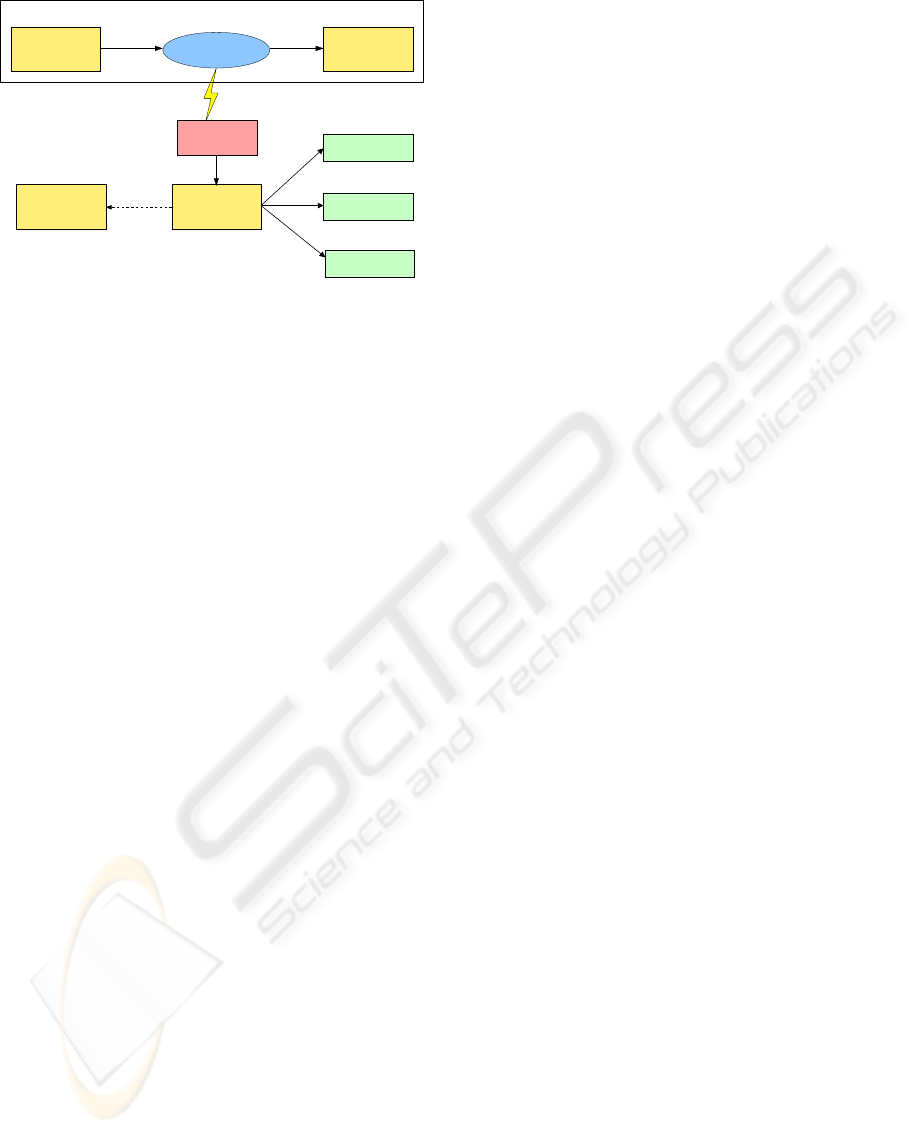
Figure 1 presents the overall architecture of
ETraceTool. The frame at the top represents the envi-
ronment, which is composed by a source model and
an imperative transformation, coded in Java with the
EMF API. The EMF project consists in a modeling
framework and code generation facility for building
tools and other applications based on structured data
models, which are conform to their metamodel. It in-
cludes a reference meta-meta-model (Ecore), and a
reflexive API used to manipulate models (Budinsky
et al., 2003). In the presented context, this API is
used to code model transformations.
During the execution of the transformation,
trasformation events are catched, using Aspect Ori-
ented Programming mechanisms (Kiczales et al.,
1997). We infer some categories of transformation
events and associate to each of them a pointcut. A
pointcut is an AOP concept used to defined location
in the application code. A piece of code is associ-
ated to each pointcut to make a trace. For example,
a method which uses one or more model elements as
parameters and returns a model element is referred to
as a transformation event: parameters are the source
elements and the returned element is the target. Those
events and their related code are defined in the aspect
Tracer.
Trace models are structured by a Nested Trace
Metamodel. It allows the user to generate multi-
scaled traces. The fact that an operation transforma-
tion can call another one (or that the rules can trigger
other rules) creates levels of nesting which it would
be useful to be able to represent.
At the end of the transformation execution, the
model can be serialised in the XMI format to save
it. To visualise and debug a model transformation,
the platform proposes a model-to-text transformation
which produces dot code. This code is used to
generate an annotated graph with the graphviz tool
(Gansner and North, 1999).
Using traces as input for transformations has been
proposed in (Vanhooff and Berbers, 2005) to facili-
tate the composition of complex transformations with
ICSOFT 2010 - 5th International Conference on Software and Data Technologies
74
Transformation
API EMF
Trace Model
XMI
Source Model Target Model
Conforms to
Trace Metamodel
Nested
Catching transformation events
Annotated Graph
Visualisation /
Debugging
Imperative Environment
Composition
of models
Inter−models coherency
Serialisation
Aspect Tracer
Figure 1: General ETraceTool architecture.
small transformation units. In (Aranega et al., 2009),
traces are used for model transformations testing and
errors localisation. In our case, traces allow us to
deal with inter-models consistency issues during a co-
evolution process, which is the main focus of this pa-
per.
3 CO-EVOLUTION AND
INTER-MODEL CONSISTENCY
Our work aims to guide the co-evolution process in
order to ensure an inter-model consistency. We have
adjusted the co-evolution of models (a term gener-
ally employed to ensure a conformity relationship be-
tween a model and a meta-model), and we defined the
inter-model consistency which was obtained.
Co-evolution of models generally deals with co-
evolution between metamodels and models (Cicchetti
et al., 2008; Hßler et al., 2005; Wachsmuth, 2007).
This issue is closely related to database schemas evo-
lution (Banerjee et al., 1987). The conformity re-
lation between schemas and data in object-oriented
databases is assumed by impacting schema changes
on existing instances. In the work of Cicchetti (Ci-
cchetti et al., 2008), a difference model was com-
puted from two versions of a metamodel. A co-
evolution transformation was generated from this dif-
ference model. For a set of standard metamodel refac-
torings, Heßler (Hßler et al., 2005) proposed a tech-
nique for a transition of the corresponding models to
new versions of the metamodel. A closely technique
is proposed by Wachsmuth in (Wachsmuth, 2007):
metamodel evolutions are done by small transforma-
tions, and each transformation implements a typical
adaptation step. We consider this type of co-evolution
as “vertical co-evolution”.
The co-evolution can also be considered as a
change propagation between models at the same
level of abstraction. We name this type of co-
evolution “horizontal co-evolution”. Change prop-
agating model transformations are those which can
make suitable updates to models after an initial trans-
formation. It is common to model systems using mul-
tiple interrelated models of different types. A typical
modeling paradigm provides a collection of domain
specific modeling languages, and/or multi-view lan-
guages such as UML (Salay et al., 2009). When one
of these models evolves, other related models have to
be correctly adjusted. The present work deals with
this type of co-evolution.
We have worked with UML and a domain specific
language, which are both different metamodels. In or-
der to clearly define the issues dealt with in this work,
some definitions must be set out.
Definition 1. A Master Model is the main model of a
system under development. It is generally represented
by several diagrams in UML or in a dedicated profile.
Definition 2. A Satellite model specifies properties
that cannot be expressed in UML. Generally, they are
described in textual languages (e.g. OCL, specific
logic language. . . ). These are not rules which would
lead to a well formed model, but they are used to ad-
dress elements of the master model.
Inter-model Consistency. In the modelling do-
main, one of the critical issues is to keep consistency
between models (Shinkawa, 2006). Models are said
to be consistent when they are coherent with one an-
other with reference to the requirement being mod-
elled (Sapna and Mohanty, 2007). To verify inter-
model (or models) consistency, OCL or logic rules
can be used (Sapna and Mohanty, 2007; Blanc et al.,
2009; Egyed, 2007). It is not the aim of the paper to
deal with consistency checks, but rather to help de-
signers to keep some kind of inter-model consistency.
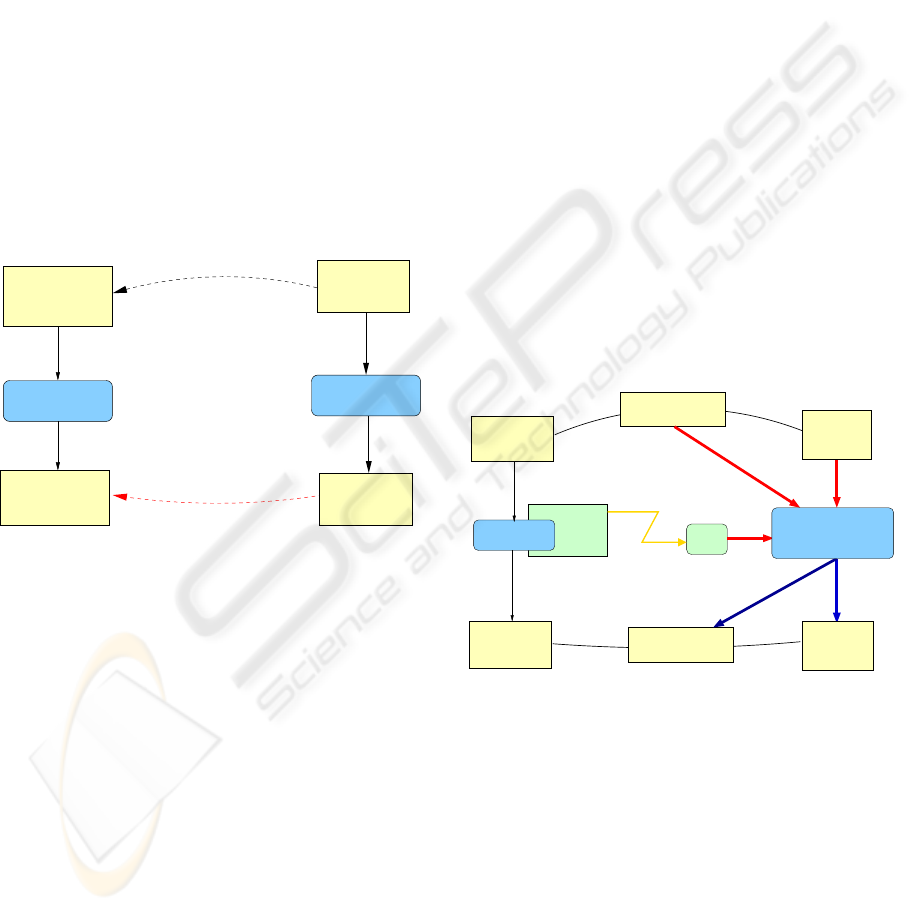
Figure 2 is a schematic representation of the con-
text of our work: a transformation of a source mas-
ter model (SMM) to a target master model (T MM),
and an inter-model consistency between the source
satellite model (SSM) and the source master model.
This inter-model consistency is the basis hypothesis
of valid co-evolution scenarii.
Hypothesis 1. Each referenced element in the source
satellite model is reached to a corresponding source
master model element.
If the satellite model represents a textual prop-
erty language, the consistency is checked by a simple
name equality. OCL can constrain the set of valid in-
stances of a meta-model, OCL can constrains UML
TRACE TRANSFORMATION REUSE TO GUIDE CO-EVOLUTION OF MODELS
75
models in the form of notes attached to model ele-
ments. Let a simple OCL rule be:
c o n t e x t A i r P l a n e
i nv : s e l f . n u m berOf S e at s >= 0
Hypothesis 1 is respected if a class AirPlane exists
and contains an attribute numberO f Seats.
Master models and Satellite models have to co-
evolve and the inter-model consistency between the
target satellite model and the master satellite model
must be maintained during this co-evolution. Sup-
pose we have a model-to-model transformation from
a class diagram to a syntax tree in Java. Suppose we
have a function that takes an OCL expression and re-
turns a Java assertion. The textual result on the simple
OCL rule can be:
a s s e r t t h i s . nu m b er O fS e a ts >= 0 :
t h i s . n u mb e r Of S ea t s ;
We can say that UML models and OCL expressions
co-evolve.
Transformation
Master
Inter−model consistency ?
Satellite
Transformation
Inter−model consistency
Model
Model
Master
Source
Master
Target
Source
Satellite
Model
Target
Satellite
Model
Figure 2: Context of our work.
Rule 1. Each referenced element in the target satel-
lite model is reached to a corresponding target master
model element.
In the example, we can reformulate in: each Java
assertion is reached to a corresponding Java class.
Rule 2. If a source master-model element is reached
by a satellite model element and this element is trans-
formed in one or many elements in the target master
model, then the reached element is transformed in the
same way.
In the example: if the attribute numberOfSeats
have been pulled up to a super-class, then the Java
assertion is reached now to the super-class. For rule
2, an intrinsic rule has to be respected: the transfor-
mation must preserve the non-transformed element in
the target model.
The solution proposed is to generate the satellite
model T (SMT ) from the both the satellite model S
(MMS) and the transformation execution, in order to
maintain the existing consistency between MMS and
SMS at the MMT and SMT level.
4 CONCEPTUAL FRAMEWORK
FOR REPERCUSSION
TRANSFORMATION
The present work deals with a conceptual framework
where a repercussion transformation takes place. The
general schema of our conceptual framework is pre-
sented in Figure 3. A source master model is trans-
formed into a target master model by a “Master trans-
formation”. The source master model has a satellite
model and the both are linked by an inter-consistency
relationship, expressed in a weaving model. The
ETraceTool is plugged onto the master transformation
and generates traces during the transformation execu-
tion. The traces, source satellite model and source
weaving model are inputs of a parametrised repercus-
sion transformation. This transformation produces a
target satellite model consistent with the target master
model. At the same time, a target weaving model is
generated.
Traces
ETraceTool
Transformation
Master
Source
Model
Master
Master
Model Model
Satellite
Model
Satellite
Target
Transformation
Repercussion
Weaving Model
Source
Target
Target
Source
Weaving Model
Figure 3: Conceptual framework for repercussion transfor-
mation.
Dealing with the inter-consistency relationship is
first presented, before describing the parametrised
repercussion transformation.
Creating a Weaving Model to Manage
Inter-model Consistency
According to the definition provided by Didonet Del
Fabro in (Didonet Del Fabro and Valduriez, 2009),
weaving models capture the relationships, or links be-
tween model elements. Weaving models enable the
ICSOFT 2010 - 5th International Conference on Software and Data Technologies
76

Algorithm 1: The repercussion transformation < makeElement(. . .) >.
Data: Source Satellite Model SSM;
Trace model T ;
SourceWeaving model SW M;
Target Master Model T MM
Output: Target Satellite Model T SM;
Target Weaving Model TW M
// initialization
T SM ← SSM;
TW M ← SWM;
foreach Pair (MasterModelElement mme; SatelliteModelElement sme) ∈ SW M do
{trace} traces ← searchTraces(T, mme);
if |traces| 6= 0 then
T SM ← T SM\{mme};
TW M ← TWM\(mme, sme) foreach t ∈ traces do
SatelliteModelElement newElement ← makeElement(t.target);
T SM ← T SM ∪ {newElement};
TW M ← TW M ∪ {(t.target;newElement)};
end
end
end
{trace} Function searchTraces(TraceModel T, MasterModelElement mme) is
{trace} traces;
foreach trace t ∈ T do
if mme source of t then
traces ← traces ∪ {t};
end
end
return traces;
end
weaving models capture the relationships, or links be-
tween model elements. Weaving models enable the
creation of abstract links between elements from dif-
ferent models, although they are not executable. A
complete metamodel was proposed by Didonet Del
Fabro in (Didonet Del Fabro and Valduriez, 2009), the
key idea being the reification of links between models
by the WLink class. We have named this class “Pair”,
and used a simpler metamodel consisting in a list of
pairs. Each pair references one element of the mas-
ter model and on element of the satellite model. The
source weaving metamodel allows the user to express
hypothesis 1.
The Repercussion Transformation
The main principle of a repercussion transformation
is to use transformation traces to re-execute the mas-
ter transformation on satellite models. It takes three
inputs:
• the traces model;
• the source satellite model, which represents the
set of properties to adjust;
• and the source weaving model, which ensures, via
the trace models, that the source satellite model
elements are transformed.
Two outputs are generated:
• the target satellite model, which represents the ad-
justed properties;
• the target weaving model, which allows to con-
tinue the MDE process and chain transformations.
At the next transformation, this will be the source
weaving model.
Our generic repercussion algorithm is given re-
specting the set theory.
The algorithm implements a model composition.
The source weaving model and the searchTraces op-
eration allow to retrieve all the generated elements
in the target master model. The substitution and the
generation of the target weaving model is executed
for each traces returned by the searchTrace function.
Each retrieved element serve as input to the makeEle-
ment fonction and the satellite element is assigned.
The target weaving model was generated simultane-
ously . makeElement creates a new satellite model
element from a master model element. As a result, it
is strongly coupled to the master and satellite meta-
models. This part of the algorithm is implemented by
the user. This method is a parameter of our algorithm.
TRACE TRANSFORMATION REUSE TO GUIDE CO-EVOLUTION OF MODELS
77
5 APPLICATION TO A
REFINEMENT
TRANSFORMATION
This section describes an application of the repercus-
sion framework on a refinement transformation based
on a simplified case study in the field of avionics com-
munication protocols. This case study was conducted
as a part of DOMINO (DOMINO, 2009), a Research
National Agency (ANR) project.
The original case study is supported in CDL
(Dhaussy et al., 2009). , a domain specific language
developed for embedded systems. CDL aims to pre-
cisely specify/restrict the behaviour of a system en-
vironment by modelling the interaction between the
system and its environment. After an MDE process,
model checking technique is used to prove the system
is working properly.
CDL includes on the one hand a part of UML and
on the other hand temporal properties. To simplify
the presentation of the different models involved, only
UML2.0 sequence diagrams are presented and the
properties are expressed in a simple and intuitive do-
main specific language.
5.1 Description of the Source Models
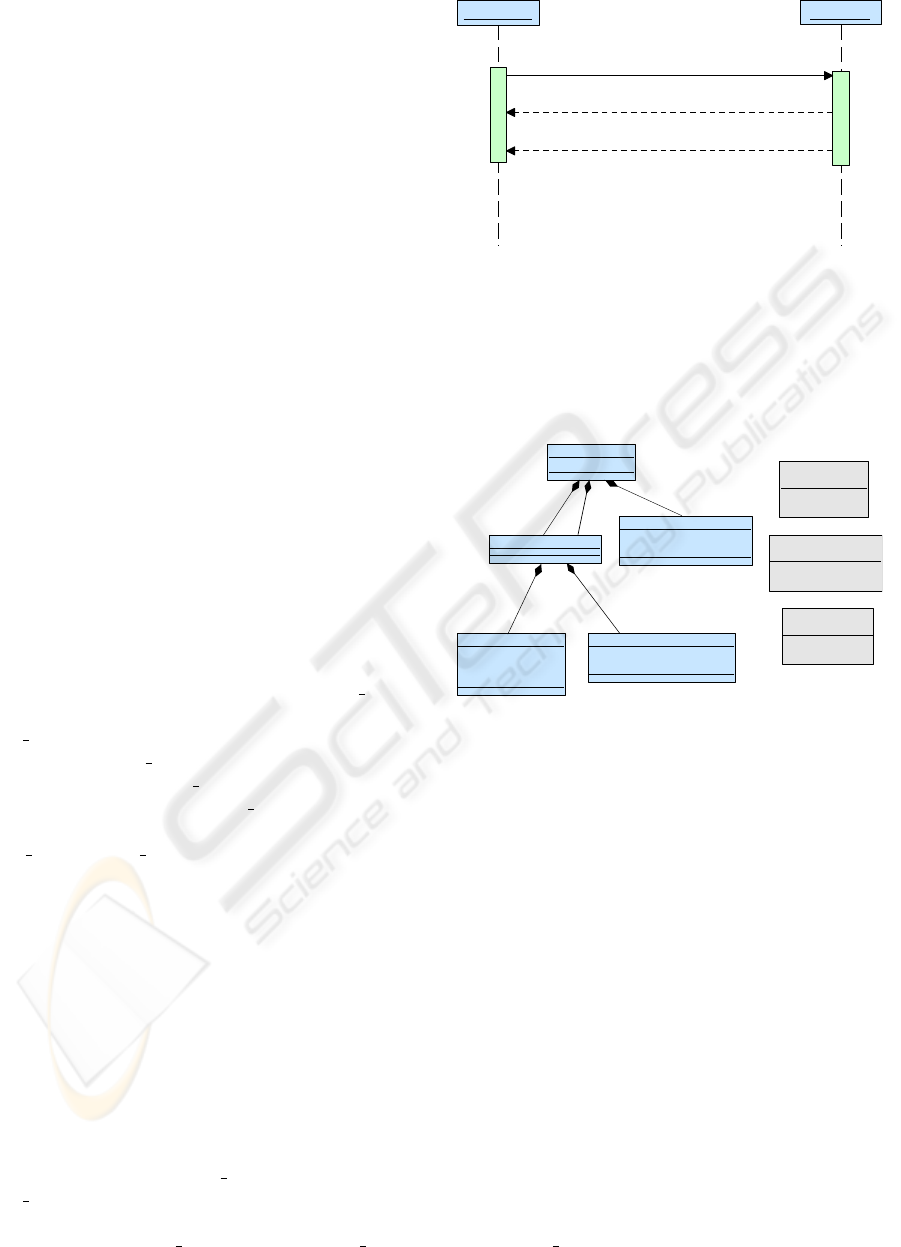
Figure 4 illustrates an abstract protocol between ab-
stract machines. It represents an exchange of informa-
tion between the plane (represented by the ATC board
component) and a ground station (represented by
ATC ground component). The execution scenario
is as follows: ATC board component initialises the
communication by the FN CON message which spec-
ifies a login demand to the ATC ground component.
It then waits for two acknowledgments of receipt
ACK NSP and FN ACK corresponding respectively
to a network acknowledgment and a connection de-
mand acknowledgment. This interaction is described
by a sequence diagram.
Associated to the interaction model, temporal
properties P1 and P2 are expressed according to:
<ATC_board>FN_CON!
leads-to<tnsp
<ATC_board>ACK_NSP? (P1)
<ATC_board>FN_CON!
leads-to<tfn
<ATC_board>FN_ACK? (P2)
P1 (respectively P2) expresses that the emis-
sion (noted “!”) of the FN CON message by the
ATC board component must be followed by the re-
ception, by this same component, of the acknowl-
edgment message ACK NSP (respectively FN ACK)
b :
s
:
FN_CON
ACK_NSP
AFN_ACK
ATC_Board
ATC_Ground
Figure 4: The interaction between two abstract components.
within tnsp (respectively t f n) time units. The meta-
model of this language is presented in Figure 5. Two
ListEvent form a property (the right part and the left
part). A ListEvent has a Scope constituted by two at-
tributes: a Multiplicity and an Order.
Propert y
+ name : EString
List Event
<<enumeration>>
MultiplicityName
an
all
<<enumeration>>
OrderName
Order
Combined
LeadsTo
+ immediacy : EBoolean
+ time : EInt
Event
+ name : EString
+ machine : EString
+ nature : Nature
Scope
+
multiplicity
: MultiplicityName
+ order : OrderName
<<enumeration>>
Nat ure
Sending
Receipt
+left
1
+right
1
+leadsTo
1
+OccurenceEventList
1..*
+scope
1
Figure 5: Part of the metamodel of the domain specific lan-
guage used to express temporal properties.
As explained in section 3, there is a inter-
consistency relationship between temporal properties
and the associated UML model. This weaving model
(i.e. a list of pair) is presented in table 1. One property
event is associated with an UML MessageOccurence-
Specification: in the UML metamodel, a message is
subdivided in two parts, the sending and the receipt.
The type of these parts is MessageOccurenceSpecifi-
cation and it includes references to both machine and
message. Multiplicity is used if the ListEvent contains
several Events and indicates if one or several Event is
expected. Order specifies if the ListEvent is ordered.
5.2 Transformation and Results
During the architecture refinement process, the de-
signer makes choices to concretely implement the ab-
stract protocol. We assume the following implemen-
tation choices:
• the ATC board component is refined in three con-
ICSOFT 2010 - 5th International Conference on Software and Data Technologies
78
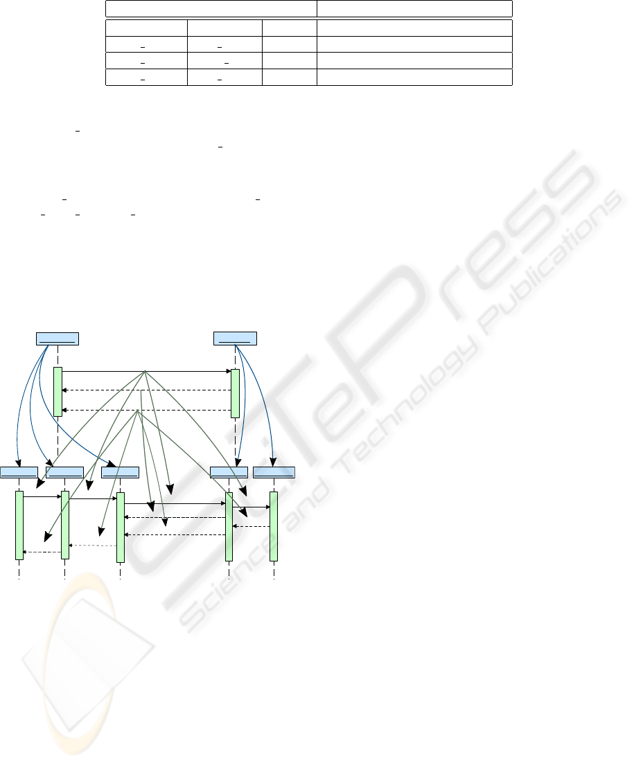
Table 1: Representation of the source weaving model.
Property events MessageOccurenceSpecification
Machine Name Nature XMI reference
ATC Board FN CON ! SendFnCon
ATC Board ACK NSP ? ReceiveAckNsp
ATC Board FN ACK ? ReceiveFnAck
crete components : ATCHMIM, AFN and AGCM.
• The ATC ground component is refined in two
concrete components NSP and ATC Center.
• Each message of the abstract model is refined by
an ordered sequence of messages. For instance,
the FN CON message is refined in: Afn logon,
Afn agcm rq, Agcm rq.
The result of the transformation is presented in
Figure 6 as a trace oriented schema. The most inter-
esting parts of the obtained traces are represented by
the arrows. However, this results in a finer granular-
ity of the trace model because of the UML metamodel
complexity.
b :
s
:
FN_CON
ACK_NSP
AFN_ACK
ATC_Board
ATC_Ground
at
:
ATCHMIM
afn
:
AFN
a
:
AGCM
nsp
:
NSP
c
:
ATC_Center
afn_logon
afn_ack
afn_agcm_rq
afn_agcm_id
agcm_rq
ack_nsp
agcm_id
atc_rq
atc_id
Figure 6: Part of the traces between source and target master
model.
Traces are used as inputs of our repercussion al-
gorithm. The makeElement operation is strongly cou-
pled to the different metamodels used by the trans-
formation: in this case, an Event is computed from
an UML MessageOccurenceSpecification. This op-
eration creates a new Event, and fills its attributes
from MessageOccurenceSpecification recovered in-
formation. For example, getting the machine name
(represented by an UML class name) from a Mes-
sageOccurenceSpecification implies the execution of
a request which navigates into the UML metamodel.
Once the repercussion algorithm is executed, we
obtain two outputs: the adapted property coherent
with the target master model. These two properties
are represented as models, and a model-to-text trans-
formation produces the textual properties, P’1 and
P’2. The All ORDER (x ; y) statement indicates an
ordered sequence of the events x and y, and it is added
by the model-to-text transformation.
All ORDER(<ATCHMIM>Afn_logon!;
<AFN> Afn_agcm_rq!;
<AGCM>Agcm_rq!)
leads-to<tnsp
<AGCM>Ack_nsp?
(P’1)
All ORDER(<ATCHMIM>Afn_logon!;
<AFN>Afn_agcm_rq!;
<AGCM>Agcm_rq!)
leads-to<tfn
All ORDER(<AGCM>Agcm_id?;
<AFN> Afn_agcm_id?;
<ATCHMIM>Afn_ack?)
(P’2)
To ensure the inter-consistency relationship of the
generated models, and to allow the user to verify
and validate the obtained satellite model, the target
weaving model is generated, linking both the mas-
ter model elements (MessageOccurenceSpecification)
and the satellite model elements (Event). This model
is represented in table 2
To summarise, the extension of the framework
for our case study consists in programming the
makeElement operation, which computes an Event
from an UML MessageOccurenceSpecification, and
in programming a simple model-to-text transforma-
tion from a CDL model to its textual representation.
6 TRACEABILITY OF
REQUIREMENTS
In complex system development, an important part of
the activities are the identification and specification of
requirements. In an MDE approach, requirements are
models. These models must be verified on the system
models at a given level of abstraction. When a model
described at an abstract level n is refined to a concrete
level n + 1, the requirements expressed at the level
TRACE TRANSFORMATION REUSE TO GUIDE CO-EVOLUTION OF MODELS
79
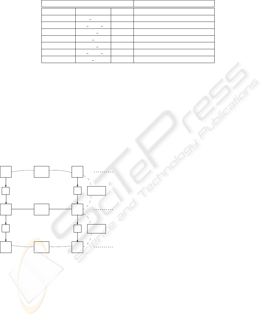
Table 2: Representation of the target weaving model.
Property events MessageOccurenceSpecification
Machine Name Nature XMI reference
ATCHMIM afn logon ! SendAfnLogon
AFN afn agcm rq ! SendAfnAgcmRq
AGCM agcm rq ! SendAgcmRq
AGCM ack nsp ? ReceiveAckNsp
AGCM agcm id ? ReceiveAgcmId
AFN afn agcm id ? ReceiveAfnAgcmIs
ATCHMIM afn ack ? ReceiveAfnAck
n have to be refined. When this refinement is done,
the level n + 1 requirements reference the system ele-
ments at level n + 1.
In this paper, we have shown how properties can
be refined in the same way than system elements. At
each level of modeling, properties must be correctly
adjusted. However, we lack a trace level to ensure re-
quirement traceability from our point of view: traces
between refined requirements.
Let consider the two following hypotheses :
• Models are used to encode requirements (Ramesh
and Jarke, 2001);
• Properties address system elements.
MM
MM
MM
T
T
level n
level n+1
level n+2
WM
WM
WM
SM
SM
SM
R
R
Traces
Traces
Figure 7: Traceability of requirements.
The left part of Figure 7 represents the system
models refinement, modeled by master models (de-
noted MM). The right part represents requirements
refinements. The traces between requirement ele-
ments (defined in satellite model SM) allow the user
to know how a requirement was refined, and what
elements of the system it supports. We have a tool
to recover the traces of any transformations written
in Java/EMF that we apply to our own repercussion
transformation. Following the approach of MDE,
we operate along the refinement chain (as described
by Vanhooff in (Vanhooff and Berbers, 2005)) with
our traceability tools and repercussion transforma-
tion, therefore contributing to the traceability of re-
quirements.
7 CONCLUSIONS
This paper has presented tooled conceptual frame-
work dedicated to compose weaving and traces mod-
els to keep inter-model consistency in co-evolution
cases. A prototype has been developed and tested on
an industrial case study in the field of avionic commu-
nication protocol, as a part of the DOMINO project.
We obtained pertinent traces and the specific exten-
sion of the framework correctly adjusts the proper-
ties. A right target weaving model is generated. This
MDE process is tested on the TOPCASED environ-
ment, dedicated to the realisation of critical embed-
ded systems (Vernadat et al., 2006). The following
research fields will be the next focus of our work.
First, we aim to adapt the repercussion frame-
work and ETraceTool to transformation of multiple
models. Most of the transformation developed in
industrial cases takes several models as inputs, and
produces several models. We successfully applied
our platform on a bigger transformation taken from
the aerospace field, provided by the CNES (National
Center of Space Studies). As input of this transfor-
mation there are two main master models: an activity
diagram which represents a procedure to apply to per-
form a specific task, and various technical statements
used to express all the possible low-level satellite ma-
nipulation commands. The target model is a gram-
marware model of a procedural language for satellite
manipulation. We obtained traces from this transfor-
mation. Properties are expressed on interaction dia-
gram elements and we aim to code them in the target
language.
Then, we will test our platform on chained trans-
formations and validate our framework on a large-
scale environment. The ideal case is an abstract model
coupled with requirements (expressed in a satellite
ICSOFT 2010 - 5th International Conference on Software and Data Technologies
80

model) refined step by step, in order to produce code.
Following the approach of MDE, if we tool all along
a refinement chain with our traceability tools we to
obtain requirements traceability.
REFERENCES
Aizenbud-Reshef, N., Nolan, B. T., Rubin, J., and Shaham-
Gafni, Y. (2006). Model traceability. IBM System
Journal, 45(3):515–526.
Amar, B., Leblanc, H., and Coulette, B. (2008). A Trace-
ability Engine Dedicated to Model Transformation for
Software Engineering. In ECMDA Traceability Work-
shop 2008, Berlin, pages 7–16.
Aranega, V., Mottu, J.-M., Etien, A., and Dekeyser, J.-L.
(2009). Traceability mechanism for error localization
in model transformation. In 4th International Confer-
ence on Software and Data Technologies (ICSOFT),
Sofia, Bulgaria.
Banerjee, J., Kim, W., Kim, H.-J., and Korth, H. F.
(1987). Semantics and implementation of schema
evolution in object-oriented databases. SIGMOD
Record, 16(3):311–322.
Blanc, X., Mougenot, A., Mounier, I., and Mens, T. (2009).
Incremental detection of model inconsistencies based
on model operations. In CAiSE ’09: Proceedings of
the 21st International Conference on Advanced In-
formation Systems Engineering, pages 32–46, Berlin,
Heidelberg. Springer-Verlag.
Budinsky, F., Grose, J. T., Steinberg, D., Ellersick, R., and
Merks, E. (2003). Eclipse Modeling Framework: a
developer’s guide. Addison-Wesley Professional.
Cicchetti, A., Ruscio, D. D., Eramo, R., and Pieranto-
nio, A. (2008). Automating co-evolution in model-
driven engineering. In EDOC ’08: Proceedings of the
2008 12th International IEEE Enterprise Distributed
Object Computing Conference, pages 222–231. IEEE
Computer Society.
Dhaussy, P., Pillain, P.-Y., Creff, S., Raji, A., Le Traon,
Y., and Baudry, B. (2009). Evaluating context de-
scriptions and property definition patterns for software
formal validation. In Springer-Verlag, editor, Model
Driven Engineering Languages and Systems, volume
5795, pages 438–452.
Didonet Del Fabro, M. and Valduriez, P. (2009). Towards
the efficient development of model transformations
using model weaving and matching transformations.
Software and Systems Modeling, 8(3):305–324.
DOMINO (2009). DOMaINes et prOcessus
mthodologique.
http://www.domino-rntl.org/.
Drey, Z., Faucher, C., Fleurey, F., and Vojtisek, D. (2006).
Kermeta language reference manual.
Egyed, A. (2007). Fixing inconsistencies in UML design
models. In Proceedings of the 29th International
Conference on Software Engineering, pages 292–301.
IEEE Computer Society.
Gansner, E. R. and North, S. C. (1999). An open graph
visualization system and its applications. Software -
Practice and Experience, 30:1203–1233.
Hßler, J., Soden, M., and Eichler, H. (2005). Coevolution of
models, metamodels and transformations. Models and
Human Reasoning. Wissenschaft und Technik Verlag,
Berlin, pages 129–154.
IEEE (1990). Standard Glossary of Software Engineering
Terminology: IEEE Std 610.12-1990. Technical re-
port, IEEE.
Jouault, F. (2006). Contribution to the study of model trans-
formation languages. PhD thesis, Universit de Nantes.
Kiczales, G., Lamping, J., Menhdhekar, A., Maeda, C.,
Lopes, C., Loingtier, J.-M., and Irwin, J. (1997).
Aspect-oriented programming. In Proceedings Eu-
ropean Conference on Object-Oriented Programming,
volume 1241, pages 220–242. Springer-Verlag.
Kolovos, D. S., Paige, R. F., and Polack, F. A. (2006).
On-demand merging of traceability links with mod-
els. In ECMDA-TW 2006 Proceedings, Bilbao, July
11th 2006, pages 7 – 15.
Ramesh, B. and Jarke, M. (2001). Toward reference models
for requirements traceability. IEEE Transactions on
Software Engineering, 27(1):58–93.
Salay, R., Mylopoulos, J., and Easterbrook, S. (2009). Us-
ing Macromodels to Manage Collections of Related
Models. In Proceedings of the 21st International Con-
ference on Advanced Information Systems Engineer-
ing, pages 141–155. Springer-Verlag.
Sapna, P. and Mohanty, H. (2007). Ensuring consistency in
relational repository of UML models. In 10th Inter-
national Conference on Information Technology (ICIT
2007), pages 217–222.
Shinkawa, Y. (2006). Inter-model consistency in uml based
on cpn formalism. Asia-Pacific Software Engineering
Conference, pages 411–418.
Vanhooff, B. and Berbers, Y. (2005). Supporting modu-
lar transformation units with precise transformation
traceability metadata. In ECMDA-Traceability Work-
shop, Nuremberg, pages 16 – 27.
Vernadat, F., Percebois, C., Farail, P., Vingerhoeds, R.,
Rossignol, A., Talpin, J.-P., and Chemouil, D. (2006).
The TOPCASED Project - A Toolkit in OPen-source
for Critical Applications and SystEm Development.
In Data Systems In Aerospace (DASIA), Berlin, Ger-
many.
Wachsmuth, G. (2007). Metamodel adaptation and model
co-adaptation. In Ernst, E., editor, Proceedings of
the 21st European Conference on Object-Oriented
Programming (ECOOP’07), volume 4609 of Lecture
Notes in Computer Science, pages 600–624. Springer-
Verlag.
TRACE TRANSFORMATION REUSE TO GUIDE CO-EVOLUTION OF MODELS
81
