
EXTENDING UML TO REPRESENT INTERACTION ROLES
AND VARIANTS OF DESIGN PATTERN
Keen Ngee Loo and Sai Peck Lee
Department of Software Engineering, Faculty of Computer Science and Information Technology
University of Malaya, 50603 Kuala Lumpur, Malaysia
Keywords: Design pattern, Interaction role, Interaction variant, UML profile.
Abstract: There are various descriptions, structures and behavior on the solution for a design problem in a design
pattern. However, there is not much visual aid on the internal workings of a design pattern in a visual design
modeling tool. Currently, it is difficult to determine the pattern roles and variants of interaction groups of a
design pattern as these information is not represented in the UML interaction diagram. There is a need to
have a consistent way to define the pattern roles participating in a design pattern interaction and whether
there is a variant in each interaction group. This paper proposes to extend the UML sequence diagram via
UML profile to allow designers to define and visualise the pattern roles and the different types of interaction
groups for a design pattern. The proposed extensions are able to capture the two ways of design pattern
interaction variants in sequence diagram. An example of the approach is then applied to the observer design
pattern. The benefit of the extension enables tool support on cataloguing and retrieval of design patterns’
structural and behavioural information as well as variant in a visual design modeling tool.
1 INTRODUCTION
According to (Budgen 2003), software design is a
type of problem solving or decision. Design is a
mean to produce a solution to a problem. Designers
sometimes use multiple approaches to a design
problem and may not follow a single method
(Budgen 2003). Empirical studies available on actual
design activities have observed only a little use of
method practices and the procedural method based
design may be modified significantly during use and
(Budgen 1999). Hence, another means of
transferring design knowledge and experience can
be achieved through design patterns, design
architecture and tools in addition to procedural
design method (Budgen 1999).
Design patterns encapsulate the experience,
provide a common vocabulary for computer
scientists across the domain barrier and enhance the
documentation of software (Agerbo & Cornils
1998). Software design pattern is also seen as one of
the knowledge important to software professional in
a survey done by (Lethbridge 2000). The most well
known catalogue of design patterns in software is
presented in (Gamma et al. 1995).
During designing, designers may want to apply a
certain design pattern to their design. The lack of
visual aid on how it interacts can be difficult
especially for novice designers when looking only at
the structure alone. By looking at the structure of a
design pattern, e.g. Figure 1, it can be hard to
identify what interactions occur among the pattern
roles and what pattern roles the elements in the
interaction participate in. There is a lack of a
consistent way to define how groups of interactions
occur among the classes in the design pattern and
whether there is a variant in each interaction group.
In addition, some definition of the behavioural
information is defined in a mixture of specific
programming language and UML class elements on
how the pattern works. As shown in Figure 1, C++
programming language is used to describe the
behaviour using the UML note element.
Programming language code can be useful at the
programming level to execute how the design
pattern works. However, we would like to think
about the design pattern as a higher abstraction level
design than the code level that can be implemented
in different programming languages and about the
variant of design ideas. Capturing the behavioural
information of design patterns a t the UML model
level has its advantages, as the patterns can be less
201
Ngee Loo K. and Peck Lee S. (2010).
EXTENDING UML TO REPRESENT INTERACTION ROLES AND VARIANTS OF DESIGN PATTERN.
In Proceedings of the 5th International Conference on Software and Data Technologies, pages 201-207
DOI: 10.5220/0003009602010207
Copyright
c
SciTePress
Subject
+attach(o:Observer)
+detach(o:Observer)
+notify()
Observer
+update()
ConcreteSubject
-subjectState
+getState()
+setState()
ConcreteObserver
-observerState
+update()
objectState=subject->getState()return subjectState
notifies
observes
for all o in observers
{
o->update();
}
*
Figure 1: Observer Design Pattern defined in UML Class
Diagram.
dependent on programming languages. In the area of
model driven architecture (MDA) (OMG), some
works in the area employ model transformation to
convert the model to specific programming
language.
Visualising the interaction and its variants can
aid adaptation of the appropriate design pattern.
Design patterns that are closely related can be
differentiated from one another and can be further
specialised. This paper proposes to identify the
pattern roles, interaction groups and its variants in
design patterns via profile based extension to UML
sequence diagram.
The remainder of this paper is organised as
follows. The next section presents the proposed
approach. Section III shows an example of the
approach on observer design pattern. Section IV
presents the discussion, and finally, Section V
provides a conclusion.
2 PROPOSED APPROACH
UML has two ways of extending its language, one is
through extending the metamodel directly and
another is through its extension mechanism called
UML profile. UML profile is used for adapting the
UML model for specialised domain (OMG 2007).
UML profile is chosen as the extension method as it
is generally supported in standard UML tools
compared to extending the metamodel directly.
Sequence diagram is chosen to show the pattern
interaction as it has the properties that help to
decompose large interactions into smaller
interactions via InteractionUse. InteractionUse can
also be used to describe parts of the interaction in
another sequence diagram. The decomposition of the
sequence diagram helps organise the different
operations instead of having a large set of
Figure 2: Design Pattern Interaction Profile.
interactions in a single diagram which can be
difficult to manage. It is easier to see interaction
groupings in the sequence diagram in comparison to
communication diagram as in the communication
diagram the groupings are by the numbering
notation.
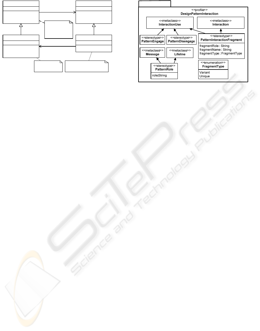
In Figure 2, the proposed UML profile named
DesignPatternInteraction is shown. In the profile,
stereotype PatternRole extends Message and Lifeline
metaclass. It is used to define the pattern role of a
Message and Lifeline via the tag definition role. It
has the syntax of patternRole@DesignPattern. The
patternRole here refers to the participant type in the
DesignPattern. For example, if we have pattern role
X in design pattern Y, we then denote the tagged
value for role as X@Y. It is then read as “pattern role
X at design pattern Y”.
Three extensions are made to the InteractionUse
and each has different purposes:
• PatternEngage is a fragment that contains the
interactions that occur when a new pattern role is
added to a particular design pattern.
• PatternDisengage is a fragment that contains the
interactions that occur when a pattern role is
removed from a particular design pattern.
• PatternInteractionFragment is a general fragment
that contains the interactions that exist in a
particular design pattern.
PatternInteractionFragment stereotype contains
three tagged definitions i.e. fragmentRole,
fragmentName and fragmentType. The
fragmentRole is used to define the role of the
particular fragment with a syntax of
fragmentRole@DesignPattern. The fragmentRole
here refers to the fragment role in the
DesignPattern. For example, if we have fragment
role W in design pattern Z, we then denote the
value for tagged definition fragmentRole as W@Z.
It is then read as “fragment role W at design
ICSOFT 2010 - 5th International Conference on Software and Data Technologies
202
pattern Z”. The fragmentRole is also used to
determine whether there are more than one variant
for a particular fragment. For example, if there
exist two fragments with the same fragmentRole
value and the corresponding fragmentType value
is Variant, it means that the fragment has two
variants. The fragmentName could then be used to
differentiate the fragments using a distinctive
name. FragmentType can have value of either
Variant or Unique. If a fragmentType value of a
fragment is Unique, it means that the fragment
currently has no variant. However, the
FragmentType for a fragment can be changed
from Unique to Variant when new additional
variants are found and needs to be defined. This is
done by adding a new corresponding
PatternInteractionFragment with fragmentType
value of Variant. The various fragments that exist
can be useful not only to see the base design
pattern but also to differentiate the variant of
interactions that may occur when finding a
suitable pattern for a specific problem that the
designer is trying to solve.
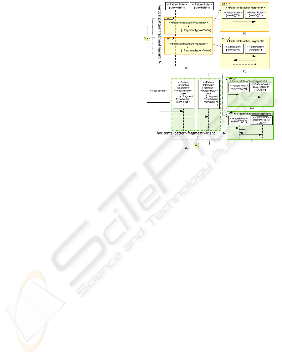
In defining the variant for a design pattern
interaction using PatternInteractionFragment, two
ways of variant called the vertical pattern fragment
variant (VPFV) and horizonzal pattern fragment
variant (HPFV) have been identified. It indicates the
direction of fragment variant growth in a sequence
diagram. As PatternInteractionFragment extends
InteractionUse metaclass, the extension is applicable
for both PartDecomposition and InteractionUse
metaclasses as PartDecomposition is a specialization
of InteractionUse. VPFV exists when there is a
variant of interaction among the same pattern
fragment role as shown in Figure 3 (a) (c) (d). Due
to space constraint, some of the extended tagged
definitions are not shown in the diagram.
Conversely, HPFV exist when there is a variant on
the pattern’s lifeline as shown in Figure 3 (b) (e) (f).
HPFV is used when there are possibilities that a
message sent from a sender is received via another
patternRole. For example, a pattern role
ConcreteSubject in an observer design pattern may
not interact with pattern role ConcreteObserver
directly but via a proxy design pattern as will be
discussed in the next section.
Figure 3: (a) Vertical Pattern Fragment Variant (b)
Horizontal Pattern Fragment Variant (c) Sequence
diagram referenced from PatternInteractionFragment c. (d)
Sequence diagram referenced from
PatternInteractionFragment d. (e) Sequence diagram
referenced from PatternInteractionFragment e. (f)
Sequence diagram referenced from
PatternInteractionFragment f.
3 EXAMPLE (OBSERVER
DESIGN PATTERN)
In this section, we will show how the proposed
method is applied to the observer design pattern.
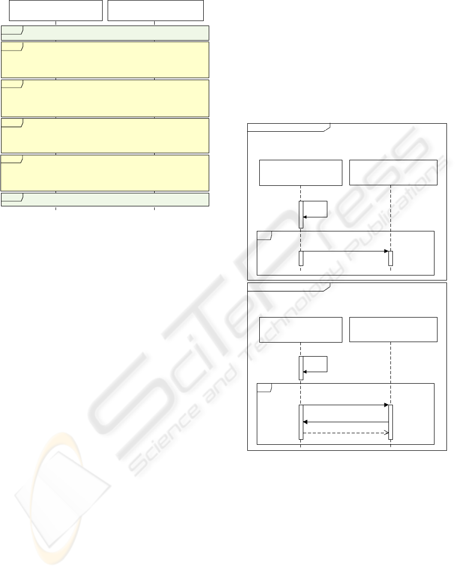
Figure 4 shows the interactions for observer design
pattern where <<PatternEngage>>,
<<PatternInteractionFragment>> and
<<PatternDisengage>> extensions have been
applied. It contains six fragments. There are two
Unique fragments with fragmentRole named
GetState@ObserverDesignPattern and
SetState@ObserverDesignPattern. Two variants
exist for fragmentRole named
UpdateMember@ObserverDesignPattern. This can
be identified by looking at the fragmentType =
Variant tagged value. The two variants each has
fragmentName of ObserverPush and ObserverPull
respectively. Both the fragments have the same
goal, i.e. to update all observers. However the
implementations are different. The designer can
choose between ObserverPush or ObserverPull
EXTENDING UML TO REPRESENT INTERACTION ROLES AND VARIANTS OF DESIGN PATTERN
203
<<PatternRole>>
:CS
{role=”ConcreteSubject@Observer”}
<<PatternRole>>
:CO
{role=ConcreteObserver@Observer}
<<PatternEngage>>
ObserverInteractionAttach
ref
{fragmentRole = “UpdateMembers@ObserverDesignPattern”,
fragmentName = ”ObserverPush”,
fragmentType = Variant}
<<PatternInteractionFragment>>
ObserverInteractionUpdatePush
ref
{fragmentRole = “UpdateMembers@ObserverDesignPattern”,
fragmentName = ”ObserverPull”,
fragmentType = Variant}
<<PatternInteractionFragment>>
ObserverInteractionUpdatePull
ref
{fragmentRole = “GetState@ObserverDesignPattern”,
fragmentName = ”SubjectGetState”,
fragmentType = Unique}
<<PatternInteractionFragment>>
ObserverInteractionGetState
ref
{fragmentRole = “SetState@ObserverDesignPattern”,
fragmentName = ”SubjectSetState”,
fragmentType = Unique}
<<PatternInteractionFragment>>
ObserverInteractionSetState
ref
<<PatternDisengage>>
ObserverInteractionDetach
ref
Figure 4: Observer Design Pattern Interactions with
Extended Information.
method as its tagged value is a variant type. The
actual interaction for these two fragments are shown
in Figure 5. In Figure 5(a), when the
ConcreteSubject is notified, the ObserverPush
method sends the actual data to be updated to the
ConcreteObserver while ObserverPull method
informs the ConcreteObserver on the availability of
data without sending the actual data as shown in
Figure 5(b). The corresponding ConcreteObserver
would then issue a getUpdateData to get the actual
data from the ConcreteSubject. Depending on the
designer problem in a specific problem situation, the
designer may decide which implementation is
suitable to solve the problem he/she is working on.
The advantage or disadvantage of both pull and push
method do depend on what situation it is being used.
More details on different types of observers or
publish/subscriber pattern can be found in the works
in (Eugster et al. 2003).
In the Figure 5 (a), the name of the lifeline CS or
CO can be replaced with the designer’s own domain
name. When the name is replaced, the pattern role
that the lifeline represent will still exist by looking at
the role tagged definition and hence the pattern
information can still be identified. Similarly, the
naming of the fragment
ObserverInteractionUpdatePush, for instance can be
replaced and designers can still see that the fragment
is an ObserverPush variant from the tagged values.
As an example, in an auction, auctioneer may play
the role of the ConcreteSubject and bidder may play
the role of ConcreteObserver. When a new bid has
been notified, the current bidding price are then
updated to all the bidders registered to the auction.
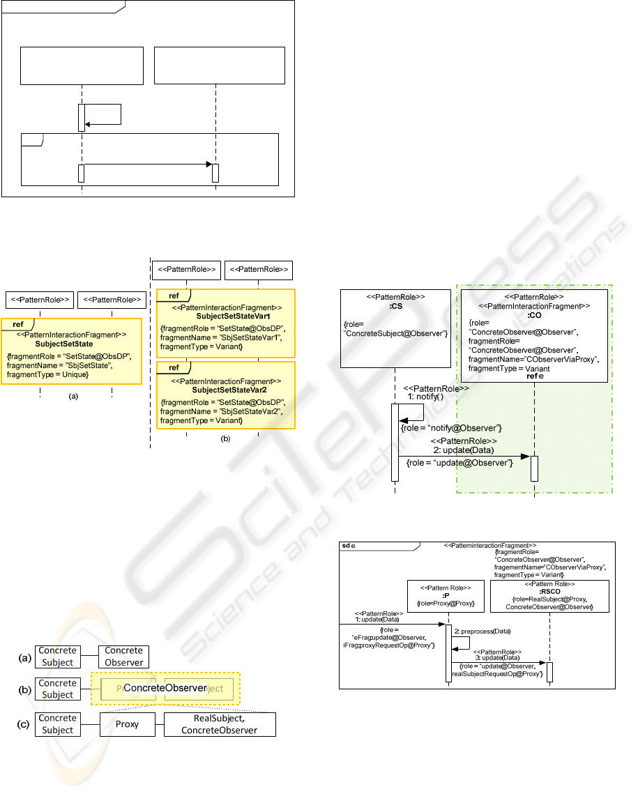
Figure 6 shows part of the interaction where the
naming of the lifeline and messages are replaced
with the designer’s own domain name while
maintaining the pattern role.
When a new variant is discovered for a fragment
and needs be catalogued, the fragmentType can be
changed from Unique to Variant and with a new
fragment added. Figure 7 shows one fragmentRole
SetState@ObsDP changed into two fragments.
(b)
(a)
<<PatternRole>>
:CS
{role=”ConcreteSubject@Observer”}
<<PatternRole>>
:CO
{role=ConcreteObserver@Observer”}
loop
2: update(Data)
<<PatternRole>>
{role = “update@Observer”}
[for each <<ConcreteObserver@Observer>>
1:notify()
<<PatternRole>>
{role = “notify@Observer”}
{fragmentRole=
“UpdateMembers@ObserverDesignPattern”,
fragmentName=”ObserverPush”,
fragmentType = Variant}
<<PatternInteractionFragment>>
sd ObserverInteractionUpdatePush
<<PatternRole>>
:CS
{role=”ConcreteSubject@Observer”}
<<PatternRole>>
:CO
{role=ConcreteObserver@Observer”}
loop
2: update()
<<PatternRole>>
{role = “update@Observer”}
3: getUpdateData()
4: Data
{fragmentRole=
“UpdateMembers@ObserverDesignPattern”,
fragmentName=”ObserverPull”,
fragmentType = Variant}
<<PatternInteractionFragment>>
sd ObserverInteractionUpdatePull
[for each <<ConcreteObserver@Observer>>
1:notify()
<<PatternRole>>
{role = “notify@Observer”}
Figure 5: Observer Design Pattern Interaction Update
Variants; (a) Observer Push (b) Observer Pull.
Although some interactions may be a subtle
variant, having visualised the variant may be able to
help the designer to see which method is suitable to
the designer’s design problem. The current
interaction variants of observer design pattern are
not exhaustive. However additional types of variant
can be added and be specified as
fragmentType=Variant. Due to space constraint the
remaining fragments previously shown in Figure 4
are not presented.
ICSOFT 2010 - 5th International Conference on Software and Data Technologies
204
<<PatternRole>>
:Auctioneer
{role=”ConcreteSubject@Observer”}
<<PatternRole>>
:Bidder
{role=ConcreteObserver@Observer”}
loop
2: updateBid(Price)
<<PatternRole>>
{role = “update@Observer”}
[for each <<ConcreteObserver@Observer>>]
1:notifyCurrentBid()
<<PatternRole>>
{role = “notify@Observer”}
{fragmentRole=
“UpdateMembers@ObserverDesignPattern”,
fragmentName=”ObserverPush”,
fragmentType = Variant}
<<PatternInteractionFragment>>
sd UpdateBidder
Figure 6: Interaction with Changes to the Lifeline and
Message Names.
Figure 7: (a) One Unique Fragment for SetState@Obs DP
(b) Two Variant Fragments for SetState@ObsDP.
One example of variant of the lifeline is when a
pattern role ConcreteSubject in an observer design
pattern interacts with pattern role ConcreteObserver
via another pattern. Figure 8(b) shows a variant that
can occur between ConcreteSubject and
ConcreteObserver. Interaction in Figure 8(b) can be
represented in UML sequence diagram as shown in
Figure 9.
Figure 8: (a) ConcreteSubject interacts with
ConcreteObserver directly; (b) ConcreteSubject interacts
with ConcreteObserver that is composed of other patterns;
(c) ConcreteSubject interacts with the decomposed
ConcreteObserver from (b).
In Figure 9 there exist a variant on the
ConcreteObserver lifeline with fragmentRole of
ConcreteObserver@Observer. The actual
interaction refers to sequence diagram in Figure 10.
In Figure 10 the message connecting from the gate
have two role i.e. The value
eFrag:update@Observer represents the external
pattern role from which the message originates from
whereas iFrag:proxyRequestOp@Proxy represents
the pattern role in the current sequence diagram. As
can be seen from the diagram, the message is
preprocessed via a proxy design pattern before
finally sent to RSCO lifeline. One example of a
preprocess operation could be checking the data for
consistency and logging of messages before sending
to the real subject. RSCO lifeline plays a composite
role where it plays the role of RealSubject at proxy
design pattern as well as ConcreteObserver at
observer design pattern.
Figure 9: HPFV on ConcreteObserver Lifeline.
Figure 10: Interactions referenced from the
ConcreteObserver Lifeline.
4 DISCUSSION
Using UML profile for extension has been done in
various domains and fields such as in architecture
(Kandé & Strohmeier 2000), mobile system (Grassi,
Mirandola & Sabetta 2004) and Graphical User
EXTENDING UML TO REPRESENT INTERACTION ROLES AND VARIANTS OF DESIGN PATTERN
205

Interface (Blankenhorn & Jeckle 2004). Works on
the visualization of design pattern in composition
have been conducted by (Dong, Yang & Zhang
2007). The authors use tagged pattern annotation as
a method of visualizing design patterns in UML
Class diagram and UML communication diagram.
Its approach is through specifying three stereotypes
extending metaclass of class, operation and attribute.
Current approach on pattern role is similar to the
approach on representing pattern role information
via profile. In contrast, the current method
introduced a single stereotype PatternRole to
represent the pattern information on both the lifeline
and message. Also the current work focused on the
UML sequence diagram and extends the UML
interaction fragment to enable defining and viewing
the role and variant of design pattern interaction
which was not addressed in (Dong, Yang & Zhang
2007). In specifying patterns in the interaction
diagram, works in (France et al. 2004) specify
design patterns via Interaction Pattern Specification.
The approach is through extending the metamodel
itself. The main aim is to specify design patterns and
did not focus on defining the variants in a design
pattern. Work in (Noble 1998) defines the variant of
design pattern as a refinement of another pattern,
and the current work views the variant as the
interaction alternatives. Variant of interaction in
design patterns is also viewed as at difference
abstraction level than the variability in software
product line (Pohl & Metzger 2006) as generic
design patterns spans across different domain and
application engineering. The extension introduced
for variant differs from alt in sequence diagram
where alt is more for control flow and the extension
for variant introduced provides referencing and
decomposition for fragments and lifelines.
5 CONCLUSIONS
This paper presented an approach to represent
pattern interaction role and variants of design pattern
via extension to UML sequence diagram. The
extensions are made to Interaction, InteractionUse,
Lifeline and Message metaclasses. Two ways of
fragment variant, HPFV and VPFV have been
introduced to characterise the growth direction of the
fragment variant and then applied to the observer
design pattern. Further work includes providing a
case study of defining variant for more design
patterns retrieved from a design pattern catalogue
tool. Also needed to be worked is the specification
of the constraints on Interaction and InteractionUse
with Object Constraint Language (OMG 2006)
where the tagged values need to be consistent. The
proposed method assists in the cataloguing the
variety of design patterns as well as retrieval of
behavioural information and its variant in a visual
design modeling tool. Furthermore, it provides
support for scenario views before adapting design
patterns for a design via transformation
automatically. A prototype is underway for a
graphical design pattern UML tool with the
proposed extension for cataloguing, retrieval and
adaptation of design patterns using Model
Development Tools, MDT (Eclipse 2010). Future
work includes empirical studies on the improvement
in design activities using the tool support with the
presence of the proposed extension and checking of
the semantics of design patterns during adaptation.
ACKNOWLEDGEMENTS
The authors would like to thank anonymous
reviewers for their insightful comments and partial
fund support from University of Malaya.
REFERENCES
Agerbo, E. & Cornils, A. 1998, 'How to preserve the
benefits of Design Patterns', ACM SIGPLAN Notices,
vol. 33, no. 10, pp. 134-43.
Blankenhorn, K. & Jeckle, M. 2004, 'A UML Profile for
GUI Layout', NODe 2004, vol. LCNS 3263, pp. 110-
21.
Budgen, D. 1999, 'Software Design Methods: Life Belt or
Leg Iron?', Software, IEEE, vol. 16, no. 5, pp. 133-5.
Software Design, Second edn, Pearson Education Limited,
Essex, England, 2003.
Dong, J., Yang, S. & Zhang, K. 2007, 'Visualizing Design
Patterns in Their Applications and Compositions',
IEEE Transactions on Software Engineering, vol. 33,
no. 7, pp. 433-53.
Eclipse 2010, Model Development Tools (MDT), <http://
www.eclipse.org/modeling/mdt/>.
Eugster, P. T., Felber, P. A., Guerraoui, R. & Kermarrec,
A-M. 2003, 'The Many Faces of Publish/Subscribe',
Computing Surveys (CSUR), vol. 35, no. 2.
France, R. B., Kim, D-K., Ghosh, S. & Song, E. 2004, 'A
UML-Based Pattern Specification Technique', IEEE
Transactions on Software Engineering, vol. 30, no. 3,
pp. 193-206.
Gamma, E., Helm, R., Johnson, R. & Vlissides, J. 1995,
Design Patterns: Elements of Reusable OO Software,
Addison-Wesley.
Grassi, V., Mirandola, R. & Sabetta, A. 2004, 'A UML
Profile to Model Mobile Systems', UML 2004.
ICSOFT 2010 - 5th International Conference on Software and Data Technologies
206

Kandé, M. M. & Strohmeier, A. 2000, 'Towards a UML
Profile for Software Architecture Descriptions', UML
2000.
Lethbridge, T. C. 2000, 'What knowledge is important to a
software professional?', Computer, vol. 33, no. 5, pp.
44-50.
Noble, J. 1998, 'Classifying Relationships between Object-
oriented Design Patterns', in Australian Software
Engineering Conference, 1998, pp. 98-107.
OMG OMG Model Driven Architecture, <http://
www.omg.org/mda/>.
'Object Constraint Language OMG Available
Specification Version 2.0', 2006.
'OMG Unified Modeling Language (OMG UML),
Superstructure, V2.1.2', 2007.
Pohl, K. & Metzger, A. 2006, 'Variability Management in
Software Product Line Engineering', ICSE' 06, pp.
1049-50.
EXTENDING UML TO REPRESENT INTERACTION ROLES AND VARIANTS OF DESIGN PATTERN
207
