
COMMON SERVICES FRAMEWORK
An Application Development Framework
Jeanette Bruno, Michael Kinstrey and Louis Hoebel
Computing and Decision Sciences GE Global Research, Niskayuna, NY, U.S.A.
Keywords: Frameworks, Architecture, Design patterns.
Abstract: The Common Services Framework (CSF) is developed by GE’s Global Research Center (GRC) as a design
pattern and framework for application development. The CSF is comprised of a set of service-oriented
API’s and components that implement the design pattern. GE GRC supports a wide diversity of R&D for
GE and external customers. The motivation was for a reusable, extensible, domain and implementation
agnostic framework that could be applied across various research projects and production applications. The
CSF has been developed for use in finance, diagnostics, logistics and healthcare. The design pattern is an
extension of the Model-View-Controller pattern and the reference implementation is in Java.
1 INTRODUCTION
Developed at GE’s Global Research Center (GRC),
the Common Services Framework (CSF) is a design
pattern and framework for application development.
The CSF is comprised of a set of service-oriented
framework API’s and components that implement
the design pattern. GE GRC supports a wide
diversity of R&D for GE and external customers.
The motivation is for a reusable, extensible, domain
and implementation agnostic framework that could
be applied across the research projects and
production applications. The CSF has been
developed for use in finance, diagnostics, logistics
and healthcare.
The CSF emerged from the desire to stop
“reinventing the wheel” with every new software
application. Most software projects start by “lifting”
ideas, patterns, and functionality from past projects.
Since most project teams consist of a new and
sometimes changing group of people, the influx of
differing experience needs to be merged and
organized for each new project. New projects tend
towards unique, if somewhat similar, designs where
the uniqueness of the design does not typically
improve the product. The unique features often
detract from the design since they make the lifecycle
maintenance more expensive, either in terms of
integration with other projects or extensible in its
own right.
The key motivations for the Common Services
Framework are reuse, interoperability and design for
maintainability. By reuse we mean the use of
existing software or software knowledge, to build
new software applications and systems. Although
many software development projects reuse concepts
and code from previous projects it is usually done ad
hoc. The existing designs and software code cannot
be “lifted systematically” nor can new contributions
be made back to the original code base in a
structured way. Frameworks such as Java’s Spring
[http://www.springsource.org] and Hibernate
[https://www.hibernate.org] promote more organized
reuse in the functional areas they cover, but software
applications cover a wider range of functionality
beyond the focus of these frameworks.
Designing software systems to withstand the
inevitable changes is a constant challenge.
Development and deliverable schedules often
conflict with the time needed to predict change and
design appropriate solutions to manage change.
Most design teams try to balance the effort, but
aggressive schedules and looming deadlines often
result in maintainability being compromised.
The CSF fosters reuse by defining a common
pattern and framework that can be applied across
any software project. The CSF pattern is based on
common design patterns prevalent in the industry
today and is positioned for agility and longevity. It
covers the routine aspects of functionality in (nearly)
every software project and has extension areas for
the project-specific nuances. Adopting the CSF
pattern provides a solid foundation for each new
project, allowing for quick focus on domain-specific
project aspects.
87
Bruno J., Kinstrey M. and Hoebel L. (2010).
COMMON SERVICES FRAMEWORK - An Application Development Framework.
In Proceedings of the 5th International Conference on Software and Data Technologies, pages 87-94
DOI: 10.5220/0003011900870094
Copyright
c
SciTePress

The CSF design pattern is based on the common
Model-View-Controller pattern and incorporates
existing frameworks including Spring, Struts and
Java Server Faces (JSF). CSF provides standard
approaches to their use and promotes encapsulation
of the provided functionality thus reducing
dependency on them. A key tenet of the CSF is to
build software solutions with well-defined and well-
encapsulated functional boundaries for the various
components in the solution. This characteristic
supports replacing existing components with new
versions as the industry evolves, thus avoiding
vendor or component “lock-in”.
This paper describes the CSF, how it is used and
its relationship with other well-known frameworks.
Section 2 discusses the concepts of design patterns,
frameworks and architecture. Section 3 provides
specific details on the CSF. Section 4 presents some
of the benefits from productivity and risk reduction
and Section 5 wraps up with conclusions and next
steps.
2 ARCHITECTURES, DESIGN
PATTERNS, AND
FRAMEWORKS
In the prior section, the terms design pattern and
framework are used as if an unambiguous meaning
existed. Unfortunately, the meanings very often
differ from person to person. In an effort to reduce
any confusion with respect to this paper, the
following subsections defining our meaning of
design patterns, frameworks, and architecture.
2.1 Architecture
Architecture is a thing’s or artifact’s fundamental
underlying design and its structure
[http://dictionary.reference.com/browse/architecture]
A software system’s architecture describes the
components in the system, how they interact with
each other and with elements outside the system. It
is important to realize that “the architecture” of an
application is an abstract notion. One cannot point to
a single document and say “that is the architecture”.
Instead views are used to show specific perspectives
of the design to convey the architecture.
Just as architectural drawings for a residential
home show different views of the structure, software
architectures are typically described using a number
of views of the system. Functional, component,
hardware, behavioral, and user interaction are
common views used to describe a software system’s
architecture. Functional or logic views describe how
the computation embodied in the system is
decomposed into functional blocks. Component
views describe the software components that are
developed or used in the implementation. Hardware
views show the hardware used to deploy the system
and how the various functional blocks and
components are distributed on the hardware.
Behavioral views describe the computational flows
through the system. User interaction views show
how the users interact with the system. Finally, data
views show how the system manages its data. Other
views are also used, as appropriate. Some views,
such as a functional view and the component view
are commonly used, but there is no standard set of
views that all software systems use to document
their architecture.
To summarize, the architecture of an application
is the (abstract) definition of the form and function
of the application. Each application will have its
own architecture. It may be the case that multiple
systems have similar architectures, and thus share
common architectural views for some aspect(s) of
the architecture but, unless multiple systems do
exactly the same thing with the same structure, each
will have some unique aspect(s) to its architecture.
2.2 Design Pattern/Architectural
Pattern
A design pattern is a formal way of documenting a
solution to a design problem in a particular field of
expertise
[http://en.wikipedia.org/wiki/Design_pattern_(comp
uter_science)]. It is a common pattern or structure
that is reused across multiple software systems.
Many identified and well-known design patterns are
commonly used in software system design. Some of
the well-known design patterns with respect to
functional encapsulation include: factory
mechanisms, object managers, loggers, adapters,
mediators and GUI patterns. Others, such as web
services, distributed, federated and cloud patterns
are with respect to the deployment features of the
components. Design patterns establish common
architectural features across the applications that
adopt them.
The term design pattern started becoming widely
used around the time the book Design Patterns by
the “Gang of Four” was published [Gamma et al,
1995]. Before this, design patterns existed but prior
to adopting the term, design patterns were not
recognized and explicitly called out as design
patterns. Perhaps the most commonly known design
pattern is the Model-View-Controller (MVC) pattern
[http://en.wikipedia.org/wiki/Model_view_controller
ICSOFT 2010 - 5th International Conference on Software and Data Technologies
88
]. The MVC pattern was in use well before the
publication of [Gamma et al, 1995] and was
commonly referred to as an architecture, or
architectural pattern.
2.3 Framework
A software framework provides implemented
functionality and structure that can (generically) be
used as-is or overridden, extended and specialized to
provide specific functionality. Frameworks typically
implement targeted areas of functionality that are
common to many systems. Spring
(http://www.springsource.org), J2EE
[http://java.sun.com/j2ee/overview.html], .NET
[http://msdn.microsoft.com/en-
us/library/zw4w595w(VS.71).aspx], JSF
[http://java.sun.com/javaee/javaserverfaces/overvie
w.html], Struts
[http://struts.apache.org/1.0.2/userGuide/introductio
n.html], Hibernate [https://www.hibernate.org] and
AJAX [http://glm-ajax.sourceforge.net] are
commonly known and used frameworks.
Frameworks carry specific APIs for interacting
with them. These APIs establish the design pattern
for interfacing with the application components.
2.4 Architectures, Design Patterns,
Frameworks, and the CSF
As we have stated, design patterns define common
structural patterns (design) for a software
application, frameworks provide standard
functionality (implementation) and thus a common
design pattern for the framework’s area of focus, and
the architecture of an application includes a
description of the design patterns and frameworks
used in the application.
Given these definitions, the CSF is a framework
that defines a comprehensive design pattern that
covers all the functional aspects of a software
application.
The design pattern embodied by the CSF is the
most important aspect of the CSF. The CSF extends
and refines the MVC design pattern and is not a new
design pattern. The CSF is derived by canvassing
and combining existing, commonly used design
patterns. Existing design patterns target specific
functional areas of an application, but do not provide
a comprehensive application pattern. The CSF
defines focused sub-tiers of functionality within the
MVC pattern. Where appropriate, these sub-tiers
correspond with the design patterns in existing
frameworks.
3 OVERVIEW OF THE CSF
CSF uses the MVC design pattern as valuable
guidance for segregating Model, View and
Controller functionality from each other. If we
simply ended there, a great deal of chaotic
organization would still exist within each of these
layers. The CSF refines the MVC concepts to
explicitly extend and segregate multiple layers for
shared application functionality that cannot be easily
pigeonholed into one of the MVC layers. The result,
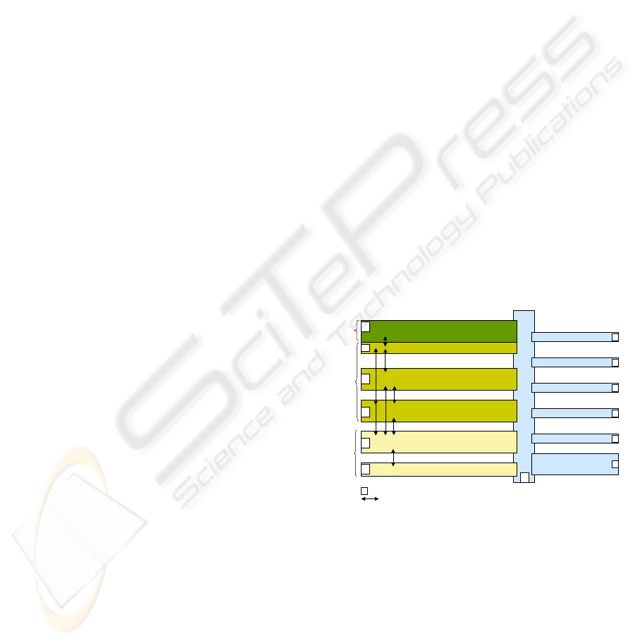
shown in Figure 1 CSF Design Pattern below,
presents the CSF design pattern and illustrates its
relationship to the MVC pattern. The left-most, or
Application Domain, tiers of the CSF design pattern
refine the MVC layers into five (5) more focused
functional areas. These are: Executive Control,
Application Control, Domain Modules, Information
Model and Data I/O. The right-most tiers explicitly
call out the more generic functionality that tends to
span the MVC tiers.
Two sets of criteria motivate establishing
refinements to the MVC pattern and boundaries to
the common areas. The first criterion is functional
encapsulation to minimize the impact of changes to
the system. The MVC pattern of model, view, and
controller establishes an initial pattern for dividing
applications into tiers that insulate functionality
from the typical changes to an application.
Co nt e xt / f ac t o r i es
Application Control
Domain Modules
Information Model
Dat a I/ O
model
view
control
Application Domain Utility Domain
Configuration
com.ge.grc.csf.app.domain
com.ge.grc.csf.infom odel
com.ge.g rc.csf .mod el .io
com.ge.grc.csf.app.control
com.ge.grc.csf.app.exec.action
com.ge.gr c.csf.app.exec.f or ms
com.ge.grc.csf.context
com.ge.g rc.csf .fac tory
com.ge.grc.csf.util.logging
com.g e.gr c.c sf.ut il.secu rit y
com.ge.grc.csf.util.logging.metrics
logging
securit y
metrics
communications
protocol
notification
reporting
com.ge.gr c.csf.util.notification
com.ge.gr c.csf.util.reporting
Dominant interaction paths (other pat hs discour aged)
Executive Control
Figure 1 CSF Design Pattern.
CSF refines the control aspects to encapsulate and
discriminate between the top layer “GUI-based”
control, a middle tier “Application Control” and
middle tier “Domain Modules”. CSF also refines the
MVC model layer by encapsulating and
discriminating between an “Information Model” and
“Data I/O” layers. And finally CSF explicitly calls
out the standard interaction paths between the layers.
The second criterion for the refinements is
compatibility with concepts already established by
available industry frameworks such as Spring
COMMON SERVICES FRAMEWORK - An Application Development Framework
89

[http://www.springsource.org], Hibernate
[https://www.hibernate.org], and Log4J
[http://logging.apache.org/log4j/1.2/index.html].
There is no compelling reason to “reinvent the
wheel”, as these frameworks already establish well-
known and proven design patterns.
As described, the Application Domain tiers in
Figure 1 represent encapsulations that insulate each
other from the typical changes encountered as a
software application is maintained. At the core are
the domain modules, which are specialized
functional blocks that give the application its
behavior. By having these concepts with their own
defined boundaries, changes to core domain specific
computations in the application should have minimal
effect on other areas of the application. Any ripple
effects should be confined to the interaction paths
defined in the image. When the control flow is
separated from domain computations, adding new
computations should only affect the part of the
control that invokes the computation and the related
aspects of information production and consumption.
If other ripple effects exist, they remain localized to
the specific presentation and data persistence layers
dealing with the new or altered information.
The information model tier provides a buffer
between the rest of the application and the data
persistence (read/write) interfaces. This allows
persistence structures (database schemas, file
structures, and/or sensor inputs) to change without
disrupting the rest of the application.
The Utility tier (including context/factories) is
derived based on existing framework concepts. As
we canvassed existing frameworks, the pattern
shown above emerged. When we took a step back
and looked at the pattern, we agreed that these were
functional areas that tended to be used by all of the
left-most MVC tiers, and that this definition of
layers provided a good description of the functional
boundaries and characteristics of the right-most tier.
The “Utility Domain” tiers of Figure 1 are
comprised of frameworks that encapsulate functional
areas that could be used by any of the “Application
Domain” tiers in the diagram. Each functional area
can be thought of as a general handler that is
responsible for coordinating and implementing the
underlying functionality. For example, many
components of an application will want to utilize the
logging functionality. Various application
components may require different logging behaviors
or even multiple logging mechanisms (e.g. file
logging for general information and console logging
for the most important information). The CSF
framework provides a common API to these
mechanisms. This approach isolates the
implementation details from the invoking
components. The same can be said for security,
where different security mechanisms may be needed
at the different tier levels. The security API provides
the interface to the handler, and the implementation
details are isolated from the invocation points. The
same holds for metrics and the other utility domain
components identified. These commonly used
features are grouped together as “ Domain Utilities”.
In order for the tiers and components to access
the utility domain components and potentially share
the utilities between tiers, the Context and Factory
patterns are utilized. “Application Domain” tier
components request the utility components via these
patterns, where the discovery and instantiation
operations occur. The requestors merely expect an
instance of the component to be returned. The
Context and Factory patterns enable plug-and-play
flexibility and configurability without needing to
modify code. This allows applications to change
utility behaviors by merely changing configuration
options. An example is replacing a console-based
logger with a file-based logger. The application
component that needs a logger requests the logger
mechanism from the context. Based on the
application’s configuration, the context will return
one type of logger vs. another.
3.1 Using CSF for Application Design
Following the CSF design pattern will result in a
speed up of the design process, sometimes dramatic.
Some initial CSF projects show savings of 25% for a
4 week design phase in a small project and up to
85% code reuse for a larger project, with a similar
design and existing domain functionality.
Once the top-level requirements for a project
have been established, the designers simply start
defining the functional blocks for the solution
application in relation to the CSF tiers. Working
through the Functional tiers the designers can focus
on the domain-specific aspects of the solution,
putting the right-hand more general concepts
mentally “off to the side”. The predefined tiers help
guide the designer through developing the functional
architecture of the solution. At first the user simply
outlines the functional components for the solution,
following the CSF’s recommended functional layers.
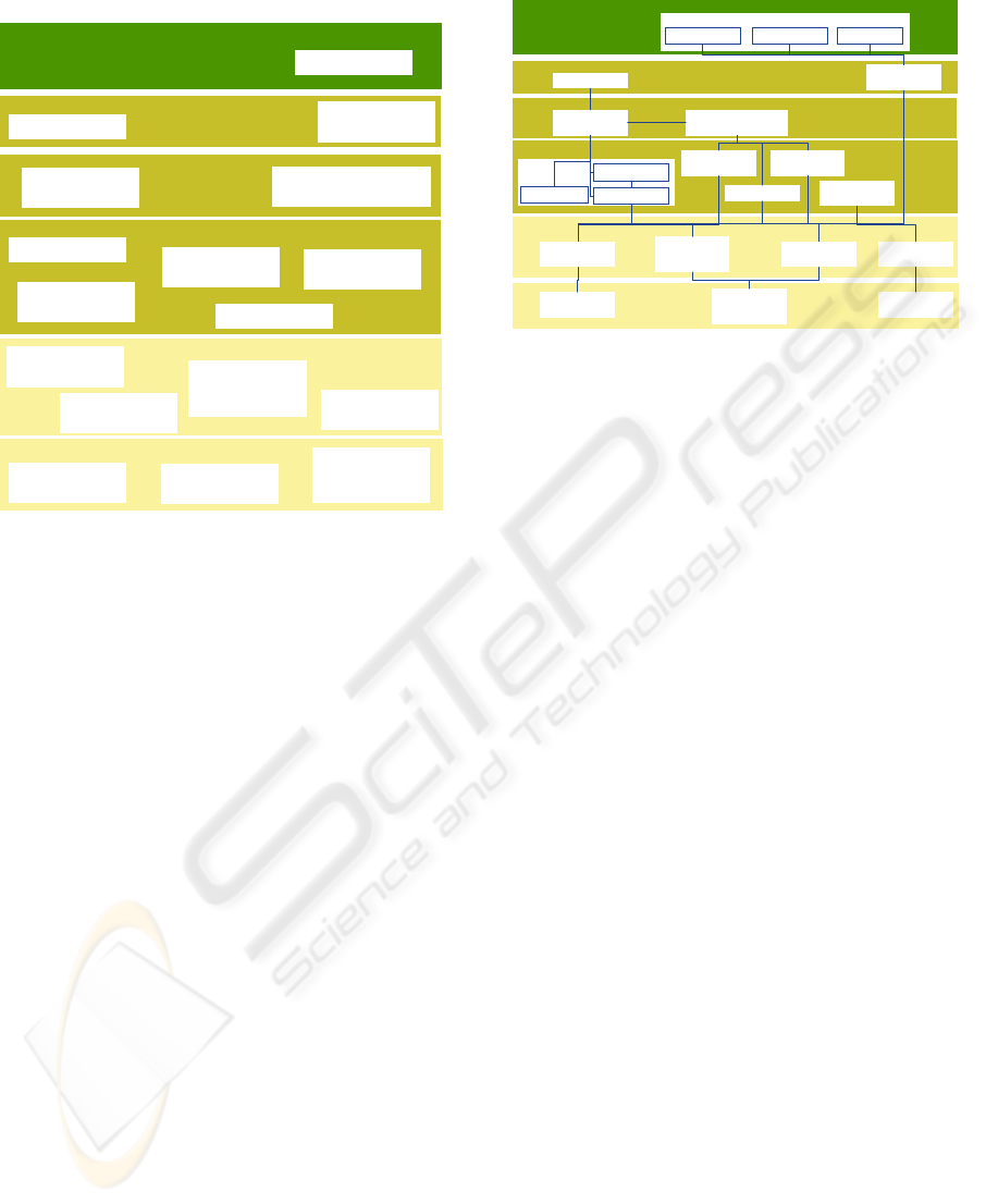
An example of a resulting design is shown in Figure
2 Product Monitoring Functional Components.
Once the key functional components have been
identified, the associations and interactions between
the components and detailed refinements of the
components are defined as shown in Figure 3
Product Monitoring Functional Architecture.
Graphical images are then produced that use a
consistent visual representation and layout of the
CSF tiers to communicate the top-level design of the
system. With this approach designers simply follow
ICSOFT 2010 - 5th International Conference on Software and Data Technologies
90
Product Monitoring Application
Fu n c t i o n al v i ew
Aler t r esponse
Parsing control
flow
Health assessment
control flow
Informat ion Model
Domain Models
Applicat ion Control
Dat a I/ O
Web-base alert
interactions
Message Parser
Healt h
assessment
Dat a
Manipulat ion
Prognostics
Advisory
Gen er at i on
Pa r si ng
Performance
Information
Product
Configuration
Informat ion
Product Healt h
Informat ion
Performance
Information I/O
Product Advisory
Information
Pr od uc t
Configuration
and Health I/O
Product Advisory
I/O
Executive Control – contr ol layer
Executive Control – view layer
Figure 2 Product Monitoring Functional Components.
the pattern for functional encapsulation cutting the
design time in many cases in half or even more. In
addition, using a consistent pattern for the functional
tiers and representation helps reviewers and
developers new to the project come up to speed
more quickly.
The functional encapsulation and well-
established interaction patterns between the
functional tiers allow the effort to be distributed to
sub-teams and the refinement of the design and
implementation of the solution can then proceed in a
more orderly and efficient manner.
3.2 Using CSF for Application
Development
The CSF pattern also promotes implementing the
solution with a package structure that corresponds
with the functional tiers. This provides developers
with the knowledge needed to organize their code
and for others to find the various functional pieces.
The CSF also provides a number of implemented
functional pieces that can be reused across
applications. The majority of the CSF functionality
covers standard behavior in the Utility Domain
(since these tiers tend to be independent of domain
behavior). Most of the implemented functionality
simply wraps standard capabilities that have already
been published in open source (example: the Spring
Context mechanism [http://www.springsource.org/
Product Monitoring Application
Functional view
Alert r esponse
Parsing control
flow
Heal t h assessment
control flow
Information Model
Domain Models
Applicat ion Contr ol
Data I/ O
Web-base alert
interactions
Message Parser
Per f o r ma nc e
Information
Product
Configuration
Informat ion
Product Healt h
Informat ion
Per f or m a nc e
Informat ion I/ O
Product Advisory
Informat ion
Product
Configuration
and Health I/ O
Product Advisory
I/O
Executive Control – control layer
Executive Control –view layer
Fleet Summary Unit Summary
Adhoc Reports
Heal t h
assessment
Dat a
Manipulation
Prognostics
Advisor y
Gen er a t i o n
Pa r s i ng
Message Type
Message
1
Pa r s e
…
Message
n
Pa r s e
Figure 3 Product Monitoring Functional Architecture.
and the Hibernate ORM
[https://www.hibernate.org]).
If a generic pattern is established for application
domain behavior (such as with the OSA-CBM
[http://www.mimosa.org] pattern for implementing
condition-based maintenance analysis), a higher
order framework can be defined that extends the
base CSF pattern with the domain-specific pattern.
3.3 CSF, SOA and Distributed
Architectures
The articulation of the CSF design pattern often
raises questions regarding the CSF’s relationship to
other design patterns and frameworks. The general
answer is that CSF does not compete with the other
patterns. Instead, it incorporates and combines the
most prevalent patterns into a comprehensive pattern
that covers all aspects of a software application. The
following sections describe the CSF’s relationship to
some of the more common patterns and frameworks
in use today.
A Service Oriented Architecture (SOA) calls for
segmenting application functionality into blocks that
can be exposed as services so they can be reused in
other applications and/or distributed across various
pieces of hardware. There are many mechanisms for
exposing/deploying and connecting to a service.
Perhaps the most common mechanism is via a web-
based interface such as REST
[http://en.wikipedia.org/wiki/Representational_State
_Transfer] or SOAP [http://en.wikipedia.org/
wiki/SOAP]. Other non-web based connection
protocols exist such as JMS
[http://java.sun.com/developer/technicalArticles/Eco
mmerce/jms/index.html]. The CSF design pattern
promotes the SOA concept.
COMMON SERVICES FRAMEWORK - An Application Development Framework
91

In order to maximize the usefulness of a service,
the design must find the right balance of
encapsulation and generalization of functionality.
Typically, as the behavior becomes more complex,
its usefulness becomes more focused and only
applicable to specific situations. The services that
experience broader use tend to provide general
functionality and are implemented to use input
parameters to configure and tailor the computation
based on the service user’s needs.
The CSF pattern promotes separating domain
logic from control flow and data i/o. This
encapsulation pattern tends to produce domain logic
and data i/o services. It should be noted that services
can be achieved with the tighter coupling or
intermingling of these areas of functionality, but as
mentioned above, as the underlying functionality in
a service become more complex, the opportunities to
reuse the service decrease.
A key concept promoted in the CSF pattern is
the separation of the connection protocol from the
underlying functionality, and use of dependency
injection for runtime assembly of the desired
connection mechanisms. With this approach a single
implementation of a service can be deployed using
various connection protocols thus achieving even
more reuse. When the service is initially developed,
it is written as a well-encapsulated set of
functionality and exposed using a tight coupling
mechanism such as a plain-old-java-object (POJO).
The invoker of the service merely calls a method on
the object. Once the module’s API is established,
two wrappers can be written for the connection
protocol. One wrapper will expose the module and
desired methods via the desired protocol as a service
on the server machine. The other wrapper will be
injected at runtime on the client (calling) platform to
establish the connection (again using the desired
protocol) with the module that is now deployed as a
service. To the invoker of the service, the calling
mechanism is the same – it appears to be a local
method call. The client wrapper mimics the API,
instead passing the method parameters through the
communication protocol to the remote service.
Return values are passed back in the same manner.
By following these layers of encapsulation, a single
instance of a module can be exposed via multiple
connection protocols.
Following this design and development pattern
also simplifies and speeds up the development
process. A standard pattern, with “cookbook”
instructions and examples for wrapping and
deploying modules as services is provided in the
CSF documentation. With this, the developer can
focus on getting the desired functionality working,
and then simply follows the instructions for
exposing the module as a service. Having a standard
pattern for achieving the connection protocol
reduces the risk of errors in this area of the code,
makes it easier for other developers to understand
the code, and speeds up the development time.
3.4 CSF and Spring
The CSF is not intended to replace Spring. A
framework, by the nature of its APIs, defines a
design pattern. CSF is a design pattern that includes
the Spring design pattern. The CSF adds a number
of layers that are not provided for in the Spring
framework (information model, communication
protocol, metrics, reporting, etc.), but it otherwise
embodies the main Spring concepts such as
dependency injection, data i/o, and the security
layer. Spring’s embodiment of JSF and Ajax also
correspond with the form and action sub-tiers of the
executive control layer.
In fact, many aspects of the APIs in the CSF
were derived from the Spring Framework
functionality. Some of the reference implementation
components directly use the Spring functionality and
the CSF recommends using these modules whenever
possible. The CSF does provide alternate (and
typically less functional) implementations to the
Spring components. The main reason for providing
these alternatives is for situations where full control
of all the source code is required for testing or
certification requirements. Additionally, simpler
versions of the functionality may be entirely
adequate.
One of the CSF’s secondary benefits is that it
provides a lightweight introduction to Spring and its
framework code. The reference implementation
components, the training modules, and test code all
provide samples of how to use Spring.
3.5 CSF, 2-tier, and 3-tier
Architectures
The often used concepts of 2-tier and 3-tier
architectures are sometimes misused and confused
concepts. At their most basic level, they address
segmentation of functionality into two or three main
areas. A 2-tier architecture most often refers to
applications whose functionality is segmented into a
client-server distribution. Such applications typically
have the GUI functionality on a client machine and
the rest on a server machine. The term 3-tier
architecture is often applied to those applications
that have been built with the MVC pattern.
Unfortunately, the terms 2-tier and 3-tier are very
general descriptions and it is not uncommon for
applications to have their own “custom” definition
of the split between the tiers. For instance another
ICSOFT 2010 - 5th International Conference on Software and Data Technologies
92

definition of 2-tier is to segment data i/o from the
rest of the application.
The CSF does not conflict or compete with these
tier concepts. Rather, it extends encapsulated
functionality to an N-tier model.
4 PRODUCTIVITY AND RISK
REDUCTION
Adopting a common design pattern across software
applications has a huge positive impact on the
development and maintenance of the applications.
As we have described, the development teams do not
have to reinvent the routine aspects of new
applications. They are able to immediately focus on
the special nuances of that project. Nor would
maintenance teams need to “come up to speed” on
custom application designs as all the projects have a
similar structure. They would already understand the
layout of the code and, more importantly, the
common pattern establishes guidelines for changing
the code.
A commonly used analogy is in the residential
home construction field when one compares the time
and costs of building a custom house to the time and
cost of building houses in a development where
multiple copies of the same design are being built.
The custom homes are by far more expensive to
build (both in time and money). In addition, custom
homes may turn out to be less appealing in reality
than they were on the architect’s drawings. This
doesn’t happen with homes in a development
neighborhood, because we don’t have to rely on
architecture drawings to understand what the home
would look like. We can simply look at one of the
homes that already exists to understand what a new
one would look like.
The analogy continues to the long-term
maintenance aspect. Making changes to any home
carries a certain amount of risk because many details
of the construction are hidden behind the exterior
decorations. Most times these details only become
apparent as the changes are being made. Many home
remodelling and maintenance efforts have to adjust
their plans as they go because they encounter
unexpected “features” as they open up walls. With
development homes, if common contractors are used
across multiple homes, these contractors will be
more familiar with the structures and the risk of
finding surprise “features” is reduced.
The benefits of a using a common pattern also
extend to preventing code structure from decaying
into a unorganized, tangled mess. As the code is
being maintained, if the maintenance efforts adhere
to the design pattern, the code will not evolve into
your typical “spaghetti” or “ball of mud” anti-
pattern.
5 CONCLUSIONS AND NEXT
STEPS
This paper describes a design pattern and reference
implementation that provides a strong framework
and methodology for application development. The
CSF framework provides benefits of consistent look
and feel for code development, application
architecture and code structure. The framework
encourages and enables reuse by design and
extensions of existing domain areas as well as
supports forays into new domain application spaces.
Finally, applications have been built using the CSF
across domains such as Monitoring and Diagnostics,
Maintenance Estimation for Service Contracts, as
well as Logistics and Text Processing. The approach
has proven to be both cost effective and successful.
Our immediate goal is to extend the core reference
implementation and accomplish integrations of CSF-
based applications with non-CSF applications,
including extensions into the space of embedded
applications.
ACKNOWLEDGEMENTS
We acknowledge the thoughtful contributions of
Julian Chultarsky, Sumita Desai, Helena Goldfarb,
Marc Laymon, Iassen Hristov, and Bowden Wise
without which the CSF would not be as robust as it
is today. We also thank Robert Donaldson and John
Shorter for championing this work and its adoption
within the General Electric Company.
REFERENCES
AJAX, accessed Feb. 25, 2010, <http://glm-
ajax.sourceforge.net>
Dictionary.Com, accessed Feb. 25, 2010,
<http://dictionary.reference.com/browse/architecture>
Gamma, Erich; Richard Helm, Ralph Johnson, and John
Vlissides, 1995. Design Patterns: Elements of
Reusable Object-Oriented Software. Addison-Wesley,
NY
Hibernate, Relational Persistence for Java and .NET,
accessed Feb. 25, 2010, <https://www.hibernate.org>
Jakarta Project: Struts, accessed Feb. 25, 2010,
<http://struts.apache.org/1.0.2/userGuide/introduction.
html>
COMMON SERVICES FRAMEWORK - An Application Development Framework
93

Logging Services, LOG4J, accessed Feb. 25, 2010,
<http://logging.apache.org/log4j/1.2/index.html>
Mimosa, OSA-CBM, accessed Feb. 25, 2010,
<http://www.mimosa.org>
MSDN, Overview of the .NET Framework, accessed Feb.
25, 2010, <http://msdn.microsoft.com/en-
us/library/zw4w595w(VS.71).aspx>
Oracle, Sun Developer Network (SDN), Getting Started
with Java Message Service (JMS), accessed Feb. 25,
2010,
<http://java.sun.com/developer/technicalArticles/Eco
mmerce/jms/index.html>
Oracle, Sun Developer Network (SDN), Java 2 Platform,
Enterprise Edition (J2EE) Overview, accessed Feb. 25,
2010, <http://java.sun.com/j2ee/overview.html>
Oracle, Sun Developer Network (SDN), JavaServer Faces
Technology Overview, accessed Feb. 25, 2010,
<http://java.sun.com/javaee/javaserverfaces/overview.
html>
Spring Source Community, accessed Feb. 25, 2010
<http://www.springsource.org>
Wikipedia: Design Pattern (computer science), accessed
Feb. 25, 2010,
<http://en.wikipedia.org/wiki/Design_pattern_(comput
er_science)>
Wikipedia: Model-View-Controller, accessed Feb. 25,
2010
<http://en.wikipedia.org/wiki/Model_view_controller>
Wikipedia: Representational State Transfer, accessed
Feb.25, 2010,
<http://en.wikipedia.org/wiki/Representational_State_
Transfer>
Wikipedia: SOAP, accessed Feb. 25, 2010,
<http://en.wikipedia.org/wiki/SOAP>
ICSOFT 2010 - 5th International Conference on Software and Data Technologies
94
