
AN UML ACTIVITIES DIAGRAMS TRANSLATION INTO EVENT B
SUPPORTING THE SPECIFICATION AND THE VERIFICATION OF
WORKFLOW APPLICATION MODELS
From UML Activities Diagrams to Event B
Leila Jemni Ben Ayed, Najet Hamdi and Yousra Bendaly Hlaoui
Research Unit of Technologies of Information and Communication UTIC ESSTT
5, Avenue Taha Hussein, P.B. 56, Bab Menara, 1008 Tunis, Tunisia
Keywords:
Specification, Verification, UML, Event B, Workflow applications.
Abstract:
This paper exposes the transformation of UML activity diagrams into Event B for the specification and the
verification of parallel and distributed workflow applications. With this transformation, UML models could
be verified by verifying derived event B models. The design is initially expressed graphically with UML and
translated into Event B. The resulting model is then enriched with invariants describing dynamic properties
such as deadlock freeness, livelock freeness and reachability. The approach uses activity diagrams meta-
model.
1 INTRODUCTION
Distributed and parallel applications are characterized
by a high complexity. Increasingly, they became om-
nipresent in critical calculation domain. These ap-
plications need great care in their development and
their implementation. They require an adequate soft-
ware specification technique and a suitable develop-
ment method. The used specification formalisms need
to be comprehensive, allowing communication be-
tween developers and customers, expressive, and pre-
cise. The semi-formal language UML (Jacobson and
Booch, 1998) has become a standard notation for de-
scribing analysis and design models of complex soft-
ware systems. Developers and their customers intu-
itively grasp the general structure of a model and thus
have good basis for discussing system requirements.
UML is widely used for domain such as telecom-
munications (Holz, 1997) and distributed web appli-
cation (Conallen, 1999). Recently, UML has been
used for modeling parallel and distributed applica-
tions (Pllana and Fahring, 2002). However, the fact
that UML lacks a precise semantic is a serious draw-
back of UML-based techniques. The implementation
of UML specifications often drags of important lee-
way due to a wrong interpretation of these specifica-
tions. On the other hand, formal methods, including
event B method that we deal with here, are the mathe-
matical foundation for software. They increase the
quality of distributed and parallel applications devel-
opment and perform the reliability of the applications.
Regarding to the UML’s drawbacks and to the ca-
pacity of the formal methods to defeat such incon-
venient, it would be better to integrate formal method
in the modeling process with UML. In this context,
we provide a specification and verification technique
for workflow applications using UML activity dia-
grams (UML AD) and the event B method. The dis-
tributed and parallel workflow application is initially
modeled graphically with an UML activity diagram.
After that, the resulting graphical model is translated
into an Event B model. This allows developers to rig-
orously verify UML specifications by analyzing de-
rived B specifications. This paper addresses transla-
tion in event B of UML AD. The approach focus on
the activity diagrams meta-model (Group, 2003), we
transform different UML AD’s constructs their opera-
tional semantic. The resulting model is then enriched
with invariants describing required properties to be
checked (Safety, reachability, liveness) with a B tool.
Proof obligations are produced from events in order
to state that the invariant condition is preserved in the
initialization and by each event. The verification of
activity diagrams properties is done by analyzing de-
rived Event B specification; if these proofs succeed
we can state that the graphical model is verified. This
329
Jemni Ben Ayed L., Hamdi N. and Bendaly Hlaoui Y. (2010).
AN UML ACTIVITIES DIAGRAMS TRANSLATION INTO EVENT B SUPPORTING THE SPECIFICATION AND THE VERIFICATION OF WORKFLOW
APPLICATION MODELS - From UML Activities Diagrams to Event B.
In Proceedings of the 5th International Conference on Software and Data Technologies, pages 329-332
DOI: 10.5220/0003013003290332
Copyright
c
SciTePress

paper is structured as follows. Section 2 presents the
kernel of our proposal, it presents the proposed ap-
proach UML AD and Event B. Section 3 discusses
the interest of this approach for the verification and
the validation of distributed and parallel applications.
2 THE PROPOSED APPROACH
The purpose of our approach is to produce a B spec-
ification from a giving UML AD in order to verify
and check its dynamic properties (Bjorner, 1987) such
as deadlock freeness. The proposed translation gives
not only a syntactical translation, but also a formal
semantic using the Event B method semantic. Conse-
quently, we have to focus both on the activity diagram
and its meta-model in order to have a coherent trans-
lation (Vidal, 2006).
UMLActivity Diagram +Meta‐model
Identificationofthestaticpartofthe
resultingBspecificationbyapplyingrules.
Identificationofthedynamicpartof
theresultingBspecification
Step1
Bspecificationrepresentingthe
activitydiagram.
Informaldescriptionof
requiredproperties.
DescriptionofrequiredpropertiesintheEventBmodel.
Bconstraintshavetobeprovedontheobtainedspecification.
IntroductionofinvariantsdescribingrequiredpropertiesintheEventBmodel.
Step2
BspecificationrepresentingtheactivitydiagramandpropertiesdescribingUMLADcorrectness.
Proving those properties using a B tool (B4free).
Proving
those
properties
using
a
B
tool
(B4free).
Figure 1: Overview of the translation process.
The translation process illustrated in 1, proceeds
in three steps. The first one consists of identifying the
body of the B specification from an UML AD by ap-
plying a set of rules divided into structural rules and
semantics ones. The second step enriches the result-
ing model by relevant properties that will be proved
in the third step using a B prover (Pllana and Fahring,
2002). The verification of these properties ensures the
correctness and the validation of the UML AD.
2.1 The Translation Approach: Step1
The main goal of this step 1 is to translate an activity
diagram into a B specification, this translation deals
with both the syntactical and semantics of UML
AD. The syntactical translation is based on the UML
Activity diagram and its meta-model. We associate
to each activity diagram concept a translation rule
describing its equivalent construction in event B.
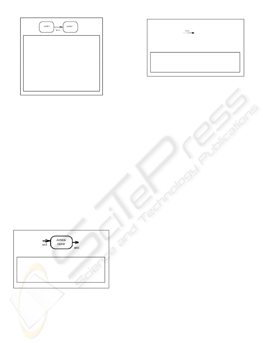
Rule 1. An activity diagram is translated into a B
model.
ActivityNode can be described by their type (ac-
tion node, initial node, decision node .) and an at-
tribute id to verify their uniqueness, consequently.
This abstract class can be seen as a description of
a set of objects identified by two attributes: id and
type. We suggested so to translate an abstract class
ActivityNode into an abstract set and all the derived
classes are transformed into data included in this ab-
stract set. The most appropriate B expression is the B
record (Abrial, 1996).
rec(ident1 : x, ident2 : y, , identn : t)
Where (x, y, ..t, E
1
, E
2
, , E
N
) are respectively the
values and type of fields (ident
1
, ident
2
, ident
n
). Since
the derived nodes are identified by their identifier and
their type, we propose to specify two fields for the
record: field Id
n
ode to identify the node and field and
Type to indicate its type. The abstract class is so trans-
lated into the following B record:
Nodes = Struct(Id − node : integer, Type : String).
In that manner, each node is considered as
data record of Nodes and then is translated into
rec(Id = a, Type = b).
Rule 2. The abstract class ActivityNode is trans-
lated into a B record: Nodes = Struct(Id − node :
integer, Type : String), in the clause DEFINITION of
the B model, and having as elements the different
nodes defined in the activity diagram that we aim to
translate. The nodes are then translated into vari-
ables node
i
, declared in the VARIABLES clause and
typed in the INVARIANT clause: node
i
∈ Nodes.
The abstract class ActivityEdge is related with
the class ActivityNode by two relations: target
and source. Hence, each edge has only one target
node and one source node. Besides to this relation,
the activity diagrams meta-model specifies other
relation with the class ValueSpeci f ication : guard, to
indicate that an edge is carrying tokens or not. We
propose so to specify four fields to describe those
relations:Id-edge, Id-source, Id-target and Ready to
indicate if the edge is carrying tokens or not.
Rule 3. The abstract class ActivityEdge is translated
into a B record: Edges = (Id
e
dge : integer, id
s
ource :
integer, Id
t
arget : integer, ready : boolean), declared
in the clause DEFINIT ION of the B model, and hav-
ing as elements the different edges defined in the ac-
tivity diagram that we aim to translate. The edges
are then translated into variables edge
i
, declared in
the VARIABLES clause and typed in the INVARIANTS
clause: arc
i
∈ Edges.
ICSOFT 2010 - 5th International Conference on Software and Data Technologies
330
SYSTEM
Mdl0
SYSTEM
M
o
d
e
l0
DEFINITIONS
Nodes
==
st
r
uct
(
i
d
n
ode:
I
N
TE
G
ER
,
T
ype:
I
N
TE
G
ER
);
Nodes
st uct
(
d
_
ode: N G , ype: N G
);
Edges==struct(Id_node:INTEGER,Id_source:INTEGER,
Id_target: INTEGER,ready:BOOL)
VARIABLES node1, node2, arc1
INVARIANTS
node1
∈
Nodes
∧
node2
∈
Nodes
∧
arc1∈Ed
g
es
g
INITIALIZATION
d1
d2
(1 AN)
(2 AN)|| 1
(112FALSE)
no
d
e
1
, no
d
e
2
:= rec
(1
,
AN)
, rec
(2
,
AN)||
arc
1
:=rec
(1
,
1
,
2
,
FALSE)
;
The semantics translation focuses on the meaning
of each concept. An action node is being executing
when all its incoming control and data tokens are
available. We suggest converting an action node into
an event B stating in its guard that all the incoming
edges are ready. Consequently, we propose an
universal predicate Q witch verifies for each edge
included in the record Edges if it has as target the
action node that we aim to translate and if its field
ready is evaluated to true.
Rule 4. An action node N is interpreted as event B
having as structure: SELECT guard THEN substi-
tutions END, its guard consist of the predicate Q =
∀x(x ∈ Edges ∧ x
0
Id
t
arget = N ⇒ x
0
ready = True)
while its substitution denotes the disabling of the
incoming edges and the enabling of the outgoing
ones.
EventAction=
SELECT∀x.(x
∈
Edges
∧
x’Id_target=id⇒ x’ready=True
)
THEN
arc1’ready:=False;arc2’ready:=True
END
END
Rule 5. The initial node is interpreted as an in-
struction, asserted in the clause INITIALISATION,
initializing its outgoing edges field ready at true.
Translation of Fork/Join Node. A fork node is used to
describe parallel behaviors, while Join node is used
to synchronize concurrent flows. It has to wait for the
enabling of all its incoming edges and then it disables
them and enables its outgoing one. A fork node
is converted into an event: SELECT guard THEN
substitutions END, which enables simultaneously the
outgoing flows once the incoming one is enabled.
EventFinal=
SELECT
(
∃
x(
x
∈
Edges
∧
x
’
Id C
= N
∧
x
’
ready
=True))
THEN
SELECT
(
∃
x
.
(
x
∈
Edges
∧
xId
_
C
=
N
∧
xready
=True))
THEN
a12’ready:=False…
END
Rule 6. A final node N is interpreted as an event B
having as structure: SELECT guard THEN substi-
tutions END, where the guard consists of the predi-
cate Q = ∃x(x ∈ Edges ∧ x
0
Id
t
arget = N ∧ x
0
ready =
True), while its substitutions denote the disabling of
all the edges.
2.2 Step2: Proof Generation
Giving an UML Activity Diagram, we aim through
translating it into B specification at verifying required
properties which are mainly: deadlock freeness, live-
lock freeness and reachability. An event B model
deadlocks when there is no held guard. Thus, we
have to verify that there is always at least a valid
guard. For example, consider G
1
, G
2
, ..., G
n
which de-
note the guards of all the events, the coherence con-
straint, denoted CC, can be formulated by the con-
dition: CC = G
1
∨ G
2
∨ ... ∨ G
n
. To prove that this
constraint always holds, we have to prove its satisfac-
tion after each hidden event. We have so to assert it
in the INVARIANT clause since it is checked for any
hidden event. The activity diagram is then coherent if
the initialization satisfies the Invariants and if an event
holds, it preserves also Invariants. Having identified
the B specification of the UML AD of ??, we will now
focus on proving the coherence constraint, asserted in
the INVARIANT clause. We start by identifying the
Guard of each event:
Guardo f EventAction = ∀x(x ∈
Edges ∧ x
0
Id
t
arget = 2 ⇒ x
0
ready = True) ≡
arc1
0
ready = True ∧ arc4
0
ready = True
Guardo f EventAction = ∀x(x ∈ Edges∧ x
0
Id
t
arget =
2 ⇒ x
0
ready = True) ≡ arc2
0
ready = True
Guardo f EventOb ject = ∃x(x ∈ Edges∧x
0
Id
t
arget =
4 ⇒ x
0
ready = True) ≡ arc3
0
ready = True
Guardo f EventFinal = ∃x(x ∈ Edges ∧ x
0
Id
t
arget =
5 ⇒ x
0
ready = True) ≡ arc5
0
ready = True.
AN UML ACTIVITIES DIAGRAMS TRANSLATION INTO EVENT B SUPPORTING THE SPECIFICATION AND
THE VERIFICATION OF WORKFLOW APPLICATION MODELS - From UML Activities Diagrams to Event B
331

3 CONCLUSIONS
The main contribution of this work is related to The
translation of UML activity diagrams into the event
B abstract system formalism. The translation covers
syntactical a semantic views of UML AD. We have
focused both on the UML activity model and its met-
model in order to avoid lack of information while
translating. The current work fills a gap between the
widely practiced UML AD for workflow modelling
and the emerging proof based on abstract machines,
refinement and theorem proving. In the proposed ap-
proach, a workflow application is initially modelled
graphically with UML activity diagrams. After that,
the resulting graphical model is translated into Event
B model. Required properties for UML AD are then
added as invariants in the resulting model. These
properties are verified by the use of an event B tool.
Hence UML AD could be verified. We have so pro-
posed a set of generic rules describing UML activity
diagram in event B. The derived static part of the re-
sulting event B model capture the syntax of UML AD
and events capture the semantics of UML AD evolu-
tion.
REFERENCES
Abrial, J.-R. (1996). Abrial, j-r. (1996) extending b without
changing it (for developing distributed systems). In
Habrias, editor, First B Conference, Putting Into Prat-
ice Methods and Tools for Information System Design,
Nantes, France.
Bjorner, D. (1987). Vdm a formal method at work. In Proc.
of VDM Europe Symposium. Springer-Verlag. LNCS,
editor.
Conallen, J. (1999). Modeling web application architec-
tures with uml. In Communications of the ACM, 42
(10).
Holz, E. (1997). Application of uml within the scope of
new telecommunication architectures. In In GROOM
Workshop on UML, Mannheim. Physical Verlag.
Jacobson, J. and Booch, G. (1998). The unified modeling
language reference manual. In Addison- Wesley.
OMG (2003). Unified modeling language superstructure.
http://www.omg.org/
technology/documents/formal/uml.htm.
Pllana, S. and Fahring, T. (2002). Modeling parallel aplica-
tions with uml. In In 15th International conferences
on parallel and distributed computing systems, USA-
ISCA.
Vidal, J. S. (2006). Matrise de la cohrence des modles uml
d’applications, approche par l’analyse des risques lis
au langage uml. In thse de doctorat, Institut National
des Sciences Appliques de Toulouse, France.
ICSOFT 2010 - 5th International Conference on Software and Data Technologies
332
