
USER CONTEXT MODELS
A Framework to Ease Software Formal Verifications
Amine Raji and Phillipe Dhaussy
LISyC-ENSIETA, 2 rue Franc¸ois Verny 29806, Brest Cedex 9, France
Universit
´
e Europ
´
eenne de Bretagne, Brest, France
Keywords:
Formal verifications, Context description language, Model transformation, User context models, Property
specification patterns.
Abstract:
Several works emphasize the difficulties of software verification applied to embedded systems. In past years,
formal verification techniques and tools were widely developed and used by the research community. However,
the use of formal verification at industrial scale remains difficult, expensive and requires lot of time. This is
due to the size and the complexity of manipulated models, but also, to the important gap between requirement
models manipulated by different stackholders and formal models required by existing verification tools. In
this paper, we fill this gap by providing the UCM framework to automatically generate formal models used
by formal verification tools. At this stage of our work, we generate behavior models of environment actors
interacting with the system directly from an extended form of use cases. These behavioral models can be
composed directly with the system automata to be verified using existing model checking tools.
1 INTRODUCTION
Verification of software systems is an important task
that aims to check whether design meets intended re-
quirements. Formal methods have demonstrated their
potential in this area especially through the so called
model checking. However, the application of such
techniques in industrial practices is still limited w.r.t
the growing need of quality and reliability of devel-
oped software.
In this paper we present our approach to overcome
this shortcoming by presenting a model based ap-
proach to bridge the gap between high level require-
ment models and models required by existing formal
verification tools. The proposed approach aims to
smooth the way properties and contexts
1
are derived
from requirement documents and specifications.
We previously presented CDL (Context descrip-
tion language)(Dhaussy et al., 2008) to fill the gap
between user models
2
and formal models required to
perform formal verifications. CDL is presented in the
form of UML like graphical diagrams (subset of ac-
tivity and sequence diagrams) to capture environment
1
By contexts we refer to interactions that happen be-
tween the system under study and its environment.
2
Models manipulated during development phases of the
development process.
interaction. Additionally, a textual syntax is prosed to
formalize properties to be check using property de-
scription patterns (Dwyer et al., 1999). CDL was
evaluated through several aeronautic and military in-
dustrial case studies (Dhaussy et al., 2009). Con-
clusions of this evaluation is that CDL considerably
helps practitioners to formally verify whether de-
signed models meet intended requirements.
However, CDL is a low level language that re-
quires design details since early development phases
to produce precise enough specifications for formal
verifications. We are currently working on an inter-
mediate concept called UCM (User Context Models).
UCM is thought to be user oriented and aims to uti-
lize models constructed during development phases to
automatically generate formal models (i.e CDL mod-
els). The idea is to encourage users to put more details
and avoid ambiguities during their modeling activities
to automatically derive formal specifications.
This paper is organized as follow: Section 2
presents a background on CDL models and context
aware verification techniques. Section 3 details the
UCM framework and argues how they can be useful
to fill the gap between requirement specification and
formal verification activities. Section 4 presents re-
lated works and Section 5 discusses future work and
draws some conclusions.
380
Raji A. and Dhaussy P. (2010).
USER CONTEXT MODELS - A Framework to Ease Software Formal Verifications.
In Proceedings of the 12th International Conference on Enterprise Information Systems - Information Systems Analysis and Specification, pages
380-383
DOI: 10.5220/0003019803800383
Copyright
c
SciTePress
2 BACKGROUND
In software verification, model checking is increas-
ingly used to verify that a formally specified model
satisfy some desired property (Lamsweerde, 2009).
In the most frequent form of model checking, the in-
puts to the checker are a formal state machine model
and a desired property formalized in temporal logic.
Applying this technique in an industrial context suf-
fer from the combinatorial explosion induced by the
internal complexity of the software to be verified.
One way to circumvent this problem consists of
specifying/restricting the context in which the system
will be used. This context corresponds to well-defined
operational phases, such as, for example, initializa-
tion, reconfiguration, degraded mode, etc. The sys-
tem is then tightly synchronized with its environment
so that properties can be checked in specific contexts
which limits the size of the generated state space.
In this context, CDL aims to ease the construction
of context models and to specify properties. CDL de-
scribes a system environment using activity and se-
quence diagrams, together with a textual syntax. Ac-
tivity and sequence diagrams are used to describe con-
texts, and the textual syntax to describe properties to
be checked. The properties are specified using prop-
erty description patterns and attached to specific ele-
ments in the activity diagram describing the context.
CDL have demonstrated its usefulness in porting
formal verifications into industrial practices through
several industrial projects (Dhaussy et al., 2009).
However, CDL models construction remains a man-
ual process requiring time and efforts to understand
the system specifications in order to produce precise
contexts’ interactions.
3 USER CONTEXT MODELS
The main idea is to encourage engineers to put enough
details in their daily constructed models. This en-
couragement is made through the UCM framework
that presents guidelines for constructing contexts and
specifying properties as well as algorithms to auto-
mate formal models generations from these models.
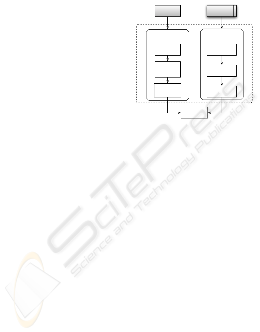
Figure 1 shows an overview of UCM content. The
left side of figure 1 presents different steps leading to
the generation of formal models describing the behav-
ior of different actors of the environment, i.e. context.
The right side shows the property specification activ-
ities that aims to formalize properties to be checked.
We have defined and formalized the generation
of behavioral models of the context using a model
based approach (the left side of figure 1). We use
UCM
Capture and formalization
of system contexts
Property specificaiton
Requirement
Documents
User
Models
Requirement
decomposition
Pattern
identification
Property
formalisation
Extended
use cases
Activity
diagram per
UC
Activity
diagram per
Actor
CDL
Figure 1: UCM content overview.
an extended form of use cases to capture system re-
quirements as well as possible exceptions and corre-
sponding handlers if any. The idea behind this step
is to gather all useful information about the system
behavior and its interactions with environment actors.
Constructed use cases are then used as input in our
model transformation to generate formal models di-
rectly processable by a model checker.
Extended use cases are similar to traditional use
cases except that they capture system requirements as
well as possible exceptions and corresponding han-
dlers if any (Mustafiz et al., 2009).In fact, many ex-
ceptional situations might appear during the execu-
tion of an application. The difficulties arising during
verification process are usually related to the missing
of relevant information about system behavior, espe-
cially when an exception endangers the normal execu-
tion of a use case. To encounter this problem, we pro-
pose that engineers (whom designed the system in the
first place) specify their systems using extended use
cases to foresee these exceptional situations and doc-
ument how the system should deal with them. This
approach leads engineers to systematically investigate
all possible exceptions arising in the environment that
the system may be exposed to.
We have proposed a metamodel of the extended
use cases (figure 2) and an algorithm to derive the be-
havior of different actors involved in the use case.
In figure 2, classes with a white background are
imported from the UML metamodel, and should be
related to the identical ones presented in (OMG,
2007). The classes with the filled background was in-
troduced to deal with exceptions and handlers in tra-
ditional use cases. The important point in the pro-
USER CONTEXT MODELS - A Framework to Ease Software Formal Verifications
381
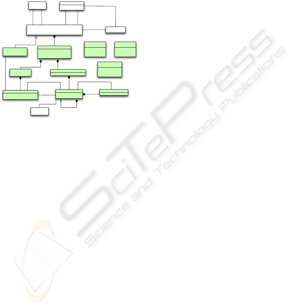
posed metamodel is that main scenario steps have to
be described in a structured natural language to be
transformed into actions in the generated activity di-
agram. Used structured language is RDL (Require-
ment Description Language) introduced in (Nebut
et al., 2003).
+outcome : Outcomekind
MainScenario
*
UseCase
Include
ExtentionPoint
+name : String
+description: String
Step
+step
*
+subSteps
+operator: Operator
Transition
+outgoing
0..1
1
+next
0..1
+incoming
Handler
success
degraded
failure
<<enumeration>>
OutcomeKind
*
user-goal
summary
subfunction
<<enumeration>>
LevelType
Extensions
+name : String
+Intention : String
+level : levelType
UseCaseBody
+name : String
+outcome : Outcomekind
Exception
1..*
+relatedStep
0..*
+exception
0..1
+next
0..*
+handler
1
+exception
1
+addition
1
+base
+include*
condition:
BooleanExpression
Extend
+extend
+extension
*
1
1
+base
*
+extensionPoint
+extensionPoint
{Ordered}
*
1..*
1
Actor
1 +performedBy
fork
join
choice
<<enumeration>>
Operator
0..* +extesions
1 +mainScenario
1 +body
{Ordered}
{Ordered}
Figure 2: Metamodel of extended use case integrated in the
metamodel of UML.
After use case modeling, our algorithm consists in
transforming each use case to a UML activity diagram
(T 1) and then extract the behavior of the each actor in
a separate activity diagram (T 2).
The approach used for (T 1) is partially inspired
form the work presented in (Guti
´
errez et al., 2008).
Authors in the cited article propose a method for rep-
resenting functional requirements by automatically
transforming use cases to activity diagrams. However,
proposed use cases don’t support the handling of iden-
tified exceptions. We propose a model transformation
of extended use cases with handler to UML2 activity
diagrams. The process of transforming extended use
cases to activity diagrams consists in applying trans-
formation rules enumerated bellow:
1. generate an activity for each use case,
2. generate an activity partition for each identified
actor in the use case plus an additional one for the
system,
3. generate an action for each Step in the main sce-
nario,
4. add generated action to the activity partition of
the actor identified in the performedBy attribute,
5. generate a decision node for each exception and
additional activity for each handler,
6. generate an activity final node for each outcome
in the use case labelled with a stereotype corre-
sponding to the output kind,
7. link all generated elements using control flow.
To derive the behavior of each environment actor
(T 2), we propose an algorithm that derive these be-
havior while preserving the consistency of the global
activity diagram. The algorithm extracts nodes and
edges related to the same actor (based on activity Par-
titions) then links them together using control flow.
To preserve the semantics of the global behavior de-
scribed in the source activity diagram, events trigger-
ing the flow between actions and coming from the
system or other actors are added to the targeted ac-
tivity diagram. These events are represented with in-
stances of the AcceptEventAction class (OMG, 2007).
Thus, the flow between actions in the activity of a
specific actor is conditioned with the reception of the
corresponding event. Thus, the master rule to trans-
form each activity group into a single activity diagram
(AD) is defined as follows.
mapActivityGroup2ActivityDiagram()
ADi = createInitialNode()
processOwnedElements(ADi)
createActivityFinalNode(ADi)
The result of applying our synthesis algorithm on
the activity diagram generated from (T 1) produce an
activity diagram for each actor participating in the
considered use case. To preserve interactions between
actors, instances of the AcceptEventAction class are
added, each time a transition linking two activities re-
lated to two different actors is detected.
4 RELATED WORKS
The work presented in (Almendros-Jimenez and Irib-
arne, 2004) describes an approach to translate use
case-based functional requirements to activity charts.
The source models are use cases diagrams with sup-
port of inclusion and generalization relationships.
In (Guti
´
errez et al., 2008), authors propose a model
based approach to generate an activity diagram mod-
eling the use case scenario. A functional requirement
metamodel was proposed to represent the use case
scenario with possible exceptions.
Mustafiz et. al (Mustafiz et al., 2009) propose
an algorithm that transforms dependability-focused
use cases with handlers into activity diagrams. The
transformation takes textual use cases description as
source to produce activity diagram model respecting
the use case hierarchy source model. Our approach
ICEIS 2010 - 12th International Conference on Enterprise Information Systems
382

differs in the sense that we begin with informal re-
quirements specification, namely extended use cases,
apply a model-driven process to map requirements to
activity diagrams, and then, automatically extract for-
mal behavioral models of actors that interact with the
system using our synthesis algorithm.
5 CONCLUSIONS AND FUTURE
WORK
In this paper we introduce the UCM framework to
ease the integration of formal verification techniques
into software development. We have proposed a
metamodel of extended use cases with handlers that
address detected exceptions. Exceptional situations
are less common and hence the behavior of the system
in such situations is less obvious. Therefore, the pro-
posed metamodel represents a good starting point for
the identification of environment actors that might in-
teract with the system. We have also proposed an ap-
proach to automatically synthesis environment enti-
ties behavior directly from constructed use cases. We
have generated an activity diagram that describe the
behavior of each use case using our model transfor-
mation rules. Then, we extract the behavior of each
actor participating to the activity in a separate activ-
ity diagram. The motivation behind this contribution
is to ease the use of formal verification techniques by
providing early context descriptions with enough pre-
cision to feed formal verification tools. To the best of
our knowledge, there is no similar work dealing with
this particular problem.
As a future work, we firstly plan to formalize re-
quirement decomposition and formalization (the right
side of Figure 1). Secondly, we would like to eval-
uate the usefulness of introducing UCM into indus-
trial practices as we did for CDL in (Dhaussy et al.,
2009). And finally, we will integrate our approach in
the complete verification process.
REFERENCES
Almendros-Jimenez, J. and Iribarne, L. (2004). Describing
use cases with activity charts. Metainformatics, 3511
of LNCS. Springer:141–159.
Dhaussy, P., Auvray, J., De belloy, S., Boniol, F., and Lan-
del, E. (2008). Using context descriptions and prop-
erty definition patterns for software formal verifica-
tion. In Workshop Modevva08,hosted by ICST 2008.
Dhaussy, P., Pillain, P.-Y., Creff, S., Raji, A., Traon, Y. L.,
and Baudry, B. (2009). Evaluating context descrip-
tions and property definition patterns for software for-
mal validation. MoDELS, LNCS 5795:438–452.
Dwyer, M. B., Avrunin, G. S., and Corbett, J. C. (1999).
Patterns in property specifications for finite-state veri-
fication. ICSE, pages 411–420.
Guti
´
errez, J., Nebut, C., Escalona, M., and Mej
´
ıas, M.
(2008). Visualization of use cases through automat-
ically generated activity diagrams. MODELS.
Lamsweerde, A. V. (2009). Requirements engineering:
From system goals to uml models to software speci-
fications. Book.
Mustafiz, S., Kienzle, J., and Vangheluwe, H. (2009).
Model transformation of dependability-focused re-
quirements models. Proceedings of the 2009 ICSE
Workshop on Modeling in Software Engineering.
Nebut, C., Fleurey, F., LeTraon, Y., and J
´
ez
´
equel, J.-M.
(2003). A requirement-based approach to test prod-
uct families. 5th Intl. Workshop on Product Family
Engineering (PFE-5).
OMG (2007). UML 2.1.2 Superstructure.
USER CONTEXT MODELS - A Framework to Ease Software Formal Verifications
383
