
Compositional Verification of Business Processes by
Model–Checking
Luis E. Mendoza
1
, Manuel I. Capel
2
and Mar´ıa P´erez
1
1
Processes and Systems Department, Sim´on Bol´ıvar University
P.O. box 89000, Baruta, Caracas 1080-A, Venezuela
2
Software Engineering Department, University of Granada
ETSI Informatics and Telecommunication, 18071 Granada, Spain
Abstract. The work presented in this article is aimed at a contribution to the En-
terprise Information Systems (EIS) verification. We describe here a Formal Com-
positional Verification Approach (FCVA)—based on Model–Checking (MC) tech-
niques— applied to the verification of Business Process (BP) models represented
by Business Process Modelling Notation (BPMN) diagrams. FCVA is composi-
tional and thus allows the verification of a complex BP model carried out from
verification of its parts. FCVA and a proposal of temporal semantics for BPMN
allows the expression of time–dependent constructs of BP Task Models (BPTM)
supported by an EIS. The interpretation of the BPMN graphical modelling enti-
ties into a formal specification language (CSP+T) allows us to use state–of–the–
art MC tools to verify the behavioural part of BP models. A real–life example in
the field of the Customer Relationship Management (CRM) business is presented
to demonstrate the FCVA application in a practical way.
1 Introduction
Enterprise Information Systems (EIS) manage enterprise business, apply strategic and
economic decisions, and hold communication with business partners. In this sense, the
EIS implements cross–functional Business Processes (BPs), i.e., the set of ways in
which management chooses to coordinate the work to achieve their (business) objec-
tives and user goals, which transcends the boundaries between sales, marketing, man-
ufacturing, and research and development. Therefore, an organization must have been
obtained previously, as result of the Business Process Modelling (BPM), the complete
definition of the set of BPs that support the EIS. Due to BPs specific characteristics
(people integration, business rules, business goals, events, information, and resources)
[1], the validation of BP Task Model (BPTM) is an extremely expensive and risky ac-
tivity if it is delayed until the EIS deployment phase.
The main goal of Business Process Modelling Notation (BPMN) [1] being to pro-
vide a readily understandable notation for all its users, the lack of a precise semantics
of its modelling entities impedes rigourous analysis and reasoning about the models
obtained [2]. To cope with the above described situation, we propose an instantiation
of our compositional verification framework, called Formal Compositional Verification
E. Mendoza L., I. Capel M. and PÃl’rez M.
Compositional Verification of Business Processes by Modelâ
˘
A ¸SChecking.
DOI: 10.5220/0003022300600069
In Proceedings of the 8th International Workshop on Modelling, Simulation, Verification and Validation of Enterprise Information Systems (ICEIS 2010), page
ISBN: 978-989-8425-12-6
Copyright
c
2010 by SCITEPRESS – Science and Technology Publications, Lda. All rights reserved

Approach (FCVA) [3], which uses MC techniques and makes it possible to verify a
BPTM supported by an EIS using the formal semantics of Communicating Sequential
Processes (CSP) –based process calculus. We complement our FVCA [3] with a timed
semantics of BPMN defined in terms of the Communicating Sequential Processes +
Time (CSP+T) [4] formal specification language, which extends BPMN modelling en-
tities with timing constraints in order to allow the expression of BPTM time–dependent
constructs. By a sound interpretation of FCVA elements into Kripke Structures (KS)
[5], it then becomes feasible to verify the behaviour of global BP (i.e., the BPTM) from
its local BPs’ participants.
Different works address the verification and validation of BP modelled with BPMN.
In [6] is presented a extended survey of recently proposed verification techniques for
verifying BPMN models and a comparison between them and with respect to motiva-
tions, methods, and logics. Differently from other research, our work is aimed at giving
a systemic, integrated vision of specification, design and verification of BPTM derived
from BPs, by incorporating the use of MC tools in the specification and verification of
BPTM into the EIS development cycle.
The remainder of this paper is organised as follows. In section 2 short introduc-
tions to time semantics for BPMN modelling entities and to the Clocked Computation
Tree Logic (CCTL) specification language are provided. In section 3 FCVA for BPMN
verification is presented, followed by a formal description and validation of the com-
positional verification proposal. Section 4 describes the application to a BPM example
related to the CRM business. Finally, in Section 5, conclusions are given and future
work is described.
2 BPTM’s Behaviours in a Common Semantic Domain
Most temporal logics and other system description formalisms, used for reactive sys-
tems (as BPTM) specification, can be interpreted as KS. According to [5] the systems
best suited to verification by MC are those that are easily modelled by (finite) automata,
such as KS ones [5]. Accordingly, [7] states that translating formulae in temporal log-
ics to automata is a standard approach for implementing MC. Therefore, in this paper
we use Timed B
¨
uchi Automaton (TBA) because these are the simplest automata over
infinite words [5] able to represent time regular processes [8].
2.1 BPTM Model
To obtain a complete description of the BPTM’s behaviour interpreted into CSP+T
process terms, we apply the transformation rules that we briefly introduce below, which
assume the semantics of the BPMN analysis entities given in [2] as the starting point
for their definition. As a result of a mapping from BPMN [1] to CSP+T processes, each
BPMN modelling entity (flow objects, connecting objects, and swimlanes) yield a syn-
tactical sequential process term and specifies how to represent the entire participant’s
behaviour, according to discrete timed events and sequences of events. Due to space
limitations, Table 1 only shows a graphical example of some transformation rules used
for obtaining CSP+T process terms from BPMN modelling entities. The complete rules
61
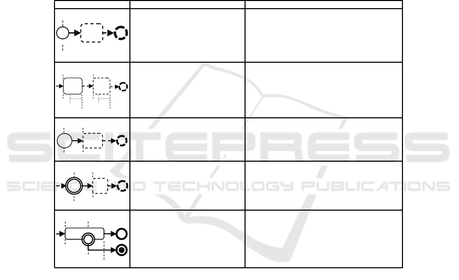
set is presented in [9]. We denote as ǫ
x
the invocation events of the BPMN modelling
entities, Sx.ran.min and Sx.ran.max as the minimum and maximum time span of
Sx activities, respectively, and stime.ran and itime.ran as the time delay defined by
timer start and timer intermediate events, respectively, according to BPMN [1]. Briefly
explained, the transformation is performed by mapping: (1) every BPMN modelling
entity to a prefixed CSP+T process term; (2) every discrete duration time to a CSP+T
event–enabling interval; and (3) the external choice to alternative selections performed
by the environment of each process is applied to ensure that all processes terminate at
the end of the business process execution.
Table 1. Some mapping rules from BPMN modelling entities to CSP+T terms.
BPMN element Description CSP+T process
S1
«
v
«
start
end
The start event corresponds to the
CSP+T ⋆ instantiation event and the v
⋆
marker variable is used to save the oc-
currence time of event ⋆.
P (start) =(⋆ ⋊⋉ v
⋆
→ SKIP # P (start))
(ǫ
end
→ SKIP )
S1 S2
S1.ran.max
S1.ran.min
S2.ran.max
S2.ran.min
ε
S1
ε
S2
v
S1
v
S2
end
The S2 activity begins when the ǫ
S1
event occurs and the invocation of
S2 activity (i.e., the occurrence of
ǫ
S2
event) must occur within the
[S1.ran.min, S1.ran.max] time
interval. The activity S1 come before
activity S2.
P (S1) =(ǫ
S1
⋊⋉ v
S1
→ SKIP #
I(S1.ran.max − S1.ran.min,
v
S1
+ S1.ran.min).ǫ
S2
→ SKIP # P (S1))
(ǫ
end
→ SKIP )
S1
¹
ε
S1
stime.ran
end
«
v
stime
The timer start event establishes that the
S1 activity must begin (i.e., the occur-
rence of ǫ
S1
event), stime.ran time
units after the occurrence of ⋆ instanti-
ation event.
P (stime) = ( ⋆ ⋊⋉ v
stime
→ SKIP #
I(stime.ran, v
stime
) → SKIP #
ǫ
S1
→ SKIP # P (stime))
(ǫ
end
→ SKIP )
S2
¹
ε
itime
ε
S2
v
itime
end
itime.ran
According to the timer intermediate
event, the S2 activity must begin
(i.e., the occurrence of ǫ
S2
event),
itime.ran time units after the occur-
rence of ǫ
itime
event.
P (itime) =(ǫ
itime
⋊⋉ v
itime
→ SKIP #
I(T
itime
, v
itime
) → SKIP #
ǫ
S2
→ SKIP # P (itime))
(ǫ
end
→ SKIP )
S1
¹
ε
S1
S1.ran.max
ε
exc
v
S1
end
abort
etime.ran
The S1 activity execution can be in-
terrupted (i.e., the occurrence of ǫ
exc
event) at any time since its inception
(i.e., the occurrence of ǫ
S1
event) and
until its total duration ends (i.e., within
the [v
S1
, S1.ran.max] time inter-
val).
P (S1) =(ǫ
S1
⋊⋉ v
S1
→ SKIP #
I(S1.ran.max − S1.ran.min,
v
S1
+ S1.ran.min).ǫ
end
→ (SKIP
a
I(S1.ran.max,
v
S1
).ǫ
exc
→ SKIP #
abort.1 → ST OP ) # P (S1))
(ǫ
end
→ SKIP )
2.2 BPTM Properties
To specify the properties that the BPTM must exhibit, we use the CCTL [10], which is
an interval temporal logic that allow us to carry out a logical reasoning at the level of
time intervals, instead of instants. See [10] for more details. The algorithm described in
[8] is used to construct a discrete TBA semantically equivalent to a CCTL formula φ.
Afterwards, using the procedure described in [11], the TBAs of the BPTM properties
described previously are transformed into CSP+T process terms. Thus, the expected
behaviour of a BPTM is interpreted into a CSP+T process term P . Thus, the assertion
P φ denotes that P meets the specification φ, where represents that P simulates
62

φ (the simulation assertion), meaning that any behaviour of φ can be matched by a cor-
responding behaviour of P (but not necessarily vice versa). Consequently, by applying
the rules in Table 1 and the simulation operator, we can reason and express the BPTM
properties in the same specification language as the BPTM model.
3 Compositional Verification Approach
Our approach is based on the fact that the system C has been structured into several
verified components working in parallel, C =
f
i:1..n
C
i
, where each component C
i
satisfies the property φ
i
, which represents the specification of the expected behaviour
for the component. Our main goal here is to make possible the verification of the entire
system’s behaviour from its verified components. In this sense,
Definition 1 (Property compositionality). A property φ is compositional iff for any two TBA
A
1
, A
′
1
, and A
2
with L(A
2
) ∩ L(φ) = ∅ holds
(A
1
φ) ⇒ ((A
1
kA
2
φ) ∨ A
1
kA
2
δ)) and (1)
((A
1
⊑ A
′
1
) ∧ (A
′
1
φ)) ⇒ (A
1
φ) (2)
Local properties are preserved by parallel composition when the labelling is dis-
joint:
Lemma 1. For two TBAs A
1
and A
2
and properties φ
1
and φ
2
with Σ
1
∩Ω
2
= ∅, Σ
2
∩Ω
1
= ∅,
L(A
1
) ∩ L(A
2
) = ∅ holds:
((A
1
φ
1
) ∧ (A
2
φ
2
)) ⇒ (A
1
kA
2
φ
1
∧ φ
2
). (3)
On the other hand, it is also a requirement that composition preserves refinement in
the case of parallel composition:
Lemma 2. For two composable TBAs A
1
and A
2
, and any automata A
′
2
holds
A
2
⊑ A
′
2
⇒ (A
1
kA
2
⊑ A
1
kA
′
2
). (4)
Each component must also satisfy the “invariant” (ψ
i
) expression which represents
the behaviour of other system components with respect to C
i
. The special symbol ¬δ
is used to denote that deadlock (i.e., a state without any outgoing transition) cannot be
reached. The property φ and invariant ψ that are satisfied by the system C, have been
obtained from the local properties φ
i
(i.e.,
V
i:1..n
φ
i
⇒ φ) and invariances ψ
i
(i.e.,
V
i:1..n
ψ
i
⇒ ψ), respectively. As result, we can obtain the complete verification of the
system by using the Theorem 1:
Theorem 1 (System Compositional Verification). Let the system C be structured into sev-
eral components working in parallel, C =
f
i:1..n
C
i
. For a set of T BA(C
i
) describing the
behaviour of components C
i
, properties φ
i
, invariants ψ
i
, and deadlock δ, with
T
i:1..n
Σ
i
= ∅,
T
i:1..n
Ω
i
= ∅, and
T
i:1..n
L(T BA(C
i
)) = ∅, the following condition holds:
T BA(C) (φ ∧ ψ ∧ ¬δ) ⇔
n
i:1..n
T BA(C
i
)
^
i:1..n
(φ
i
∧ ψ
i
) ∧ ¬δ, (5)
where T BA(C) = k
i:1..n
T BA(C
i
).
63
The practical application of assertion (5) includes (manually) performing an induc-
tive satisfaction checking process on the range of the components number (i : 1..n) of
the system. The FDR2 [12] model checker can automate this proof.
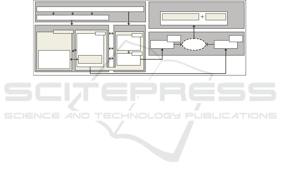
Based on previous concepts and ideas, we propose a possible instantiation of our
conceptual scheme called FCVA [3], as shown in Fig. 1, to specify and verify BPTM
derived from BPs supported by EIS. The rationale of FCVA instantiation is that the
behavioural correctness of local BPs can be individually verified, in isolation, based
on the well–defined communication behaviour specified by their message flows, and
verification of the global BP behaviour performed using the results of the verification
of local BPs. Our instantiation uses the CSP+T process calculus, which has a simple but
powerful form of composition given by concurrent composition and hiding operators.
VERIFICATION OF LOCAL BPs
BPTM MODELLING BPTM BEHAVIOUR
SPECIFICATION
BUSINESS PROCESS MODELLING GLOBAL BP CORRECTNESS CAN BE ANALYSED BY BUSINESS
ANALYSTS AND DESIGNERS
BPMN MODELLING
ENTITIES SPECIFICATION
ACCORDING TO CSP+T
SEMANTICS
FLOW OBJECTS
–
CONNECTING OBJECTS
–
SWIMLANES
BPMN CSP+T
INFORMATION - EVENTS - RESOURCES - GOALS - ACTIVITIES - BUSINESS RULES
SET OF BPMN BUSINESS PROCESS DIAGRAMS
BPTM ABSTRACT BEHAVIOUR BPTM MODEL
COMPOSITIONAL VERIFICATION OF GLOBAL BP
COMPOSITION OPERATOR
OF PROCESS ALGEBRA
DEDUCTIVE
TECHNIQUES
BPTM BEHAVIOUR
OBTAINED AS A
PARALLEL
COMPOSITION OF
CSP+T
PROCESSES
SET OF CSP+T
PROCESS TERMS
CSP+T
TIMING AND
ORDERING
SPECIFICATION
BUSINESS RULES
AND GOALS,
AND TEMPORAL
CONSTRAINTS
CCTL
CSP+T
Kripke structures semantics
EXPECTED
BEHAVIOUR
PERFORMED
BEHAVIOUR
MODEL
CHECKING
TRACES –
FAILURES
TRACES –
FAILURES
Fig.1. Integrated view of compositional verification for BPTM.
The BPM is considered outside the scope of FCVA. Both the formal description
of the BPTM behaviour and the specification of its properties must be directed by the
BPMN Business Process Diagram (BPD) and the business rules and goals, respectively.
FCVA instantiation consists of the following integrated processes (see Fig. 1):
BPTM Modelling. Firstly, the complete description of the BPTM’s behaviour, mod-
elled by the CSP+T process term T (C) is interpreted into a set of CSP+T process
terms T (C
i
) by using the proposed time semantics for BPMN modelling entities
introduced in section 2.1.
BPTM Behaviour Specification. Then, requirementsand temporal constraints that the
BPTM must fulfill are specified in CCTL, which is based on the interval structure
and time–annotated automata [10]. Afterwards, these properties are expressed by
CSP+T process terms T (φ
i
), T (ψ
i
), T (¬δ).
Verification. Finally, by performingthe followingsteps, we proceedto verifythe BPTM
behaviour:
1. Firstly, the local process T (C
i
) representing the local BPs are model checked
against the set of process terms T (φ
i
), and T (ψ
i
), T (¬δ). According to the
trace and failure semantics of CSP–based algebra, we proceed to verify:
T (φ
i
) ⊑
T
T (C
i
) ∧ T (ψ
i
) ⊑
T
T (C
i
) ∧ T (¬δ) ⊑
T
T (C
i
)
T (φ
i
) ⊑
F
T (C
i
) ∧ T (ψ
i
) ⊑
F
T (C
i
) ∧ T (¬δ) ⊑
F
T (C
i
)
2. Secondly, we obtain the verification of local BPs correctness, according to the
following assertions:
64
– Related to consideration of safety issues:
∀t ∈ traces(T (φ
i
))∃t
′
∈ traces(T (C
i
)) : t
′
⇒ φ
i
⇔ T ( C
i
) |= φ
i
∀t ∈ traces(T (ψ
i
))∃t
′
∈ traces(T (C
i
)) : t
′
⇒ ψ
i
⇔ T ( C
i
) |= ψ
i
∀t ∈ traces(T (¬δ))∃t
′
∈ traces(T (C
i
)) : t
′
⇒ ¬δ ⇔ T (C
i
) |= ¬δ
– Related to consideration of liveness issues:
∀(t, X) ∈ SFJT (φ
i
)K∃(t
′
, X) ∈ SF JT (C
i
)K : (t
′
, X) ⇒ φ
i
⇔ T (C
i
) |= φ
i
∀(t, X) ∈ SFJT (ψ
i
)K∃(t
′
, X) ∈ SF JT (C
i
)K : (t
′
, X) ⇒ ψ
i
⇔ T (C
i
) |= ψ
i
∀(t, X) ∈ SFJT (¬δ)K∃(t
′
, X) ∈ SF JT (C
i
)K : (t
′
, X) ⇒ ¬δ ⇔ T (C
i
) |= ¬δ
3. Finally, by the application of Theorem 1 we obtain the complete verification
of the BPTM behaviour T (C), according to the assertion (5) instantiated for
CSP+T process terms (T (C) = k
i:1..n
T (C
i
)).
4 Example of Application
To show the applicability of our proposal, it was applied to a BPM enterprise–project
related to the CRM business. We will only show an example of application of the timed
semantics proposed for BPMN and we only focus on the verification of one CRM BP.
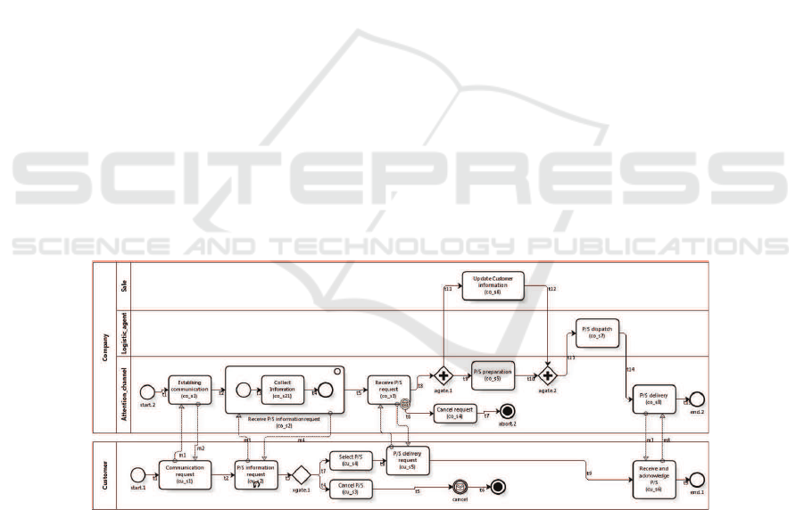
We selected to work with the Product/Service Sell BP, due to its importance to the
CRM strategy. The required information to allow carrying out formal reasoning about
the CRM participant collaboration is displayed in the Product/Service Sell BPD shown
in Fig. 2, which allows a Company to perform the activities associated with selling a
Product/Service requested by a Customer. As shown in Fig. 2, the BP depicts a high
collaboration between the participants to achieve their execution, which means a syn-
chronization of the activities involved in message flows.
Fig.2. BPD of the Product/service Sell BP.
65

4.1 BPTM Definition and Description
To obtain the specification of the Product/Service Sell BPD in CSP+T, according to the
proposal briefly described in section 2.1, we define the sets CU and CO, for indexing
the processes mapped to the modelling entities of Customer (i.e., Cus) and Company
(i.e., Com) participants, respectively (see Fig. 2):
CU ={start.1, cu s1, cu s2, cu s3, cu s4, cu s5, cu s6, xgate.1, end.1, abort.1}
CO ={start.2, co s1, co s2, co s21, co s3, co s4, co s5, co s6, co s7, co s8, agate.1, agate.2,
end.2, abort.2}
Cus =let X =i : (αY \{f in.1, abt.1}) • (i → Xf in.1 → SKIP abt.1 → ST OP )
Y = ( ki : CU • αP (i) ◦ P (i))
within(Y |[αY ]|X)\{| init.Cus |}
Com = let Z =j : (αR\{f in.2, abt.2}) • (j → Zfin.2 → SKIP abt.2 → ST OP )
R =(kj : CO • αP (j) ◦ P (j))
within(R|[αR]|Z)\{| init.Com |}
where for each i ∈ CU and j ∈ CO, the processes P (i) and P (j), respectively, are
defined next. Due to space limitations, we will only present some of the processes that
make up the Cus and Com, to illustrate the application of the proposed semantics
1
.
P (start.1) =(t0.⋆ → init.Cus.cu s1 → SKIP )f in.1 → SKIP
P (co s3) =(init.Com.co s3 ⋊⋉ vs3 → SKIP # starts.Com.co s3 →
(SKIP △(I(600, vs3).msg.co s3?x : {cancel} → SKIP # init.Com.co s4 → SKIP )
(msg.co s3!x : {in, last} → SKIP # msg.co s3.out → SKIP #
I(600, vs3).init.Com.agate.1 → SKIP ) # P ( co s3)))f in.2 → SKIP
P (end.2) =init.Com.end.2 → SKIP # fin.2 → SKIP
Finally, the collaboration between the participants Customer and Company is the
parallel composition of processes Cus and Com, as it is denoted by the P SS CSP+T
process term, which conforms the BPTM of the Product/Service Sell BP to be verified.
P SS = (Cus|[αCuskαCom]|Com)\{| msg |}
4.2 Properties Definition
We will work with the following property, which is connected with the obligation of
receiving and obtaining the Product/Service delivery confirmation, once the Customer
has initiated the communication with the Company. As we will proceed with the veri-
fication of the BPTM behaviour (previously denoted as P SS) from the sub-processes
that make it up (i.e., Cus and Com), we must define the properties that each participant
must fulfil, which show the execution sequence of BPMN modelling entities expected
when they execute the partial processes of whom each is responsible. The participants
must execute all their activities as they are pointed out in the workflow in order to
achieve the functioning of the global process. The partial properties are defined below.
φ
Cus
=AG
[a,b]
(Start.1 → A[cu s1 U
[a+1,b−5]
(cu s2 ∧ A[cu s2 U
[a+2,b−4]
(xgate.1 ∧
A[xgate.1 U
[a+3,b−3]
(cu s4 ∧ A[cu s4 U
[a+4,b−2]
(cu s5 ∧ A[cu s5 U
[a+5,b−1]
(cu s6 ∧
A[cu s6 U
[a+6,b]
End.1]) ])])])])])
1
Here, duration times are expressed in seconds, according to the function sec defined in [2]
66

φ
Com
=AG
[a,b]
(Start.2 → A[co s1 U
[a+1,b−8]
(co s2 ∧ A[cu s2 U
[a+2,b−7]
(co s3 ∧
A[co s3 U
[a+3,b−6]
(agate.1 ∧ A[agate.1 U
[a+4,b−5]
({co s5 ∨ co s6} ∧
A[{co s5 ∨ co s6} U
[a+6,b−3]
(agate.2 ∧ A[agate.2 U
[a+7,b−2]
(co s7 ∧
A[co s7 U
[a+8,b−1]
(co s8 ∧ A[co s8 U
[a+9,b]
End.2]) ])])])])])])])
Using the procedure described in [11], we obtained the processes T (φ
Cus
) and
T (φ
Com
), which are the operational interpretation CCTL formulas previously speci-
fied. These process terms describe the expected behaviour for the processes Cus and
Com that conform the BPTM, according to the CSP+T process calculus.
4.3 Verifying the Collaboration
According to our approach, to perform the verification of the BPTM we must verify first
that the processes Cus and Com fulfil the properties specified in section 4.2. Then,
according to the semantic domain to which CSP calculus, it can be checked that the
following refining assertions are fulfilled:
T (φ
Cus
) ⊑
T
Cus, T (φ
Com
) ⊑
T
Com, T (φ
Cus
) ⊑
F
Cus, T (φ
Com
) ⊑
F
Com (6)
To verify the above assertions, we are going to work according to the semantic
model of CSP without temporal operators, since, according to the timewise refinement,
untimed safety and liveness properties of a timed system should verifiable in the un-
timed model and later should be used in the timed analysis. Furthermore, this allows
us to integrate the use of FDR2 tool to carry out the verification of processes that rep-
resent the participants. In the sequel we use the process terms CSP U T (φ
Com
) and
UT (φ
Cus
), which correspond to the expected untimed behaviour of untimed processes
UT (Com) and UT (Cus), respectively.As can be observed in the FDR2 screenshot in
Fig. 3, the verification of local BP of each participant untimed model in CSP, COMPANY
(i.e., U T (Com)) and CUSTOMER (i.e., U T (Cus)), of the BPTM for Product/Service
Sell BP satisfies the untimed expected behaviour of each, COMP (i.e., UT (φ
Com
)) and
CUST (i.e., U T (φ
Cus
)), respectively (see check marks at rows one and two, respec-
tively). Thus, we obtained that the behaviour of the Cus and Com process terms are
correct; i.e., all timed behaviour of CSP+T process terms are consistent with its descrip-
tion. Thus, the assertions in (6) are true.
According to assertion (5) (see section 3), to prove the correctness of the BPTM of
the Product/Service Sell BP w.r.t. its expected behaviour, it must be demonstrated that:
P SS φ
P SS
⇔ (Cus|[αCuskαCom]|Com)\{| msg |} φ
Cus
∧ φ
Com
.
We have previously verified with FDR2 that:
Cus |= φ
Cus
and Com |= φ
Com
.
We must determine whether the Cus and Com local BPs are “composable”. Thus, we
must verify that it fulfills the following two conditions:
1. The input signals (Σ
Cus
and Σ
Com
) and the output signals (Ω
Cus
y Ω
Com
) of both
local BP are disjointed, which can be seen below:
Σ
Cus
∩ Σ
Com
= ∅ (7)
Σ
Cus
= {msg.cu s1.out, msg.cu s2.out, msg.cancel.out, msg.cu s5.out, msg.cu s6.out}
Σ
Com
= {msg.co s1.out, msg.co s2.out, msg.co s3.out, msg.co s3.can, msg.co s8.out}
67
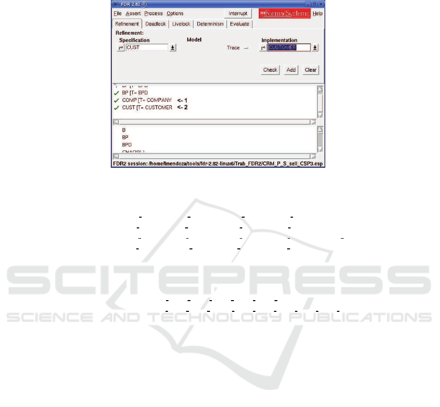
Fig.3. FDR2 screenshot.
Ω
Cus
∩ ΩCom = ∅ (8)
Ω
Cus
= {msg.cu s1.in, msg.cu s1.last, msg.cu s2.in, msg.cu s2.last, msg.cancel.can,
msg.cu s5.in, msg.cu s5.last, msg.cu s6.in, msg.cu s6.last}
Ω
Com
= {msg.co s1.in, msg.co s1.last, msg.co s2.in, msg.co s2.last, msg.co s3.in,
msg.co s3.last, msg.co s8.in, msg.co s8.lastmsg.co s8.last}
2. The labelling sets of both components, L(Cus) and L(Com), are disjointed, which
can also be verified as follows:
L(Cus) ∩ L(Com) = ∅ (9)
L(Cus) = {start.1, cu s1, cu s2, cu s3, cu s4, cu s5, cu s6, xgate.1, end.1, abort.1}
L(Com) = {start.2, co s1, co s2, co s21, co s3, co s4, co s5, co s6, co s7, co s8,
agate.1, agate.2, end.2, abort.2}
Having verified that the assertions (7), (8), and (9), are true, we conclude that Cus and
Com are “composable”. By Theorem 1 (see section 3), we have:
(Cus|[αCuskαCom]|Com) \{| msg |} |= φ
Cus
∧ φ
Com
and because
P SS = (Cus|[αCuskαCom]|Com)\{| msg |} and φ
P SS
= φ
Cus
∧ φ
Com
,
we have
P SS |= φ
P SS
Finally, we have obtained the verification of a BPTM corresponding to the Prod-
uct/Service Sell BP from their verified local BP, Customer and Company.
5 Conclusions
In this paper we have presented and validated FCVA for compositional software verifi-
cation from independently verified individual components and its instantiation to spec-
ify and verify the BPTM derived from BPs supported by an EIS. The local BPs are
68

modelled as CSP+T process terms, since it supports syntactical composition of process
terms by the concurrent composition operator. Also a timed semantics of BPMN de-
fined in terms of CSP+T formal specification language is presented to complement the
FVCA, which allows us to detail the response times of activities and tasks, temporal
constraints referring to task communication and collaboration, and the valid time span
to capture exception flows, according to the expected behaviour of BPs. We have shown
the value and practicality of our approach by means of its application to a real–life
example in the field of CRM with timed collaboration requirements. Thus, the com-
plete BPTM, derived from its core participants, can also be proved correct by means of
the formal language CSP+T that allows local verification results of CSP+T syntactical
terms —representing individual local BPs— to be exported into the entire global BP
verification, which is obtained as a concurrent composition of process terms. MC was
used by passing the CSP+T terms through FDR2 to prove the correctness of global BPs.
Future and ongoing work will focus on the application of FCVA and the timed
semantics of BPMN proposed to BPTM verification case studies; our future work will
consist of doing in–depth research on the verification of these specifications, and to
obtain automatic tool support for BPM by using state–of–the–art verification tools.
References
1. OMG: Business Process Modeling Notation – version 1.2. Object Management Group,
Massachusetts, USA (2009)
2. Wong, P., Gibbons, J. In: A Process Semantics for BPMN, LNCS 5256: Proc. 10th Int. Conf.
on Formal Engineering Methods ICFEM. Springer–Verlag, Berlin (2008) 355–374
3. Capel, M., Mendoza, L. In: Automatic Compositional Verification of Business Processes,
LNBIP 24: Enterprise Information Systems. Springer Berlin, Heidelberg, Germany (2009)
479–490
4.
ˇ
Zic, J.: Time–constrained buffer specifications in CSP+T and Timed CSP. ACM Transaction
on Programming Languages and Systems 16 (1994) 1661–1674
5. B´erard, B., Bidoit, M., Finkel, A., Laroussinie, F., Petit, A., Petrucci, L., Schnoebelen, P.,
McKenzie, P.: Systems and software verification: model-checking tech. and tools. (1999)
6. Morimoto, S. In: A Survey of Formal Verification for Business Process Modeling, LNCS
5102: Proc. 8th International Conference on Computational Science (ICCS 2008). Springer–
Verlag, Berlin (2005) 514–522
7. Demri, S., Sattler, U.: Automata-theoretic decision procedures for information logics. Fun-
dam. Inf. 53 (2002)
8. Mendoza, L., Capel, M.: Algorithm proposal to automata generation from CCTL formulas.
Technical report, University of Granada (2008)
9. Mendoza, L., Capel, M., P´erez, M.: Compositional verification of business processes mod-
elled with BPMN. In: Proc. 12th Int. Conf. on Enterprise Information Systems (ICEIS 2010),
Set´ubal, Portugal, INSTICC Press (2010) to appear
10. R¨uf, J., Kropf, T.: Symbolic model checking for a discrete clocked temporal logic with in-
tervals. In: Proceedings of the IFIP WG 10.5 International Conference on Correct Hardware
Design and Verification Methods. (1997)
11. Mendoza, L., Capel, M.: Procedure proposal to automata generation from CSP+T process
terms. Technical report, University of Granada (2009)
12. Formal Systems (Europe) Ltd: Failures–Divergence Refinement – FDR2 User Manual. For-
mal Systems (Europe) Ltd, Oxford (2005)
69
