
Object Interaction as a Central Component
of Object-oriented System Analysis
Oksana Nikiforova
Riga Technical University, Faculty of Computer Science and Information Technology
Kalku 1, LV-1658, Riga, Latvia
Abstract. An increasing impact of system modeling in software development
facilitates a vision of software development methodology. Currently one of the
leading positions has OMG and its solution for system abstraction, modeling,
development, and reuse – Model Driven Architecture (MDA). A key compo-
nent of system modeling under principles of MDA is Unified Modeling Lan-
guage (UML), which defines several kinds of diagrams and their notation. Sys-
tem modeling is an important part of system analysis and design, where MDA
proposes to use means of automatic code generation. UML offers to use system
presentation as interacting objects and offers to model two kinds of object inte-
raction diagram, namely, sequence and communication. The paper focuses on
investigation of analysis, modeling, and design of object interaction and dis-
cusses the ability to increase the level of formalization in modeling of object in-
teraction.
1 Introduction
Model Driven Architecture (MDA) [1] is an OMG initiative built on principles of
abstraction, modeling, reuse, and patterns, to provide software developers with an
approach to identify and classify all of the system development activities and offer
the usage of models and model transformations as a foundation for system develop-
ment within every group of activities. System analysis results in platform independent
model (PIM), which is then refined and transformed into platform specific model
(PSM) to support the design activities in terms of software components. Then PSM is
used to define code components and system implementation [2].
The primary benefit of MDA is to give a big-picture view of the architecture of the
entire enterprise [3]. Any new system should fit into the existing data and platform
configuration. In order to use the MDA approach, the developer should have a com-
mon modeling system and a language to describe PIMs. A key component of PIM
modeling is another OMG’s standard—Unified Modeling Language (UML) [4].
UML defines a notation for a set of diagrams used for modeling of different aspects
of the system (i.e., static and dynamic ones). A central part of static modeling in
UML is class diagram, which defines a general structure of the system and serve as a
basis for the development of software architecture. Class diagrams are investigated
quite well in different researches. Author of the paper also paid attention to this and
published the results in [5], [6], [7], [8], [9]. According to modeling of system’s
Nikiforova O. (2010).
Object Interaction as a Central Component of Object-oriented System Analysis.
In Proceedings of the 2nd International Workshop on Model-Driven Architecture and Modeling Theory-Driven Development, pages 3-12
DOI: 10.5220/0003023000030012
Copyright
c
SciTePress

dynamic, exactly problems of its definition are the reason why MDA goals are not
achieved yet [10].
The central part of modeling of system’s dynamic is the construction of object in-
teraction, where two UML diagrams—sequence and communication—are used to
present system’s behavior [4]. UML sequence diagrams allow to describe interactions
between system objects and actors of its environment. Sequence diagram describes
sequences of communications that may occur in the course of a run of the system and
traces the messages that are exchanged during this run. Sequence diagram is a popu-
lar notation to specify scenarios of the processing of operations as its clear graphical
layout gives an immediate intuitive understanding of the system’s behavior [11].
UML sequence diagram is stated as one of the ambiguous UML diagrams [12], with
an implicit and informal semantic that designers can give to basic sequence diagram
as a result of this conflict [13], [14], [15]. In turn, collaboration diagrams are another
means for representing the interactions and relationships between objects. Unlike
sequence diagram, however, collaboration diagram does not focus on the timeline of
interaction, but on the structural connections between collaborating objects.
The research object of the paper is UML sequence diagram. The goal of this paper
is to investigate a strategy of definition of main elements of object interaction and to
find an ability to base this definition on the elements of two-hemisphere model, which
is already used for definition of object classes and structure of its collaboration in
author’s previous papers [7], [8], [9].
The paper is structured as follows. Modeling strategy of UML diagrams is investi-
gated in Section 2. Schema of general transitions among UML diagrams is created
based on the examination of object-oriented system analysis. Section 3 offers to use
two-hemisphere model as a foundation for definition of elements of sequence dia-
grams. Overall idea of definition of transformation from business process model and
related concept model into UML sequence diagram is shown in terms of graph trans-
formations. Section 4 illustrates an example of the proposed ideas in a case study.
Section 5 makes several conclusions on the research.
2 Object Interaction under Object-oriented System Analysis
The standard notation for system modeling in object-oriented software development
is Unified Modeling Language (UML) [4]. UML diagrams give a possibility to model
different aspects of software system, but UML is just a notation and does not provide
methodological instructions on how to model the system. Developer needs informa-
tion about the system being developed in a form, which gives an ability to transform
this information into UML diagrams.
Therefore, the development of a software system starts with the gathering of busi-
ness information and its further presentation in a form suitable for system modeling.
In classical approach, this information is presented in a form of processes to be per-
formed and information flows required for process execution. Then this presentation
of business information should be transformed into software system model, which
under object-oriented manner for software development requires to identify objects
from problem domain and to share responsibilities of operation execution between
4

these objects.
UML sequence diagram shows objects, their lifelines, and messages to be sent by
objects-senders and performed by object-receivers. Sequence diagram is used to
present the dynamic aspect of the system, which in object-oriented approach is ex-
pressed in terms of message transfer among objects. The dynamic of interactions is
defined by an ordering of the message sending and receiving actions. It serves as a
basis for the definition of operations performed by objects to be grouped into classes,
as well as to present and to verify the dynamic aspect of class state transition.
The problem, which is widely researched in the area of modeling of object interac-
tion, is formal transitions among models presented at different levels of system ab-
straction. The transition from problem domain into system implementation expressed
in terms of objects is required in object-oriented software development using MDA
principles [1]. Nothing new is in the definition of classes and attributes without rela-
tionships among them. Software development techniques and methodologies propose
several methods to indicate classes in problem area or in initial models. The process
of class diagram development defined by James Rumbaugh yet in 1991 for Object
Modeling Technique [16] still is one of the best approaches for identification of
classes at system domain level, real-world operations on the domain objects, as well
as state diagrams showing the life histories of domain objects. Ivar Jacobson in [17]
together with Grady Booch and James Rumbaugh in [18] has offered the definition of
system use-cases. Since that, one of the powerful groups of system modelers can be
called as use case-oriented society of software developers. Several more researches
under this direction are [3], [19], etc. In general, the process, which uses use-cases as
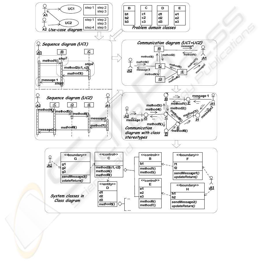
a basis for modeling of object interaction, is shown in Fig. 1.
Use-case-oriented approach is based on an effort to define use-cases and users of a
system, as well as to describe the usage of a system by detailed scenarios. It, in turn,
provides a basis to define steps for object interaction and sharing of responsibilities
among domain classes. Deeper analysis of object communication gives a possibility
also to define class stereotypes, which, in turn, will be important components of a
software design.
System developers often ignore the “use-case-driven” prescription that permeates
much of the UML literature, making limited or no use of either use-case diagrams or
textual use-case descriptions [20]. Many organizations are using different tools for
business process analysis and, therefore, have complete and consistent models of their
organizational structure, responsibilities of employer, business processes, as well as
the structure of documentation flows—in other words, well-structured initial business
knowledge [6]. Therefore, the class diagram development in a more formal way can
be based on the initial business knowledge.
So far, another group of software developers prefer to use business process model-
ing at the initial stage of system analysis. We can call them as business process
oriented society of software developers, such as [21], [22]. Anyway, process-oriented
developers are also using use-cases. However, an identification of use-cases is per-
formed in much more formal way than just based on user stories or general domain
descriptions. As far as we have two main concepts for analysis of problem domain,
which are process and data, it is possible to identify several approaches, which are
more oriented on data to be created, updated, and stored during software development
(such as [23]). Entity-relationship modeling is a semiformal data-oriented technique
5
for specifying software systems. It has been widely used for over 30 years for speci-
fying databases [24]. So called data-oriented developers are working in correspon-
dence with the definition of data structure and operations to be performed with data
are of less importance. Of course, operations are needed to access the data, and the
database should be organized in such a way as to minimize access time. Nevertheless,
the operations performed on the data are less significant. On its merits, we even can
assume that software developed in this way is not developed in object-oriented man-
ner and here the role of object interaction is secondary.
Fig. 1. Class diagram development, based on definition of use-cases.
Author assumes that the concatenation of data (concept) model with process dia-
gram allows to identify classes, their attributes, relationships with other classes and
even more—operations of classes. The idea of common consideration of both models
is known; nevertheless, the usage of combination of business process model and
concept model for definition of class responsibilities and relationships among classes
6

in object-oriented approach was not widely published. Author of the paper in [25]
proposes how classes and its object’s operations can be defined based on so called
two-hemisphere model [6], which essence is two interrelated models. The next Sec-
tion examines the abilities of two-hemisphere model for definition of elements of
object interaction in terms of UML sequence diagram.
3 Two-hemisphere Model as a Base for UML Sequence Diagram
The core of this paper is a hypothesis that business process and concept model con-
tains enough information for sharing responsibilities among objects and can serve as
a base for definition of object interaction by using of UML sequence diagram. Two-
hemisphere model [6] contains information about business processes and concepts
and has already been used for representation of object interaction with UML commu-
nication diagram in [7], where only static view of the system is investigated and an
ordering of message sending and receiving is missed. Now, author tries to find de-
pendency between elements of two-hemisphere model and elements of UML se-
quence diagram, especially in its timing aspect.
A nature of transition from business information into object interaction is found in
the definition of which processes have to be performed in the system and which per-
former will execute exact process at the software level of system modeling. In order
to identify a performer of the process at the software level of system presentation the
process has to be analyzed with the aim to define a software operation to execute the
process, as well as to notice the object to perform this operation.
So far, two general steps can be defined for object-oriented system analysis. The
first one is to identify objects themselves. This task is solved in [16], [19]. In general,
the analysis of entity relationship [24] can serve as a foundation for object identifica-
tion of the software system. The second activity of object-oriented system analysis is
so called “sharing of responsibilities” among objects, which is not so trivial and is
stated for solving by the author of the paper. The main task to be defined is which
operation will be executed by which object in which time sequence.
Two-hemisphere (2HMD) approach proposes to start process of software devel-
opment based on two-hemisphere problem domain model, where one model reflects
functional (procedural) aspects of the business and software system, and another
model reflects corresponding concept structures [5]. The co-existence and interrela-
tedness of these models enables the use of knowledge transfer from one model to
another, as well as the utilization of particular knowledge completeness and consis-
tency checks [6]. [8] defines the way on how the elements of business process model
and concept model are transformed into elements of UML communication diagram,
as well as their further transformation into elements of class diagram using direct
graph transformations. The arcs of graph of business processes are transformed into
nodes of UML communication diagram. The nodes of business process graph are
transformed into the arcs of UML communication diagram, which is redrawn in ac-
cordance with conventions of UML notation. In other words, events of process model
defined by data types from concept models became objects in UML communication
diagram. And processes of process modelserve as a basis to define corresponding
messages requiring to execute certain operation (to perform the process). The follow-
7
ing approach and all the transitions are defined in details in [8], [9].
The analysis of two-hemisphere model proposed in [7] may lead to the conclusion
that the notational conventions of UML communication diagram are more suitable for
definitions of formal transformations of two-hemisphere model into object interaction
and then into class diagram, than the application of UML sequence diagram. There-
fore, the UML communication diagram was used for transitions between graphs and
for definition of classes to be responsible for exact message sending and operation
execution. However, the aspect of time sequence, which is a component of UML
sequence diagram, is not shown in communication diagram (i.e., is missed in this
case). This paper focuses on the possibility to save time aspect in transition from two-
hemisphere model into UML sequence diagram in accordance with an initial idea
presented in [5].
Sequence diagram shows interaction of objects for execution of concrete use-case
or business function expressing time aspect as a main focus of modeling. Sequence
diagram consists of objects, their lifelines, and messages which they have to send to
other objects. Object identification is based on the analysis of noun phrases in prob-
lem domain description [16], where it is presented in the form of two-hemisphere
model and contains the information about problem domain, where noun phrases are
defined for events (arcs) of business process model and concepts of concept model
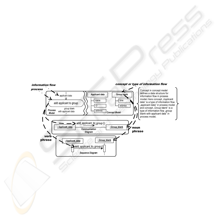
(see Fig. 2). Therefore, it is possible to suggest that description of an event in busi-
ness process with its defined data structure in concept model can serve as a basis for
identification of object in sequence diagram.
Fig. 2. Analysis of verb and noun phrases in two-hemisphere model and related object
interaction.
The transformation of two-hemisphere model into communication diagram is per-
formed in a direct way by graph transformation, where arcs of graph of business
processes are transformed into the nodes of graph of object communication. The same
assumption can be applied for the definition of objects in sequence diagram—object
sender will be defined by incoming arc of exact process in the model of business
processes and object-receiver will be defined by outgoing arc of exact process in the
model of business processes (Fig.2). The description of an event in business process
with its defined data structure in concept model can serve as basis for definition of
8
object, which is a node of its lifeline. The analysis of verb phrase (Fig. 2) makes it
possible to suggest that the name of business process has to be a base for the defini-
tion of message of sequence diagram to be performed by object-receiver of this mes-
sage. Therefore, a message defined for execution of exact process in business process
diagram will be sent by the object defined in the incoming arc of exact business
process and received by the object in the outgoing arc of exact business process.
Author’s experiments on the assumptions proposed above have found the variety
of combinations of input and output events for business processes. The problem of
this variety is that it is not always possible to define the elements of sequence dia-
gram in direct way. Several cases, where process has two incomes, require an investi-
gation on the definition of the object-sender of message.
Whereas the construction of object communication and further definition of class
structure was avoided to solve this problem, the main aspect was stated as according
to the aspect of who will be the object-receiver of the method. As for sequence dia-
gram, this variety gives a base for definition of so called interaction frames [4]. Sev-
eral examples of them are demonstrated in the next section, which presents practical
example on using of the defined transformations for pupil application to driving
school.
4 An Illustrative Example of Two-Hemisphere Model Application
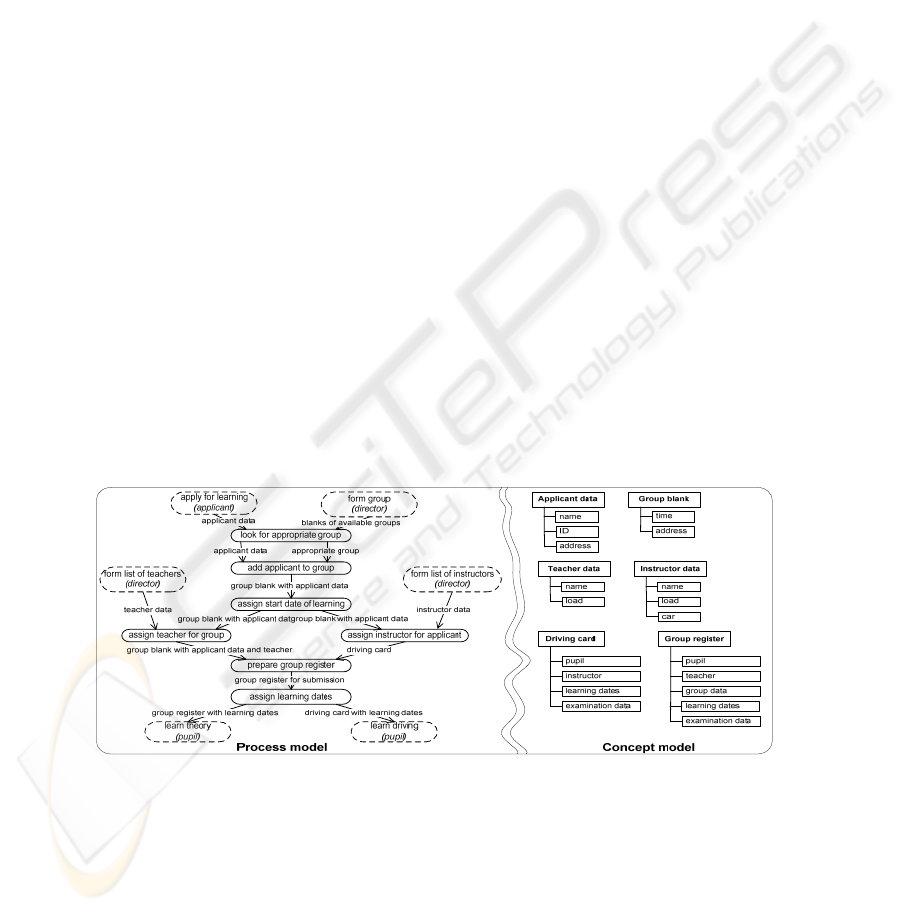
The simplified version of the business process for the application of the pupil of the
driving school is reflected in two-hemisphere model shown in Fig. 3. The sketch of
the corresponding sequence diagram is shown in Fig. 4. Several fragments of the
sketch of the sequence diagram allow discussing the ability to define a more compli-
cated set of elements, such as interaction frames for parallel operating and alterna-
tives, different types of messages, etc.
Fig. 3. Two-hemisphere model of the application of pupil to the driving school.
For example, the fact that the Y axis (time axis in both diagrams) and semantic con-
ventions for process modeling that process can be performed when all incoming
information flows are generated from their execution processes. Author assumes
that process “form list of teachers” and “form list of instructors” with all their
9
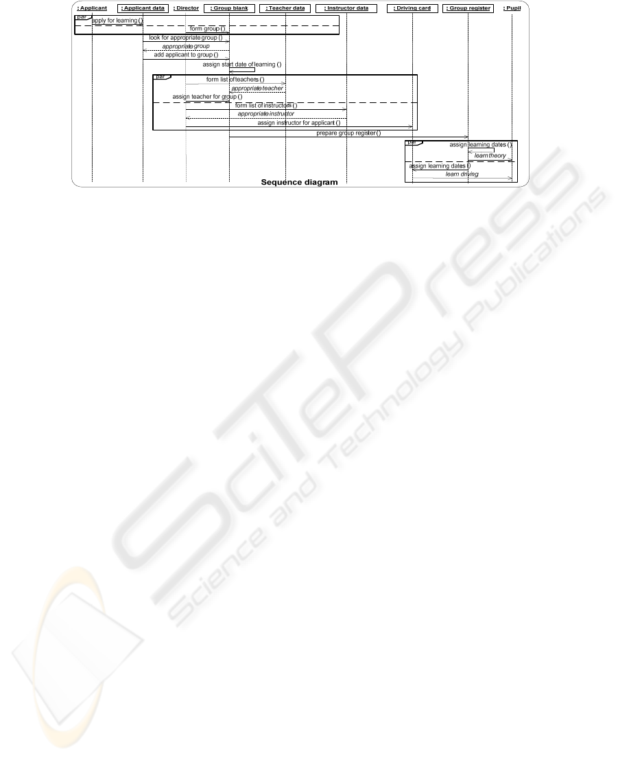
Fig. 4. The corresponding UML sequence diagram.
successors, which are two parallel fragments in process model, seem to be disjunctive
fragments in the resulting UML sequence diagram.
Therefore, the corresponding sequence of message sending is taken into parallel
interaction frame. In addition, the diagram starts with two messages sent at the same
time. However, system requires that both processes have to be completed before the
process “look for appropriate group” should start. For now, the interaction frame for
parallel messages is arranged for both messages to be sent, but this states a set of
possible directions for future research on application of two-hemisphere model for
object-oriented modeling of the system in UML.
One more interesting fragment of object interaction is the process “assign learning
dates.” The fact that the process has two outgoing information flows, which are de-
fined as ones of different data type, lets author to assume that control message “assign
learning dates” should be sent to both objects—“group register” and driving card.” In
this example, this assumption is proved also for several more sophisticated real world
examples, where all the analogical fragments give the same result.
5 Conclusions
The purpose of a model-driven approach is to structure the modeling process, provid-
ing the base of research directions, which explain how to consider general models, as
well as to relate them with a more specific information about platforms, performance
and so on. Two-hemisphere approach is already successfully applied for encapsula-
tion of attributes and methods into system classes, as well as the definition of rela-
tionships between classes. The ideas presented in this paper are a step forward of the
author’s investigations in the application of two-hemisphere model for software sys-
tem development in object-oriented manner and the generation of different elements
of system model viewing the system from different aspect.
Thus, the contribution of the paper can be summarized as follows. First, author in-
vestigates the process of object-oriented system analysis and defines commonly used
transitions among UML diagrams and its elements, which summarizes different ap-
proach for modeling of problem domain in object-oriented manner.
10

The main achievement of the research is that two-hemisphere model is examined
on the ability to be used for definition not only for structural elements of developed
system, but also as a base for definition of system behavior. This is due to two-
hemisphere model originally contains both aspect of problem domain definition, and
an effort to define behavioral elements of UML diagrams is an evolutionary step
forward in complete usage of elements of two-hemisphere model for software system
definition.
And additionally, as far as two-hemisphere model driven approach introduces
another (additional) modeling step between system specification and software devel-
opment, the question is whether the benefits of formal transformation prevail or not.
But modeling of business processes and preliminary data structure is not new strategy
for requirement analysis and companies are common with business process modeling
techniques or at least they employ particular business process description frame-
works. This fact and existence of many commercial business modeling tools (such as
ARIS, IBM products, Sparx Software Architect, etc.) and their open source analogues
are a strong motivation to base software development on the business process model
rather than on any other soft or hard models. Therefore, the formal transformation of
two-hemisphere model into UML diagrams shall step in and try to acquire software
requirements.
A tool for generation of class diagram from two-hemisphere model is developed
and presented in [7]. The refinement of the tool with an ability to define elements of
object interaction in the form suitable for UML diagramming tools can be defined as
a step for author’s future research.
Acknowledgements
The research reflected in the paper partly is supported by Grant of Latvian Council of
Science No. 09.1269 “Methods and Models Based on Distributed Artificial Intelli-
gence and Web Technologies for Development of Intelligent Applied Software and
Computer System Architecture.” The research reflected in the paper partly is sup-
ported by Riga Technical University in cooperation with Microsoft under the project
No. FLPP-2010/20 “Research of Principles of Model Driven Architecture in Software
Development Tools.”
References
1. MDA Guide Version 1.0.1 – http://www.omg.org/docs/omg/03-05-01.pdf, 2003, achieved
September 2009
2. Siegel, J.: Developing in OMG’s Model-Driven Architecture. OMG document omg/01-12-
01. (2001) http://www.omg.org/mda/papers.htm
3. Satzinger, J., W., Jackson, R., B., Burd, S., D.: Object-Oriented Analysis and Design with
the Unified Process. Thomson Course Technology (2005)
4. OMG, Unified Modeling Language: Superstructure, v. 2.2 – http://www.omg.org/spec/
UML/2.2/Superstructure/, achieved September 2009
5. Nikiforova, O.: General Framework for Object-Oriented Software Development Process.
11

Scientific Proceedings of Riga Technical University. Series–Computer Science, Applied
Computer Systems, 13 vol., RTU Riga (2002) 132–144
6. Nikiforova, O., Kirikova, M.: Two-Hemisphere Model Driven Approach: Engineering
Based Software Development. In: 16th International Conference Advanced Information
Systems Engineering. Persson A., Stirna J. (Eds.), LNCS 3084, Springer (2004) 219–233
7. Nikiforova, O., Pavlova, N., Grigorjev, J.: Several Facilities of Class Diagram Generation
from Two-Hemisphere Model. In: 23rd International Symposium on Computer and Infor-
mation Sciences, IEEE Xplore (2008) 1–6
8. Nikiforova, O.: Two Hemisphere Model Driven Approach for Generation of UML Class
Diagram in the Context of MDA . In Huzar, Z., Madeyski, L. (eds.) e-Informatica Software
Engineering Journal, Vol. 3, Issue 1, Wrocław University of Technology, Oficyna Wy-
dawnicza Politechniki Wrocławskiej, Wrocław, Poland (2009) 59–72
9. Nikiforova, O.: System Modeling in UML with Two-Hemisphere Model Driven Approach,
In: Scientific Journal of Riga Technical University, 5
th
Series – Computer Science, Applied
Computer Systems, RTU (2010)
10. Pastor, O., Molina J., C.: Model-Driven Architecture in Practice: A Software Production
Environment Based on Conceptual Modeling, Springer (2007)
11. Sibertin-Blanc, C. Hameurlain, N., Tahir, O.: Ambiguity and structural properties of basic
sequence diagrams. In: Innovations System Software Engineering, Springer (2008) 275–284
12. Sibertin-Blanc, C., Tahir, O., Cardoso, J.: Interpretation of UML sequence diagrams as
causality flows. Advanced distributed systems, 5th international school and symposium
(ISSAD). Lecture Notes in Computer Science, Vol. 3563. Springer (2005) 126–140
13. Alur, R., Etessami, K., Yannakakis, M. Inference of message sequence charts. Proceedings
of the 22nd international conference on software engineering. ACM Press (2000) 304–313
14. Uchitel, S., Kramer, J., Magee, J.: Detecting implied scenarios in message sequence chart
specifications. Proceedings of the 9th European software engineering conference and 9
th
ACM SIGSOFT international symposium on the foundations of software engineering
(ESEC/FSE’01). ACM New York (2001) 74–82
15. Aredo, B.D.: A framework for semantics of UML sequence diagrams in PVS. J Univers
Comput Sci (JUCS). – 8(7) (2002) 674–697
16. Rumbaugh, J., Blaha, M., Premerlani, W., Eddy F., Lorensen W.: Object Oriented Model-
ing and Design. Englewood Cliffs, Prentice-Hall New Jersey (1991)
17. Jacobson, I.: Object Oriented Software Engineering: A Use-case Driven Approach. Addi-
son-Wesley Professional (1992)
18. Jacobson, I., Booch, G., Rumbaugh, J.: The Unified Software Development Process. Addi-
son-Wesley (2002)
19. Larman, C.: Applying UML and Patterns: An Introduction to Object-Oriented Analysis and
Design. Prentice Hall New Jersey, 3rd edn (2005)
20. Dobing, B., Parsons, J.: Dimensions of UML Diagram Use: A Survey of Practitioners, IGI
Global (2008)
21. Havey, M.: Essential Business Process Modeling. O'Reilly Media (2005)
22. Jeston, J., Nelis, J.: Business Process Management. 2nd edition: Practical Guidelines to
Successful Implementations, Butterworth-Heinemann (2008)
23. Toby, J., Teorey, S., S., Lightstone, T. N., Jagadish H.,V.: Database Modeling and Design:
Logical Design, 4th Edition. In: The Morgan Kaufmann Series in Data Management
Systems, Morgan Kaufmann (2005)
24. Chen, P.: The entity relationship model – towards a unified view of data. ACM Trans.
Database Systems, 1 (1976) 9–36
25. Nikiforova, O., Pavlova, N.: Foundations on Generation of Relationships Between Classes
Based on Initial Business Knowledge. In: 17th International Conference on Information
Systems Development, Springer-Verlag, New York (2008) 289-297
12
