
GMPath - a path language for navigation, information
query and modification of data graphs
Karsten Wendt, Matthias Ehrlich, and Ren
´
e Sch
¨
uffny
Technische Universit
¨
at Dresden, Institute of Circuits and Systems
01062 Dresden, Germany
Abstract. This paper presents a newly developed path language named GMPath
intended to ease the navigation, information query and modification of general,
directed model graphs for the FACETS Stage 2 Large Scale Reconfigurable Neu-
ral Hardware Simulator. Furthermore it introduces the reader to the relevant as-
pects of the FACETS system and its software framework accordingly.
1 Introduction
The project Fast Analog Computing with Emergent Transient States – FACETS [1] aims
at the exploring of various computational aspects of biological neural networks. This
encompasses the development of a novel neural hardware system as a joined effort
of research groups of the Ruprecht-Karls-Universit
¨
at Heidelberg and the Technische
Universit
¨
at Dresden. [2][3]
The complexity of such a hardware system also requires an adequate software sys-
tem, to configure, control and validate results. A graph based model description was
developed, representing all aspects of the system. To interact with and query the mod-
els, the description is extended by a query interface.
This paper is split into three sections. The first section describes the current state
of the FACETS systems, focusing modelling and mapping issues. Embedded in the
FACETS software framework, the graph model itself will be introduced. The next sec-
tion characterizes the motivation and requirements for the development of the path lan-
guage GMPath and distinguishes it from existing query languages. Afterwards, basing
on a meta description the grammar of the language is defined and the semantics of its
elements are explained. Illustrating the use of GMPath the last section provides several
examples, based on a given concrete graph model by explaining some queries in more
detail.
2 Current State of the FACETS Systems from the Mapping
Viewpoint
The systems involved in the FACETS mapping and configuration process can be sep-
arated into the hardware model on the one hand and the biological model on the other
hand, which should be simulated on the hardware system after the configuration. To
Wendt K., Ehrlich M. and Sch
¨
uffny R. (2010).
GMPath - A Path Language for Navigation, Information Query and Modification of Data Graphs.
In Proceedings of the 6th International Workshop on Artificial Neural Networks and Intelligent Information Processing, pages 33-40
Copyright
c
SciTePress
encompass the modelling and mapping problem a so called graph model is used and in-
tegrated in the FACETS software framework. The models and the software framework
are characterized in the following sections.
2.1 Biological Model
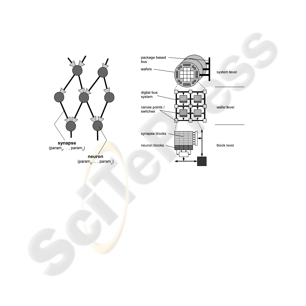
The biological systems, intended to be mapped to the FACETS hardware, can be con-
sidered as networks of neurons and synapses. A neuron is connected to a number of
synapses and characterized by a set of parameters. A synapse connects a source and
a target neuron and is as well assigned to parameters. The illustration of an example
model is shown in figure 1.
2.2 Hardware Model
Fig.1. Example of a biological system with
7 neurons and 11 synapses.
Fig.2. Hierarchical view of the FACETS hardware
system
The current FACETS Stage 2 system [2] consists of analog modeled IF (integrate-
and-fire) neurons and synapses, which implement a STDP (spike-time-dependency-
plasticity) mechanism. The neuron’s and synapses’ behavior is defined by a set of con-
figurable parameters.
A hierarchical view of the system is illustrated in figure 2. The neural signals gen-
erated by the hardware neurons (block level), are propagated via a complex transfer
network to be fed as stimuli into the hardware synapses or to be recorded externally. It
is also possible to generate external stimuli and apply those to the neural network.
The transfer network is designed to provide as much topological flexibility as pos-
sible, while complying with the technological constraints. Generated neural signals are

encoded blockwise to a digital bus- (wafer level) and an overlaying package based net-
work (system level). These contains configurable cross points and switches, duplicating
and routing the signals to their destined synapses. After decoding the signals stimulate
their assigned hardware dendrites, whose combinations form the receiving neurons. [3]
Due to the system complexity and network properties several mapping and configura-
tion constraints result, forming a multi-criteria optimization problem, which will not be
discussed here further. [8]
2.3 FACETS Software Framework
The FACETS software framework consists of
– a collection of programs to carry out experiments (e.g. comparative experiments on
neural software simulators and the FACETS hardware [4]),
– a database of benchmarks provided by FACETS partners (e.g. [5], [6]),
– a system simulation of the FACETS hardware [7],
– software for mapping and configuration [9],
– and visualization and analyzation tools. [8]
As presented in previous work [10] we developed a model, integrating the FACETS
model descriptions for the mapping, configuration, visualization and analyzation soft-
ware. Based on a graph, it stands for an universal data representation for the software
framework. The mapping, routing and configuration algorithms retrieve their informa-
tion from this Graph Model (GM), process, transform them and write back the results.
Furthermore the decentralized structure makes the model suitable for parallelization. A
summarized model characterization is given in the next section to clarify the structure
whereon the newly developed query language GMPath (see 3) bases.
2.4 The Graph Model to Navigate
The graph model G = (V, E), basing on a hyper graph [11] [12], consists of single
nodes v
i
∈ V , that may hold a name or a value as a data item respectively. The nodes
can be assigned to each other by three types of directed single edges e
i
∈ E as shown
figure 3:
– hierarchical edges - modelling a hierarchy of two nodes, i.e. to represent a container-
component relationship
– named edges - modelling a labeled relationship between two nodes
– hyper edges - assigning a named edge to a node, i.e. to model a detailed description
of a node-node relationship.
Because of its structure the model is fully navigable, which means every node or
edge is reachable from every position in the graph. So it is possible to create flexi-
ble models with respect to the biological networks and hardware system complexity,
although it consumes more memory and setup time than more compact descriptions.
Given this model the biological and the hardware system can be described as two
combined graphs G
B
= (V
B
, E
B
) and G
H
= (V
H
, E
H
) respectively, also containing
meta information, e.g. algorithm configurations and results. The model transformation
is not discussed here further [9] [10].
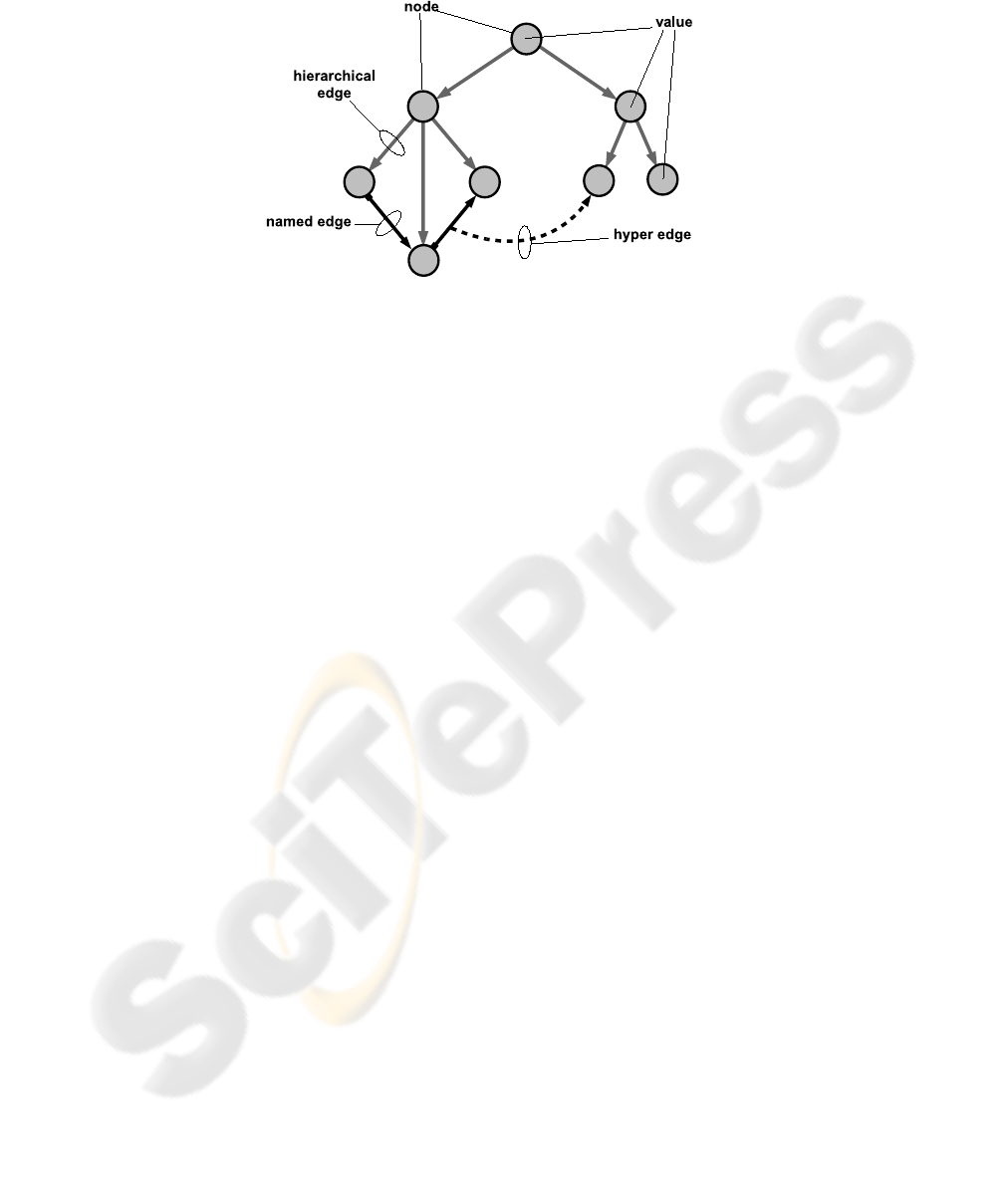
Fig.3. Graph Model (example)
3 GMPath - A Language for Graph Model Navigation
The flexible and universal use of the GM by placing and routing algorithms, configura-
tion, visualization and analyzation tools as well as the user defined modifications during
run-time calls for an adequate and multi-purpose interface. The main requirements are:
– access from every node or edge as entry point
– step by step navigation along all elements (nodes and edges) follwing a path
– list based results, assignable to variables
– GM modification support
Inspired by the XML path language XPath [13] we developed a textual interface,
named GMPath, to navigate in and retrieve information from the GM by entering at
any node or edge, and address parts of it locally. Thus it can also classified as Lokator-
sprache.
Fig. 4 shows the logical environment of a GM node or edge respectively. Each adja-
cent element requires to be accessible within one ”separation step”, i.e. one basic navi-
gational operation. Following the hierarchical structure the navigational focus should be
able to shift from the current node (node value) up- or downward to the superior node
or the subjacent nodes. Regarding the named and hyper edges it should be possible to
move along these connections forward and backward to their start and end nodes.
Since all GMPath queries return result lists, containing the matching GM elements,
they should be storable to variable names. By selecting these names, all nodes and edges
can be used as an entry point for a new GMPath query. Furthermore GMPath requires
to be able to address GM elements unambiguously to create new nodes and edges by
this way. Thus, paths can built up during run-time by the software tools and processed
with implemented API functions, parsing the paths and returning the result elements.
This provides a dynamic interface to retrieve data from and manipulate the GM.
In the following sections the characteristics of GMPath and the query language
XPath will be compared before the grammar and semantics are defined and explained
consecutively.
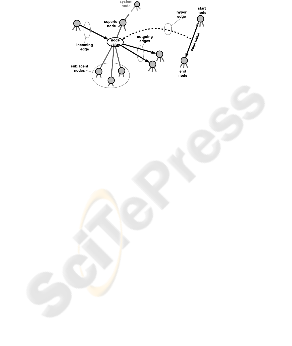
Fig.4. Logical environment of GM nodes and edges
3.1 Comparison to XPATH
As shown in the previous section the used data model is much leaner than a XML
document, it does not include attributes and types of the contained data. However it is
possible to interconnect nodes semantically via named edges to model distinct relation-
ships between GM elements.
In opposition to XPATH GMPath does not distinguish between localization steps,
axes tests or predicates, it only performs navigation steps along the GM structure with
a matching result. Tests on subjacent nodes have to be executed as tests of reachability,
comparisons of their assigned values are realized by localized GMPath queries.
In addition to the navigation along the hierarchy, known as axes in XPATH, local-
ization or separation steps for named and hyper edges are necessary, to navigate strictly
along the semantic relationships beside the hierarchical structure.
Furthermore in Creation Mode GMPath can be used to generate nodes and edges
by addressing them unambiguously.
3.2 Grammar and Semantics
The grammar of GMPath is defined with the GOLD Meta-Language and written, tested
and validated in the Gold Parsing System [14]. The meta-description uses the following
elements to specify the GMPath grammar:
– terminal symbols, represented through Regular Expressions
– rules, using the Backus-Naur Form
– character sets, based on set notation
Terminal Symbols: As shown in Tab. 1 GMPath contains five terminal symbols that
cover the comment line (%) and two different general entry points (SystemNode and
HERE) for the next query to start. Furthermore a wildcard symbol (∗) encapsulates
groups of GM elements without naming them and identifiers to store and represent node
and edge lists.
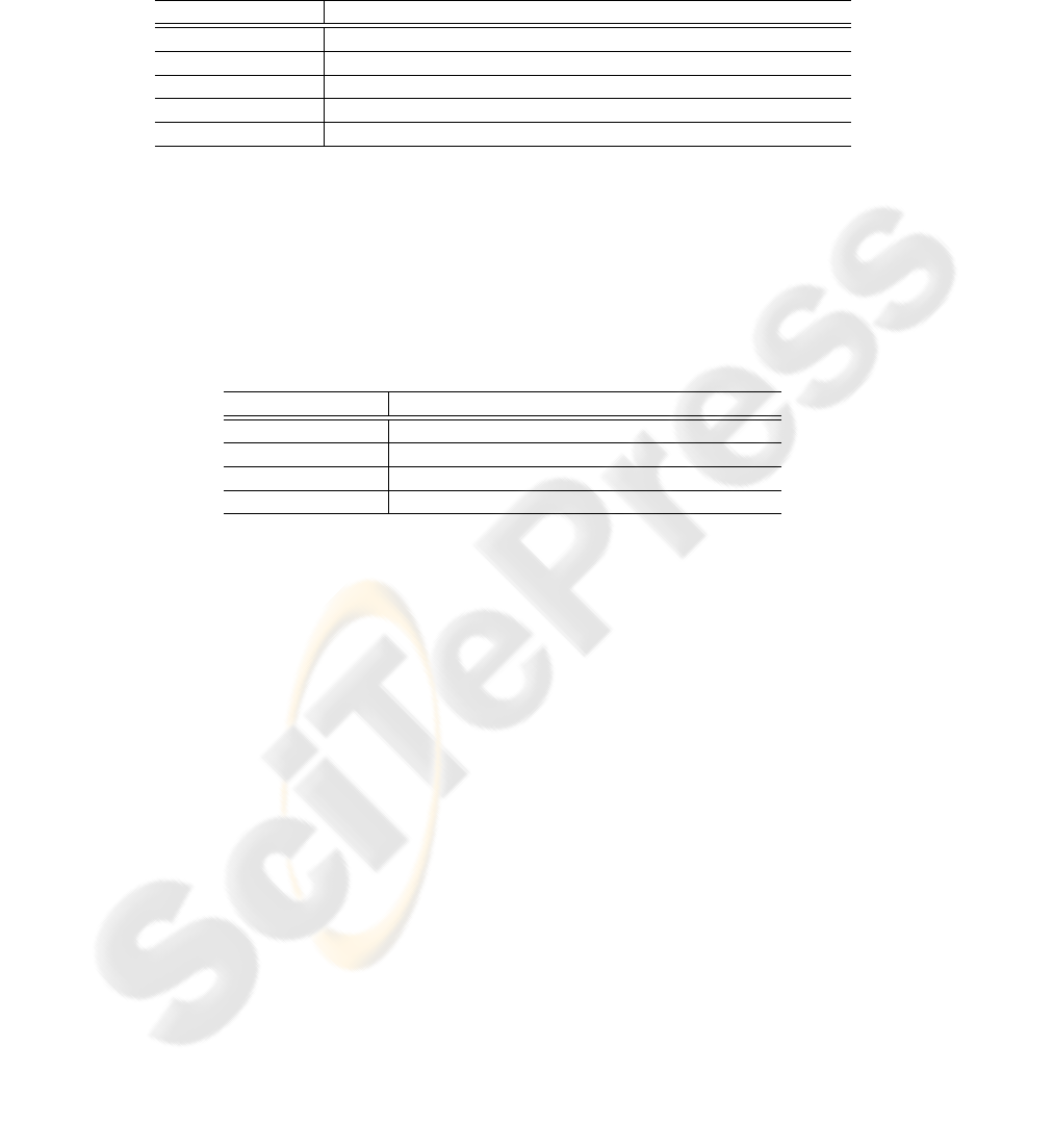
Table 1. GMPath terminal symbols
terminal symbol description
% comment line
∗ wildcard, placeholder for groups of nodes and edges
SystemN ode root node of the current GM, entry point of a query
HERE current start element, entry point of a query
(Edge−)Identifier (#) + alphanumerics + special characters for node and edge list names
Rules: Rules define the syntax of the grammar. A GMPathprogram is a sequence of
operations of arbitrary length, interpreted sequentially in order of their appearance.
<Program> ::= <operation> <Program>
GMPath differs between four different types of operations as shown in Tab. 2, which
are explained below. Any operation in GMPath is delimited by a \nl symbol.
Table 2. GMPath operations
operation description
commands switch between search only and manipulation mode
assignment node or edge list assignment to variable names
nodepathoperation path operation with a node list as result
edgepathoperation path operation with a edge list as result
<commands> ::= ’EnableCreateMode’ | ’EnableFindMode’
By default the FindMode is enabled. This means a query ending at non existing GM
elements (e.g. a node name was not found) returns an empty list or a list with the invalid
element respectively.
Enabling CreateMode causes the insertion of missing elements if addressed by a
query unambiguously (e.g. a node name at a distinct position in the GM hierarchy).
<assignment> ::= Identifier ’=’ <node path operation> |
ConIdentifier ’=’ <edge path operation>
This operation assigns the result list of node- or edge path operations to identifiers to
serve as substitutes. It is possible to embed identifiers in more complex operations to
concatenate queries.
<node path operation> ::=
<node path operation> {’/’,’//’,’\’,’\\’} <name> |
<node path operation> ’?(’ <path operation> ’)’ |
<edge path operation> {’>’,’<’,’ˆ’} <name> |
<name>
<edge path operation> ::=
<node path operation> {’>’,’<’,’ˆ’} <name> |
<edge path operation> ’?(’ <path operation> ’)’ |
<connection list name>
<path operation> ::= <node path operation> |
<edge path operation>
<name> ::= Identifier | ’
*
’ | ’SystemNode’ | ’HERE’
<connection list name> ::= ConIdentifier | ’HERE’
Node- and edge path operations are used to ’navigate’ through the GM, using
separators defining the logical direction (see also Fig. 4). On the one hand this can
be done by moving along the hierarchy structure upward or downward node by node.
On the other hand the GM elements are also accessible by navigating along the named-
and hyper edges, passing alternately from node to edge forward and backward.
In general a node- or edge path operation is a concatenation of node- and
edge names divided by separators, forming a path.
Table 3. GMPath separators
separator description
/ one step downward in hierarchy
//
all nodes below in hierarchy
\ one step upward in hierarchy
\\
all nodes above in hierarchy
> outgoing edge(s), forward connected node(s)
<
incoming edge(s), backward connected node(s)
∧ to and from hyper connected node
?(local query) intersection with local query
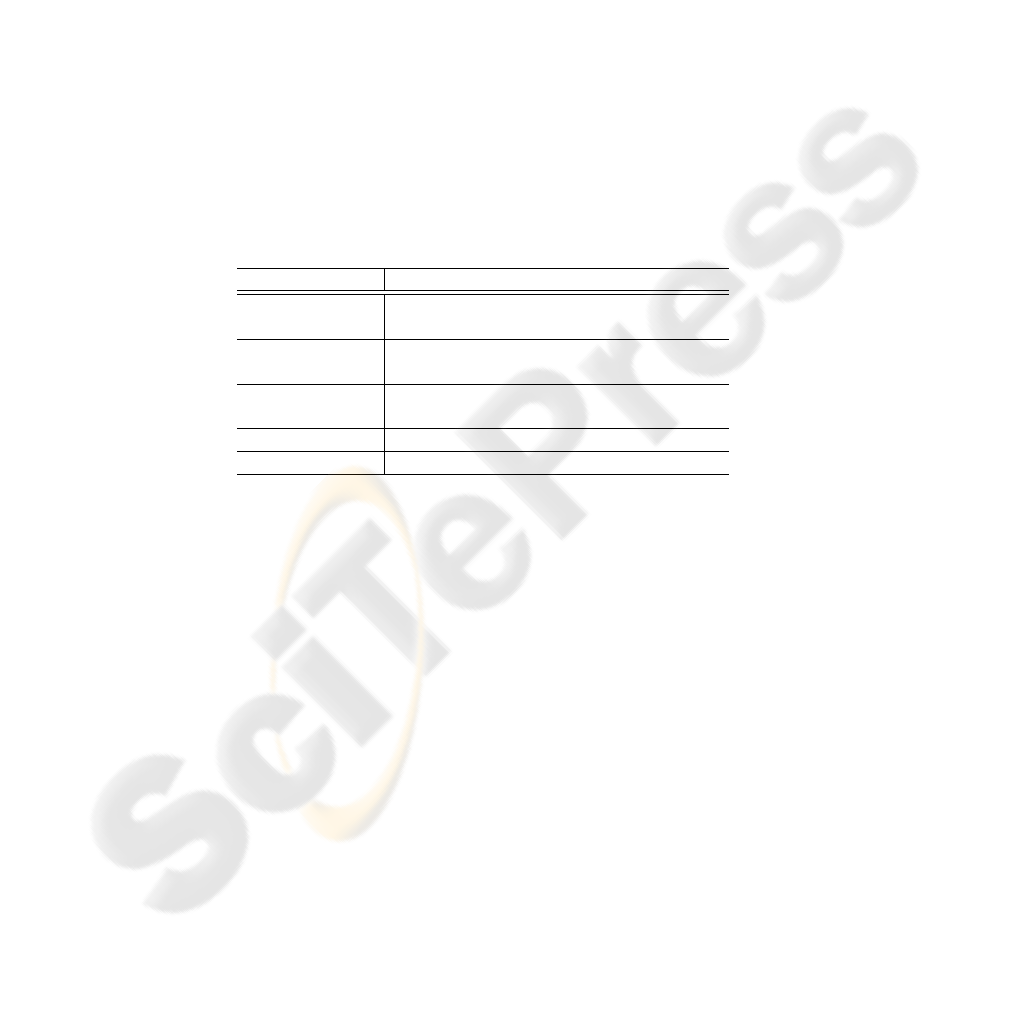
Separators The Separators are listed in Tab. 3. They are used to replace the current
list of nodes or edges by a list of adjacent GM elements filtered by the given name,
if not the wildcard symbol * is used alternatively. In other words the separators stand
for basic ’moves’ inside the GM as illustrated exemplary in Fig. 5. The intersection
’?(local query)’ processes an independent local query for every GM element as
start position in the current list. Forming a filter function at the current path position,
each GM element whose local query returns no result will be discarded.
Thus concatenating names of nodes and edges or wildcards with separators shapes
complex GM queries by readdressing iteratively adjacent GM elements (see also Fig.
4). To clarify the usage of GMPath paths, some more advanced examples are appended
in section 4.
4 Examples of GMPath Usage
Based on the GM in Fig. 6 a few example queries may ease the understanding of
GMPath and its application.
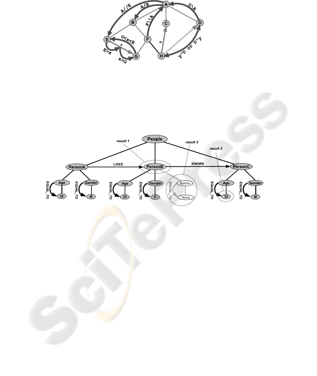
Fig.5. Examples of basics operations (separators) to navigate through a simplified GM
First a simple search query along the hierarchy and named edges is demonstrated,
followed by a filter query based using local requests. The third example shows how to
add new elements to the model.
Fig.6. Example GM for demonstrating GMPath queries
4.1 Query 1 - Searching and Assignment
LikedPeople = SystemNode/
*
>LIKES>
*
This query starts from the master node (SystemNode) and advances down hierarchically
one ’separator step’ (/), collecting all subjacent nodes from PersonA to PersonC due
to the wildcard symbol (*). Defined by the next separator (>), the outgoing edges of
all these three nodes are chosen. The following edge name LIKES selects only the edge
from the PersonA node. The last separator (>) finalized by the wildcard symbol returns
the target node of this edge regardless of the nodes name.
The resulting node list (PersonB) is stored to a variable named ”LikedPeople” for
later use.

4.2 Query 2 - Filtering
SystemNode/
*
?(HERE/Gender>EQUAL_TO>M)
?(HERE<KNOWS)/Age>EQUAL_TO>32
After collecting all person nodes two local queries (?(..)) are started. The first one
selects only these with the gender of ’M’ (PersonA, PersonC), the second one checks
for incoming KNOWS edges (PersonC). Afterwards the path steps down to the age of
the resulting persons.
The query returns with the age of all male persons, who are known by someone
(32).
4.3 Query 3 - Creating
EnableCreateMode
NameNode = SystemNode/PersonB/Name
NameValueNode = NameNode/Anna
NameNode > EQUAL_TO > NameValueNode
This example consists of more then one GMPath queries to create new GM elements,
where the new line symbol is not shown.
First the creation mode is set by the EnableCreateMode command. In the next two
lines new subjacent nodes (Name and Anna) are created below the PersonB node, ad-
dressed by their hierarchical locations. Assigned to two variable names (NameNode and
NameValueNode) both new nodes are stored. The forth GMPath query, using the previ-
ous stored nodes, i.e. navigating from one list to the other by advancing forward along
a not existing EQUAL
TO edge, creates the new connection and results in a structure as
shown in Fig. 6.
5 Conclusion
This paper introduced the newly developed query language GMPath. GMPath bases on
iterated basic localization steps through the logical environment of the current position,
providing searching, filtering, storing and manipulation functions to the user. Queries
start from every entry point of the model and can be build up dynamically by a program
through available API functions.
In the FACETS software framework GMPath is used to provide the user with an
universal interface to the internal graph models. Files containing GMPath commands
are parsed before and after the programmatic GM creation, mapping and configuration
process to allow modifications of parameters, of the model structure itself and the addi-
tion of user data. Furthermore GMPath forms an interface to graph models, which are
displayed, debugged and analyzed by external visualizing and analyzation applications,
allowing them to extract well-defined parts of the examined data model.
For the future we aim to expand the functionality of GMPath. We plan to imple-
ment set operations for the result lists, which are currently stored in variables (e.g.
set unions, intersections and difference sets). Further the inclusion of GMPath queries

stored as strings in the data model itself should make the handling of complex queries
more comfortable. Finally more options should be available to manipulate the GM (e.g.
renaming or deleting elements).
Acknowledgements: The research project FACETS is financed by the European Union
as Integrated Project (Nr. 15879) in the framework of the Information Society Tech-
nologies program.
References
1. Meier, K.: Fast Analog Computing with Emergent Transient States in Neural Architec-
tures. Integrated project proposal, FP6-2004-IST-FET. Proactive, Part B. Kirchhoff Institut
fr Physik, Ruprecht-Karls-Universit
¨
at, Heidelberg (2004)
2. Schemmel, J., Gr
¨
ubl, A., Meier, K., Mueller, E.: Implementing Synaptic Plasticity in a VLSI
Spiking Neural Network Model. Proceedings of the 2006 International Joint Conference on
Neural Networks IJCNN 2006, pp. 1–6, IEEE Press (2006)
3. Ehrlich, M., Mayr, C., Eisenreich, H., Henker, S., Srowig, A., Gr
¨
ubl, A., Schemmel, J.,
Sch
¨
uffny R.: Wafer-scale VLSI implementations of pulse coupled neural network. Interna-
tional Conference on Sensors, Circuits and Instrumentation Systems SSD’07, Hammamet-
Tunisia (2007)
4. Br
¨
uderle, D., Gr
¨
ubl, A., Meier, K., Mueller, E., Schemmel, J.: A Software Framework for
Tuning the Dynamics of Neuromorphic Silicon Towards Biology. Proceedings of the 2007
International Work-Conference on Artificial Neural Networks IWANN’07 Springer LNCS
4507, pp. 479–486, (2007)
5. Haeusler, S., Maass, W.: A Statistical Analysis of Information-Processing Properties of
Lamina-Specific Cortical Microcircuit Models. Cerebral Cortex 17(1), pp. 149-162, (2007)
6. Vieville, T., Kornprobst, P.: Modeling Cortical Maps with Feed-Backs - International Joint
Conference on Neural Networks (IJCNN), pp. 110-117 (2006)
7. Scholze, S., Ehrlich, M., Sch
¨
uffny, R.: Modellierung eines wafer-scale Systems fr pulsgekop-
pelte neuronale Netze - Proceedings of Dresdener Arbeitstagung Schaltungs- und Systemen-
twurf (DASS07), pp. 61–66 (2007)
8. Ehrlich, M., Wendt, K., Z
¨
uhl, L., Br
¨
uderle, D., Vogginger, B., M
¨
uller, E.: A software frame-
work for a wafer-scale neuromorphic hardware system, ANNIIP (2010), (submitted)
9. Wendt, K., Ehrlich, M., Mayr, C., Sch
¨
uffny, R.: Abbildung komplexer, pulsierender, neu-
ronaler Netzwerke auf spezielle Neuronale VLSI Hardware - Proceedings of Dresdener Ar-
beitstagung Schaltungs- und Systementwurf(DASS07) , pp. 127–132 (2007)
10. Wendt, K., Ehrlich, M., Sch
¨
uffny, R.: A graph theoretical approach for a multistep mapping
software for the FACETS project - Proceedings of the WSEAS CEA’08, pp. 189–194 (2008)
11. Diestel, R.: Graph Theory, Springer (2005)
12. Jordan, M.: Graphical Models. Computer Science Division and Department of Statistics.
University of California, Berkeley, California 94720-3860, USA (2004)
13. Berglund, A., Boag, S., Chamberlin, D., Fernandez, M., Kay, M., Robie, J., Simeon J., edi-
tors. XML Path Language (XPath) 2.0. W3C Working Draft 02, W3C (2003)
14. http://www.devincook.com/goldparser/. GOLD Parser System (2007)
