
A Software Framework for Mapping Neural Networks
to a Wafer-scale Neuromorphic Hardware System
Matthias Ehrlich
1
, Karsten Wendt
1
, Lukas Z¨uhl
1
, Ren´e Sch¨uffny
1
Daniel Br¨uderle
2
, Eric M¨uller
2
and Bernhard Vogginger
2
1
Technische Universit¨at Dresden, Lehrstuhl f¨ur Hochparallele VLSI-Systeme und
Neuromikroelektronik, 01062 Dresden, Germany
2
Ruprecht-Karls-Universit¨at Heidelberg, Kirchhoff-Institut f¨ur Physik
69120 Heidelberg, Germany
Abstract. In this contribution we will provide the reader with outcomes of the
development of a novel software framework for an unique wafer-scale neuromor-
phic hardware system. The hardware system is described in an abstract manner,
followed by its software framework which is in the focus of this paper. We then
introduce the benchmarks applied for process evaluation and provide examples
of the achieved results.
1 Introduction
Several current neuromorphic research projects, such as Fast Analog Computing with
Emergent Transient States – FACETS [1] or the Spiking Neural Network Simulator –
SpiNNaker [2], aim at the exploration of novel computational aspects of large scale,
biologically inspired neural networks with over a million neurons, simulated in real-
time or even with a speed-up in respect of the biological archetypes on full custom or
modified general purpose hardware.
The undertaken hardware research of FACETS encompasses the development of
a novel neuromorphic wafer-scale hardware system in an collaborative effort of the
Ruprecht-Karls-Universit
¨
at Heidelberg – UHEI and the Technische Universit
¨
at Dres-
den – TUD. The current level of development,Stage 2 incorporates the design of a wafer
element and its dedicated software framework for the mapping of neural architectures
onto the hardware substrate as well as the configuration and control of said system.
The wafer-scale hardware system is first described in section 1.1 followed by the
details of the software framework in section 2. The benchmarks applied are presented
in section 3 along with examples. An outlook concludes this contribution.
1.1 FACETS Stage 2 Architectural Overview
For the description of the FACETS Stage 2 hardware system as introduced by [1], [3]
and in the following referred to as FS2 hardware we will focus on details of the architec-
ture that influence the mapping of given neural networks onto the hardware. Figure 1 (a)
Ehrlich M., Wendt K., Z
¨
uhl L., Sch
¨
uffny R., Br
¨
uderle D., M
¨
uller E. and Vogginger B. (2010).
A Software Framework for Mapping Neural Networks to a Wafer-scale Neuromorphic Hardware System.
In Proceedings of the 6th International Workshop on Artificial Neural Networks and Intelligent Information Processing, pages 43-52
Copyright
c
SciTePress
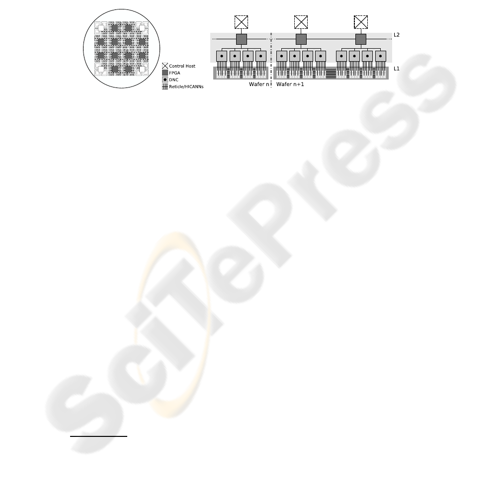
shows an abstract view of one wafer element of the FS2 hardware system. The foun-
dation layer of the FS2 hardware is an array of reticles shown as light gray squares,
housing High Input Count Analog Neural Network – HICANN or HC circuitry that was
developed at UHEI [1] and implements neural functionality such as neurons, synapses
and weight adaptation. On top resides a layer of communication circuits called Digital
Network Chip – DNC developed at TUD [3]. The third and topmost layer represents
a regular grid of FPGAs
3
, colored dark gray. Disabled or inoperable components are
colored white.
(a) (b)
Fig.1. Abstract view of a) one wafer from top and b) the communication hierarchy from side.
Figure 1 (b) depicts the communication networks, their hierarchy and connectivity.
Two distinct communication networks can be distinguished. An asynchronous, address
coded, named Layer 1 – L1 utilized by HCs at wafer level for intra-wafer communi-
cation and a second one, named Layer 2 – L2 utilized by DNCs and FPGAs for syn-
chronous, packet based inter-wafer communication. Host computers are connected via
Ethernet to the FPGAs to handle the mapping, configuration and control process de-
scribed in the following.
1.2 The HICANN
A simplified view of the HC chip following [1], [4] is drawn in figure 2 as a symmetric
array of neural and communication elements. The dendritic membranes, or denmems
are the neural core components. Each denmem provides two synaptic input circuits
emulating ion channels. Up to 2
6
denmems can be grouped, i.e. connected together to
form a neuron with a higher synaptic input count or a more detailed model by increasing
the number of conductive time constants. Synapses, situated in an adjacent synapse
array are connected to the denmems. Whether a synapse is connected to the excitatory
or inhibitory input of a denmem is decided row-wise in the synapse driver, or syndriver.
A syndriver is fed from one of 2 × 2
7
vertical L1 bus lanes via select-switches or from
a neighboring syndriver. It drives the synapses via strobe lines, as depicted as thin lines
in figure 2 lens (1), and selects the receiving synapse via an address, the thick lines.
A fixed part of the synapses address determines the strobe line to use and follows the
address pattern shown in lens (2). Each synapse belongs to the denmem located below
the synapse array in the same column. A group of denmems is connected to one of 2
6
3
Field Programmable Gate Array
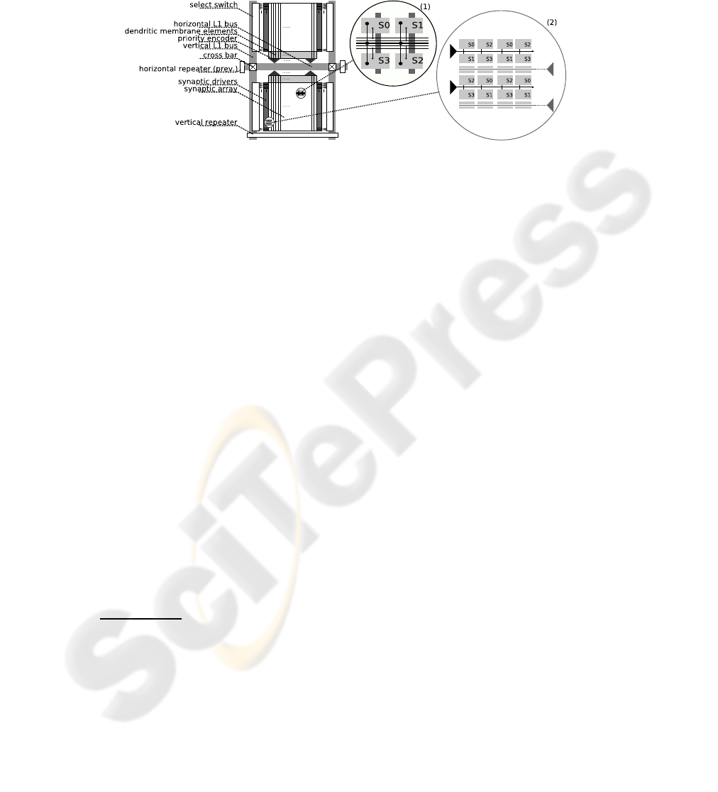
horizontal L1 bus lanes and L2 by a priority-encoder that multiplexes and prioritizes
the bus access.
Fig.2. A schematic view of one HICANN [1], [4].
Repeaters and cross-bars are then configured to interconnect the vertical and hori-
zontal buses with unidirectional connections. The neural pulses generated by the den-
mems are transmitted asynchronously on L1 as bit sequence encoding the senders ad-
dress or arbitrarily on L2 encoding the address and the pulse timing.
1.3 Parameter Space
Every denmem implements the dynamics of the Adaptive Exponential Integrate-and-
Fire – AdEx model [5] including model’s mechanisms such as spike frequency adaption
and active spike generation. A total of 24 parameters determine the behavior of a den-
mem, some of which correspond directly to the AdEx model, others are of technical
nature
4
.
The synaptic weight of a synapse is determined by an individual digital weight
value of 4-bit resolution and a fixed maximum conductance g
max
, which can be set for
every synapse row by a programmable analog parameter. The synapse circuit generates
a square current pulse, which is injected into one of the synaptic input circuits of the
denmem, where it modulates a transient synaptic conductance. The amplitude of this
square current pulse is weight × g
max
and its length is τ
STDF
, where τ
STDF
is modulated
by the short term depression or facilitation – STDF [6] plasticity mechanism in the
synapse driver.
We assume a hardware model setup for configuration of the FS2 hardware follow-
ing [1], [4]. With an 8×8 HCreticle array of 8 HCs per reticle and 48 functioning reticles
per wafer, thus a total of 512 HCs. Furthermore, 8 HCs per DNC result in 48 DNCs and
4 DNCs per FPGA give a total of 12 FPGAs. With N
MaxHC
∈
2
3
, 2
4
, ..., 2
8
5
a
4
As configurable parameters allow to vary time constants of neural and synaptic dynamics it is
possible to operate the FS2 hardware system with a speed-up from 10
3
to 10
5
compared to
biological scale, depending on the system’s load, as excessive speed-up may lead to pulse loss
due to limited bandwidth.
5
N
MaxHC
is held constant for a network and determined by the detail level of the neuron
model [1] or the synaptic input count of a neuron [4].
maximum neurons per HC the total number of available neurons is given by N
HW
=
H × N
MaxHC
, where H denotes the number of HCs available for mapping
6
. The num-
ber of synapses available on the hardware S
HW
= H × S
HC
, with S
HC
being number
of synapses per HC, which for the used configuration is constant with: 2 × 25 6
2
and the
number of dendritic elements per HC D which equals 2 × 256. With 2
6
denmems per
priority encoder this results in 8 priority encoders and thus a 6-bit L1 address.
2 The FACETS Stage 2 Software Framework
The FS2 software framework provides the functionality to map a given network onto
the hardware, configure it, control the simulation and examine the results of the map-
ping and simulation process.
2.1 PyNN & Hardware Abstraction Layer
For the FACETS hardware systems, a user interface is now available that provides a
novel way to bridge the gap between the domains of pure software simulators and neu-
romorphic hardware devices [7], [8]. The Python-based neural network modeling lan-
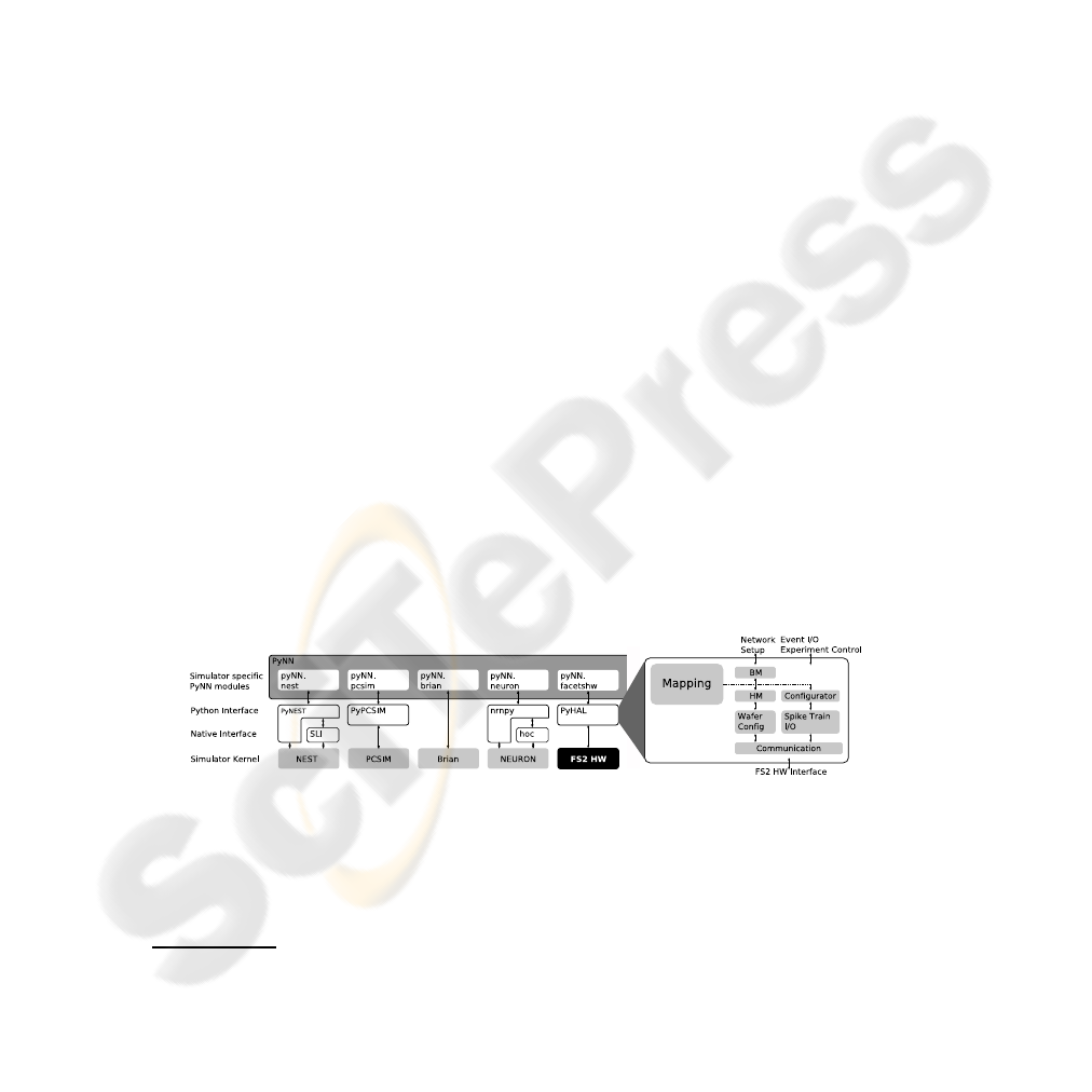
guage PyNN [9], see Figure 3 has been developed by FACETS members. It represents
a simulator-independent set of functions, classes and standards for units and random
number generation that can be used to describe complex models of networks of spiking
neuronsusing a biological terminology - either in an interactive or in a scripting fashion.
Models written with the PyNN API can be executed with various established software
simulation tools such as NEURON [10], NEST [11], Brian [12] or PCSIM [13]. For all
supported back-ends a specific Python module automatically translates the PyNN code
into the native scripting language of the individual simulator and re-translates the re-
sulting output into the domain of PyNN. Thus, PyNN allows to easily port experiments
between all supported simulators and to directly and quantitatively compare the results.
Among many other benefits, this unification approach can increase the reproducibility
of experiments and decreases code redundancy.
Fig.3. PyNN framework following [9] and the FS2 HAL.
The integration of the FACETS hardware systems into the PyNN concept adopts
these benefits. Additionally,the PyNN hardwaremodule offers a transparent method via
which the communities of computational neuroscience and neuromorphic engineering
6
H is not necessarily equal to the total number of HCs available in the system.

can exchange experiments and results. With the novel approach, non-hardware-experts
can be provided with a well documented interface that is very similar to interfaces of
most established software simulators [14].
While PyNN itself represents a precise definition of the user interface, the Hardware
Abstraction Layer – HAL module actually implements the automated translation of any
given network setup into the data model described in the following, which performs the
mapping of the experiment onto the available hardware resources and into the hardware
parameter domain. The said translation process also conducts the transition between the
Python domain of PyNN and the C++ objects of the mapping framework and all lower
software layers.
2.2 Data Model
To cope with the hierarchical structure of the hardware system a data model resembling
a hierarchical hyper graph was developed [15]. The graph model consists of vertices
representing data objects and edges as relationships among them. Where a vertex holds
atomic data, an edge can be a hierarchical, a named or a hyper edge. Hierarchical
edges model a parent-child relationship, thus structuring the model. Named edges form
a directed and named relation between two vertices from/to any location in the model
and hyper edges assign a vertex to a named edge, characterizing it in more detail. Its
flexibility allows to store every information during the configuration process, i.e. the
models itself as well as the placement, routing and parameter transformation data.
2.3 Data Interface
To overcome the access of nodes and edges or subsets of the graphs elements by navi-
gating the native data structure we provide a novel path-based query-language, named
GMPath. Via GMPath, along with its corresponding API as described in the accompa-
nying publication [16] data can be retrieved from or stored to the models by a program
via static or dynamically created queries.
2.4 The Mapping Process
With regard to topology constraints between hardware blocks such as connectivity, con-
nection counts, priorities and distances as well as source/target counts the mapping
determines a network configuration and parameter set for the hardware. This is accom-
plished in the three steps of placement, routing and parameter transformation.
During placement, the mapping process assigns neural elements like neurons or
synapses to distinct hardware elements. As placement comprises different optimiza-
tion objectives, it can be characterized as a multi-criteria problem the solution quality
of which influences the overall mapping results significantly. Possible objectives are,
e.g. to minimize the neural input/output variability clusterwise, to minimize the neural
connection count, also clusterwise, or to minimize routing distances while maintaining
compliance with constraints such as parameter limitations or hardware element capac-
ities. As the optimization problem is NP-complete a force-based optimization heuristic

with user-defined weightings, named NFC, was developed to achieve these objectives in
acceptable computation time. This algorithm balances ”forces”, the implementation of
said optimization objectives in an n-dimensional space until an equilibrium is reached.
In a subsequent separation step it assigns its data objects to clusters with affine proper-
ties. We distinguish between the simple algorithms described in [17] and the NFC.
The routing subsequently determines a configuration for the synaptic connections
on L1 and L2 and can be split into the two subsequent steps of intra- and inter-wafer
routing. The intra-wafer routing algorithms [4] route connectivity exclusively on L1
and reserve L2 for inter-wafer routing which is inactive for a wafer-scale system.
Parameter transformation finally maps the model parameters of given neurons and
synapses, such as weights, types or thresholds into hardware parameter space. As not
every biological parameter, or its corresponding model parameter in the PyNN descrip-
tion, has its individual counterpart in hardware but is often emulated by a set of correlat-
ing parameters, an adequate biology-to-hardware parameter translation has to be found,
e.g for the membrane circuits a transformation from 18 biological parameters of the
PyNN AdEx neuron model description into a configuration of 24 adjustable electrical
hardware parameters.
The desired speedup factor between 10
3
to 10
5
which is determined by the temporal
dynamics of the membrane and synaptic circuitry is finally set by adjusting parameters
as the size of the membrane capacitances, conductances responsible for charging it or
the current controlling the synaptic conductance.
2.5 Analysis
A new standalone application named Graph Visualization Tool – GraViTo aids the user
with the analysis and debugging of mapping data. GraViTo incorporates envisioNN
and H3 graph viewer [18] modules that display graph models in textual and graphical
form and gathers statistical data. One can selectively access single nodes inside the data
structure and visualize its context, dependency and relations with other nodes in the
system.
Views of GraViTo are shown in figure 4, such as the tree view to browse the hierar-
chical structure of the graph model, the GMPath query view and the 3D view. The 3D
view is specialized on rendering BM and HM and the mapping between them in three
dimensional form to provide a contextual view over the models, their components and
connectivity. It also provides a global overview over the hardware components and the
networks. To support the analysis of the mapping results various statistics are gathered
and displayed, e.g. as histograms for utilization of the crossbars, the HC blocks or the
synaptic connection lengths.
3 Benchmarks
Benchmarks aid in evaluating the mapping process. First benchmarks concerning map-
ping efficiency with focus on intra-wafer routing and hardware utilization were car-
ried out at UHEI [4] with random networks, macrocolumns and locally dense/globally
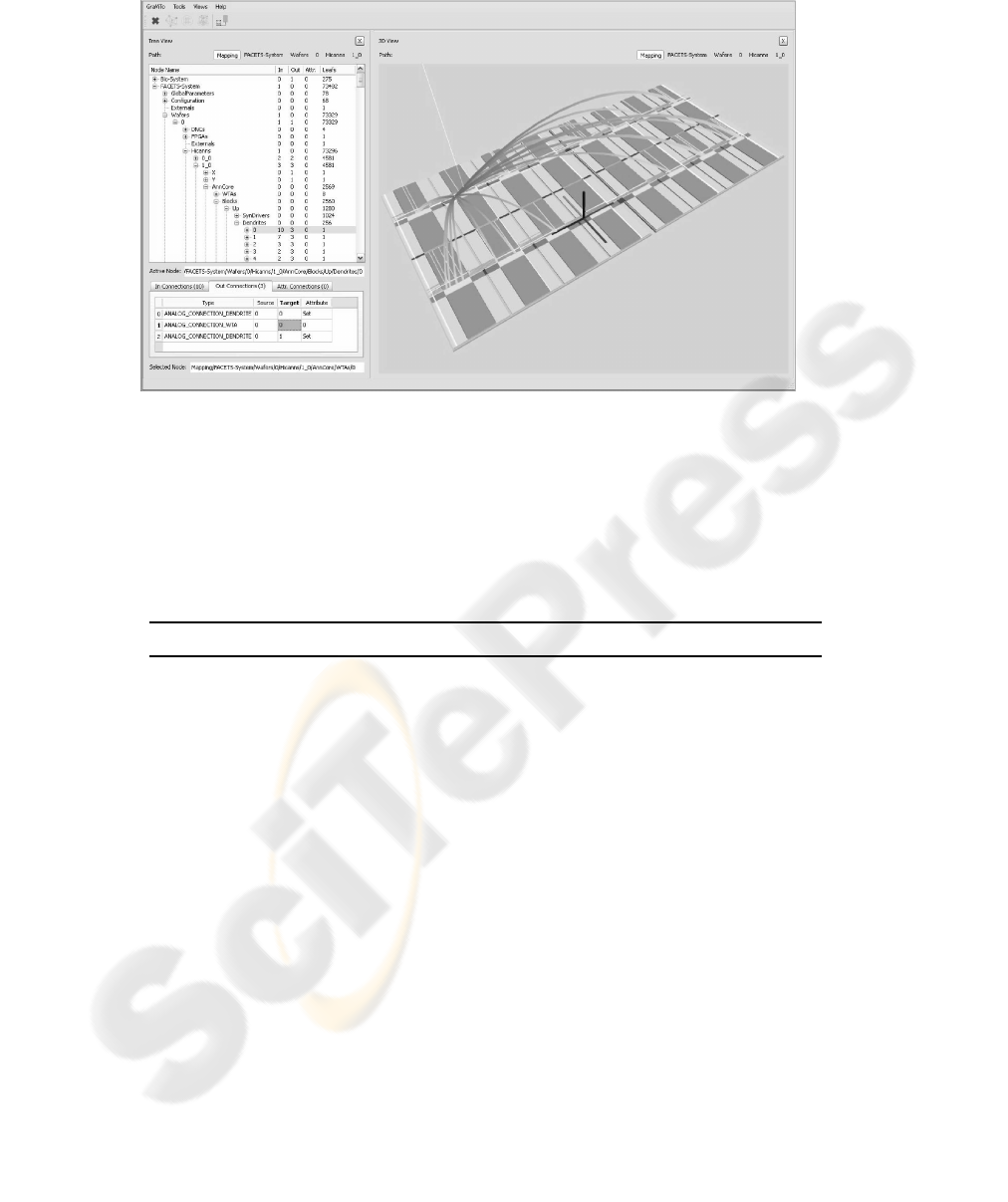
Fig.4. Screenshot of GraViTo’s viewers.
sparse connected networks in order to explore the system’s design space. New bench-
marks are listed in table 1. The new benchmarks are implemented in PyNN and were
provided from FACETS project partners but also from the neuromorphic research com-
munity outside of FACETS.
Table 1. Selected Benchmarks.
Benchmark Description
INCM ALUF Synfire Chain based on [19], provided by
L’Institut de Neurosciences Cognitives de la M´eediterran´ee
– INCM, Marseille, France in cooperation with
Albert-Ludwigs-Universit¨at Freiburg – ALUF, Freiburg, Germany
KTH Layer 2/3 Attractor Memory following [20], provided by
Kungliga Tekniska H¨ogskolan - KTH, Stockholm, Sweden
UNIC Model of Self-Sustained AI States following [21], provided by the
Integrative and Computational Neuroscience Unit – UNIC of the
Centre national de la recherche scientifique – CNRS, Gif-sur-Yvette, France
As an example we apply the mappingprocess to the scaled benchmarksin a 4×4 ret-
icle configurationwith an N
MaxHC
= 2
6
to evaluatethe mapping quality. As a measure
of the overall mappingquality the parameters as defined in [4] apply. The routing quality
q
Route
= S
Map
/S
BIO
, with S
Map
being the number of mapped synapses over S
BIO
,
which is the number of synapses in the BM. Thus, (1 − q
Route
) is the relative synapse
loss. The hardware efficiency is described by e
HW
= S
Map
/S
HW
, where S
HW
de-
notes the synapses available on the FS2 hardware for mapping. As a further parameter
for network classification we define the connection density ρ
Syn
= S
BIO
/N
2
BIO
.

(a) (b) (c)
Fig.5. Connection matrices of the (a) INCM, (b) KTH and (c) UNIC networks.
Connection matrices for networks of 10
3
neurons as shown in figure 5 illustrate the
benchmarks synaptic connectivity types. Darker areas represent groups of neurons with
an ρ
Syn
above average.
As stated in [2] the worst scenario are randomly connected networks with a constant
ρ
Syn
due to their absent locality. In case of avg. S
BIO
above the configured HW limit
one may reduce the neurons per HC, provide more synapses and thus improve q
Route
at the expense of less e
HW
, but an expanded distribution of neurons and thus longer
connections may consume even more routing resources in turn at a certain point again
reducing q
Route
.
The ρ
Syn
of the benchmarks however decrease with approx. 1/x, see 6 (a) leading
to an almost constant or only slightly increasing average synaptic input count. Never-
theless the mapping results for networks with N
BIO
above 10
5
show a clear decrease in
q
Route
by exceeding 15% compared to fully routed which may be caused by intra-wafer
routing resources utilized to capacity, invigorated by an observation of the steepest de-
cline in q
Route
for UNIC, the network with the lowest avg. ρ
Syn
.
Tests also showed that the NFCalgorithm can minimize the routing losses compared
to the simple algorithms up to 20% for networks with a higher locality, such as the
INCM, the more efficient the larger the network.
0
0.01
0.02
0.03
0.04
0.05
0.06
0.07
0.08
0.09
10
3
10
4
connection density [%]
#Neurons
INCM
KTH
UNIC
(a)
0
100
200
300
400
500
600
700
800
10
3
10
4
Model Size [MByte]
#Neurons
INCM
KTH
UNIC
(b)
0
100
200
300
400
500
600
0
10
4
NFC runtimes [min]
#Neurons
INCM
KTH
UNIC
(c)
Fig.6. Networks avg. ρ
Syn
(a), BM size (b) and NFC algorithm runtime (c).
As a second major requirement for the usability of the FS2 hardware simulator
platform a fast configuration and reprogramming is inevitable so we use the scaling test
also to determine the software process’ scalability in terms of time and space.
Figure 6 (b) shows that the BMgraph grows almost linearly depending on the number
of neurons and the synaptic density. So for the given benchmarks the model sizes for

networks with a neuron count of N
BIO
≤ 10
5
and an approximate average ρ
Syn
≤
10% stay within a acceptable limt of 10GB. The simpler algorithms runtime scales with
O(n) and remains within an upper bound of approximately 3 hours whereas the NFC
algorithms, in spite of the cubical problem, grows below O(n
2
), as can bee seen in 6 (c)
fulfilling the requirement of a resonable runtime for complex mapping problems.
Test where carried out under Red Hat 4.1.2 running on an AMD Opteron
TM
875
Dual Core CPU @2.2GHz quad processor system with 32GByte of RAM.
4 Conclusions
Although the FS2 hardware system is on a higher level of abstraction similar to other
reconfigurable hardware architectures it is unique in both its functionality and the sys-
tems dimension. So new algorithms and heuristics are necessary that take into account
the peculiarities of such a system. We presented outcomes and benchmark examples of
the complete FS2 software framework which seamlessly integrates the FS2 hardware
system into PyNN.
As shown by the benchmarks, a mapping is found in a reasonable time, however, the
networks structure of larger networks is modified by the software process and through
hardware resource limitations. To examine the impact of these losses on the networks
behavior comparative simulations with pre- and post- mapping netlists are carried out
on simulators introduced in section 3. As a further consequence we consider the incor-
poration of L2 into intra-wafer communication as essential as it will alleviate the L1
losses. Iterative optimization of the mapping results will then trade-off between simula-
tion speedup, hardware efficiency and routing quality by adjusting the software process
parameters.
An in depth evaluation of the benchmark results will follow with the upcoming
publication of the NFC algorithm.
Acknowledgements
The research is financed by the European Union in the framework of the Information
Society Technologies program, project FACETS (Nr. 15879). Furthermore, we would
like to thank Jens Kremkow of ALUF, Pradeep Krishnamurthy of KTH and Andrew
Davison of CNRS for making the PyNN scripts available to us.
References
1. Schemmel, J., Fieres, J., Meier, K.: Wafer-scale integration of analog neural networks. In:
Proceedings IJCNN2008, IEEE Press. (2008) 431–438.
2. Khan, M., Lester, D., Plana, L., Rast, A., X.Jin, Painkras, E., Furber, S.: SpiNNaker: Map-
ping Neural Networks onto a Massively-Parallel Chip Multiprocessor. In: Proceedings 2008
International Joint Conference on Neural Networks, IJCNN 2008. (2008) 2849 – 2856.
3. Ehrlich, M., Mayr, C., Eisenreich, H., Henker, S., Srowig, A., Gruebl, A., Schemmel, J.,
Schueffny, R.: Wafer-scale VLSI implementations of pulse coupled neural networks. In:
International Conference on Sensors, Circuits and Instrumentation Systems SSD’07. (2007)

4. Fieres, J., Schemmel, J., Meier, K.: Realizing Biological Spiking Network Models in a
Configurable Wafer-Scale Hardware System. In: IEEE International Joint Conference on
Neural Networks IJCNN. (2008) 969 – 976.
5. Brette, R., Gerstner, W.: Adaptive Exponential Integrate-and-Fire Model as an Effective
Description of Neuronal Activity. Journal of Neurophysiology 94 (2005) 3637–3642
6. Schemmel, J., Br¨uderle, D., Meier, K., Ostendorf, B.: Modeling Synaptic Plasticity within
Networks of Highly Accelerated I&F neurons. In: Proceedings of the 2007 IEEE Interna-
tional Symposium on Circuits and Systems (ISCAS’07), IEEE Press (2007)
7. Br¨uderle, D., M¨uller, E., Davison, A., Muller, E., Schemmel, J., Meier, K.: Establishing
a Novel Modeling Tool: A Python-based Interface for a Neuromorphic Hardware System.
Front. Neuroinform. 3 (2009)
8. Davison, A., Muller, E., Br¨uderle, D., Kremkow, J.: A common language for neuronal net-
works in software and hardware. The Neuromorphic Engineer (2010)
9. Davison, A. P., Br¨uderle, D., Eppler, J., Kremkow, J., Muller, E., Pecevski, D., Perrinet, L.,
Yger, P.: PyNN: a common interface for neuronal network simulators. Front. Neuroinform.
2 (11) (2009) 1 – 10
10. Hines, M. L., Carnevale, N. T.: The NEURON Book. Cambridge University Press, Cam-
bridge, U.K. (2006)
11. Gewaltig, M. O., Diesmann, M.: NEST (NEural Simulation Tool). Scholarpedia 2 (2007)
1430
12. Goodman, D., Brette, R.: Brian: a simulator for spiking neural networks in Python. Front.
Neuroinform. 2 (2008)
13. Pecevski, D. A., Natschl¨ager, T., Schuch, K. N.: PCSIM: A Parallel Simulation Environment
for Neural Circuits Fully Integrated with Python. Front. Neuroinform. 3 (2009)
14. Br¨uderle, D., Bill, J., Kaplan, B., Kremkow, J., Meier, K., M¨uller, E., Schemmel, J.:
Simulator-Like Exploration of Cortical Network Architectures with a Mixed-Signal VLSI
System. In: Proceedings of the 2010 IEEE International Symposium on Circuits and Sys-
tems (ISCAS’10). (2010) Accepted
15. Wendt, K., Ehrlich, M., Sch¨uffny, R.: Graph theoretical approach for a multistep mapping
software for the FACETS project. In: 2nd WSEAS Int. Conference on Computer Engineering
and Applications (CEA’08). (2008)
16. Wendt, K., Ehrlich, M., Sch¨uffny, R.: GMPath - A Path Language for Navigation, Infor-
mation query and modification of data graphs. In: 6th International Workshop on Artificial
Neural Networks and Intelligent Information Processing (ANNIIP). (2010) Accepted
17. Wendt, K., Ehrlich, M., Mayr, C., Schffny, R.: Abbildung komplexer, pulsierender,
neuronaler Netzwerke auf spezielle neuronale VLSI Hardware. Dresdner Arbeitstagung
Schaltungs- und Systementwurf DASS 2007 (2007) pp. 127–132
18. Munzner, T.: H3: Laying out large directed graphs in 3d hyperbolic space. In: Proceedings
of the 1997 IEEE Symposium on Information Visualization. (1997) 2–10
19. Kremkow, J., Perrinet, L., Aertsen, A., Masson, G.: Functional consequences of correlated
excitatory and inhibitory conductances. (2009) Submitted
20. Lundqvist, M., Rehn, M., Djurfeldt, M., Lansner, A.: Attractor dynamics in a modular net-
work of neocortex. Network:Computation in Neural Systems 17:3 (2006) 253–276
21. Destexhe, A.: Self-sustained asynchronous irregular states and Up/Down states in thala-
mic, cortical and thalamocortical networks of nonlinear integrate-and-fire neurons. Journal
of Computational Neuroscience 3 (2009)
