
Maximization of the Operating Volume using HF RFID
Loop Antennas
Kevin D’hoe
1
, Nobby Stevens
1
, Jean-Pierre Goemaere
1
, Lieven De Strycker
1
and Bart Nauwelaers
2
1
DraMCo research group, Catholic University College Ghent, Association K. U. Leuven
Gebroeders Desmetstraat 1, 9000 Ghent, Belgium
2
Department of Electrical Engineering, ESAT, K. U. Leuven
Kasteelpark Arenberg 10, 3001 Leuven, Belgium
Abstract. This article describes how a passive radio frequency identification
(RFID) system is optimized. Our attention focuses on the operating volume of a
circular loop antenna. Hereby the design of loop antennas is given a new approach
to establish a maximum operating volume. Therefore, the off-axis magnetic field
is investigated. This is done for a circular loop in free space and in the vicinity
of a metal plane. A numerical approach is given towards the maximization of the
operating volume. The goal is to provide new insights into the design of a loop
antenna and enhance the reliability of the RFID system.
1 Introduction
Within the domain of industrial applications, Radio Frequency Identification (RFID)
has become a popular technology. Particularly when it comes to tracking and tracing
of objects, passive RFID technologies have been found to provide a suitable solution.
This technology is based on the principle of inductive coupling between two loop an-
tennas, namely a reader loop antenna and a transponder loop antenna. Although this
technology is well known, many problems occur when it is used in industrial environ-
ments. The presence of metals in the vicinity of the RFID loop antenna often causes
readout reliability issues. For this reason, the design of the reader loop antenna should
be optimal to achieve a maximum volume where a transponder is detected. This vol-
ume is called the operating volume. The research is based on previous work where the
optimal diameter [1] of a circular loop antenna was examined for ideal and non-ideal
conditions, e.g., the presence of a conducting plate in the vicinity of a loop antenna. In
that work [1], the magnetic field at the symmetry axis of a circular loop antenna is con-
sidered. Within this paper, we will focus on the investigation of the off-axis magnetic
field which will finally lead to new insights towards the design of a loop antenna. Two
specific cases were handled, namely a loop antenna in free space and a loop antenna
near a conducting plate. We will discuss how the operating volume is maximized and
which parameters should be taken into account. This approach will lead to the design
of reliable RFID systems.
D’hoe K., Stevens N., Goemaere J., De Strycker L. and Nauwelaers B.
Maximization of the Operating Volume using HF RFID Loop Antennas.
DOI: 10.5220/0003026000230029
In Proceedings of the 4th International Workshop on RFID Technology - Concepts, Applications, Challenges (ICEIS 2010), page
ISBN: 978-989-8425-11-9
Copyright
c
2010 by SCITEPRESS – Science and Technology Publications, Lda. All rights reserved

2 The Off-axis Magnetic Field in Free Space
We consider a quasi-static approach, thus with a constant current distribution over the
entire loop antenna. This is plausible for loop antennas whose circumference is much
smaller then the wavelength of the applied signal. This implies that the radius r
l
can
not increase unlimited. We will consider loop antennas with a radius up to r
l
= 0.6 m,
which certainly holds the predetermined condition for LF and HF RFID systems.
For lower frequencies, the Biot-Savart law (1) may be applied for the calculation of the
magnetic field caused by a current in the loop antenna. A differential magnetic field
strength, dH, results from a differential current element I dl, Fig. 1. The total magnetic
field H(r) can be written as in equation (2), where L
w
is the total length of the loop
antenna.
dH(r, r
0
) =
µ
0
4π
I
dl(r
0
) × (r − r
0
)
|r − r
0
|
3
(1)
Fig. 1. Circular loop antenna in free space.
H(r) =
µ
0
4π
I
Z
L
w
dl(r
0
) × (r − r
0
)
|r − r
0
|
3
(2)
Due to symmetry reasons, one can see that knowledge of the magnetic field in the
yz-plane is sufficient to know the magnetic field at any other place. After some math-
ematical manipulations, we obtained the following components of the magnetic field
as in equations (3), (4) and (5) in the yz-plane. A mixture of cylindrical and Cartesian
coordinates has been applied to handle the configuration of Fig. 1 [2]. The radius of the
loop antenna is called r
l
.
H
x
(y, z) =
Ir
l
z
4π
Z
2π
0
cos φ
0
dφ
0
(r
2
l
+ y
2
− 2r
l
y sin φ
0
+ z
2
)
3/2
(3)
H
y
(y, z) =
Ir
l
z
4π
Z
2π
0
sin φ
0
dφ
0
(r
2
l
+ y
2
− 2r
l
y sin φ
0
+ z
2
)
3/2
(4)
17
H
z
(y, z) =
Ir
l
4π
Z
2π
0
(r
l
− y sin φ
0
) dφ
0
(r
2
l
+ y
2
− 2r
l
y sin φ
0
+ z
2
)
3/2
(5)
After numerical calculation of H
x
(y, z) (3), this component seems to be zero for all
values of y and z.
These integrals cannot be solved analytically. For this reason, we have evaluated these
integrals by use of standard numerical integration methods.
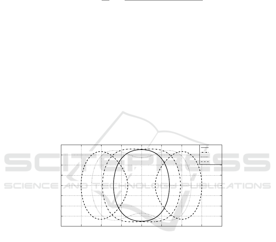
3 Operating Volume in Free Space
The minimum operating field H
min
of a transponder is defined by the ISO 15693 [3–5]
and has a value of 150 mA/m. It is clear that a reader should generate a field of at least
H
min
to activate a transponder. The volume that is delineated by the 150 mA/m-contour
of the total magnetic field H
tot
is called the operating volume. In Fig. 2, the operating
volume is presented for different values of r
l
. By considering H
tot
, we assume that the
transponder is always oriented perpendicular to the field lines. We have chosen the cur-
rent I equal to 0.14 A (which corresponds to a power level of 1 W in a 50 Ω impedance
reference system).
−0.8 −0.6 −0.4 −0.2 0 0.2 0.4 0.6 0.8
−0.2
−0.15
−0.1
−0.05
0
0.05
0.1
0.15
0.2
y [m]
z [m]
r
l
= 0.2 m
r
l
= 0.3 m
r
l
= 0.4 m
r
l
= 0.5 m
Fig. 2. Operating volume delineated by the H
min
of a loop antenna.
Considering Fig. 2, one can see that the operating volume is increased as r
l
expands
within a certain domain. Where r
l
is chosen equal to 0.4 m we find the largest operating
volume. A disadvantage is the reduction of the magnetic field on the axis of symme-
try (y = 0). For r
l
= 0.5 m, we can see two separated contour lines which means that
a transponder fails to detect in the middle of the loop antenna. It is clear that this is
preferably avoided.
In Fig. 3 the operating volume is calculated in function of r
l
for different values of
I. For each specific current I through the loop antenna there exists a radius r
l
where the
18
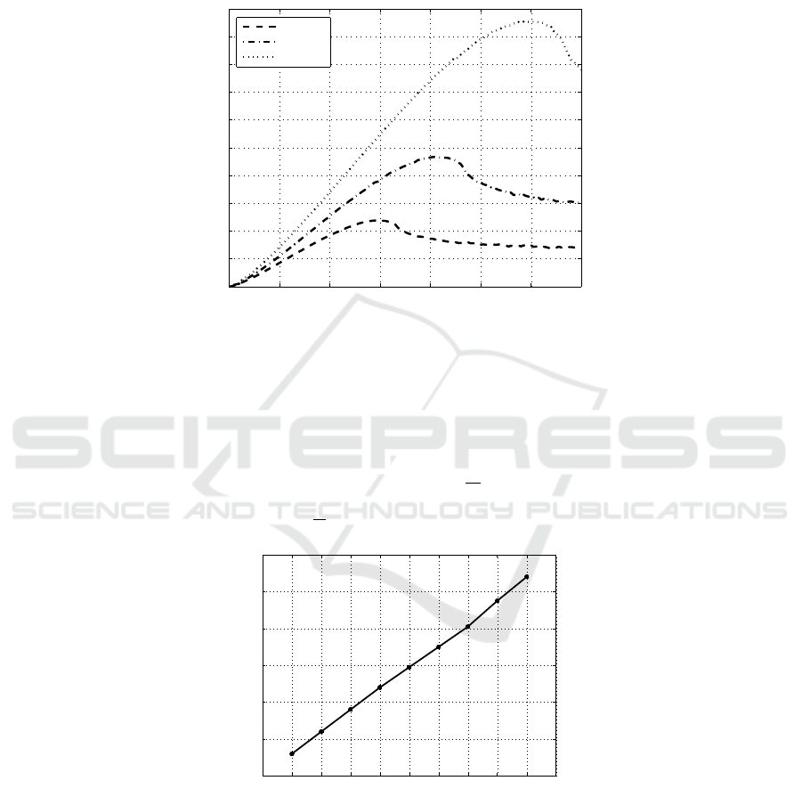
operating volume is maximized. Considering I = 0.14 A, it is found that the maximum
operating volume is provided at a radius r
l
of 0.405 m. For values which our higher then
r
l
= 0.405 m we see a strong decrease of the operating volume which then stabilizes.
0 0.1 0.2 0.3 0.4 0.5 0.6 0.7
0
0.2
0.4
0.6
0.8
1
1.2
1.4
1.6
1.8
2
Operating volume [m
3
]
r
l
[m]
I = 0.1 A
I = 0.14 A
I = 0.2 A
Fig. 3. The operating volume for different values of I .
Fig. 4 gives the optimal radius r
l
providing a maximum operating volume for a
specific current I through the circular loop antenna. We have found that there is a lin-
ear correspondence between the current I and the radius r
l
that provides a maximum
operating volume:
r
l
= αI ([α] =
m
A
). (6)
The value of α is found to be 3
m
A
.
0 0.02 0.04 0.06 0.08 0.1 0.12 0.14 0.16 0.18 0.2
0
0.1
0.2
0.3
0.4
0.5
0.6
I [A]
r
l
[m]
Fig. 4. The optimal radius r
l
for a specific current I which provides a maximum operating vol-
ume.
19
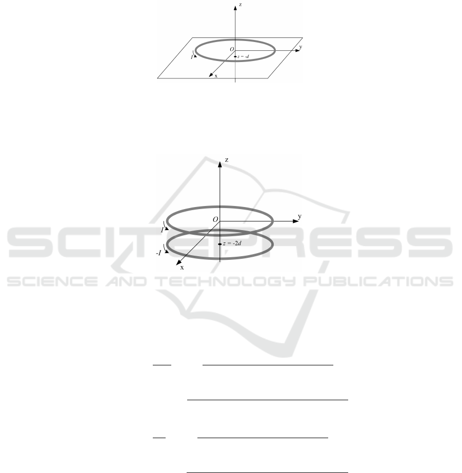
4 The Off-axis Magnetic Field Influenced by a Conducting Plate
Fig. 5, shows a perfectly conducting plate of infinite transversal dimensions located at
the plane z = −d nearby a circular loop antenna (xy-plane). We know that the magnetic
Fig. 5. Circular loop antenna near a perfectly conducting plate.
field at the plane z = −d must be tangential. For z ≥ −d, the configuration shown on
Fig. 6 yields the same solution [6]. As one can see, the loop antenna located at the plane
z = −2d has a current opposite to the original loop antenna. Based on superposition,
Fig. 6. Introduction of the image current.
we can write that for z ≥ −d, equations (7), (8) and (9) are valid.
H
x
(y, z) = 0 (7)
H
y
(y, z) =
Ir
l
z
4π
"
Z
2π
0
sin φ
0
dφ
0
(r
2
l
+ y
2
− 2r
l
y sin φ
0
+ z
2
)
3/2
−
Z
2π
0
sin φ
0
dφ
0
(r
2
l
+ y
2
− 2r
l
y sin φ
0
+ (z + 2d)
2
)
3/2
#
(8)
H
z
(y, z) =
Ir
l
4π
"
Z
2π
0
(r
l
− y sin φ
0
) dφ
0
(r
2
l
+ y
2
− 2r
l
y sin φ
0
+ z
2
)
3/2
−
Z
2π
0
(r
l
− y sin φ
0
) dφ
0
(r
2
l
+ y
2
− 2r
l
y sin φ
0
+ (z + 2d)
2
)
3/2
#
(9)
20
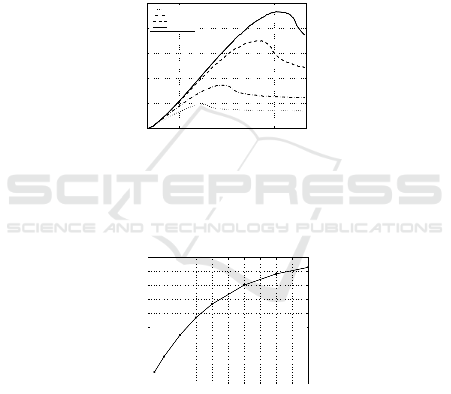
5 Operating Volume Influenced by a Conducting Plate
In section (3), we have shown the importance of choosing an optimal radius depending
on the current through a circular loop antenna. Within this section, we will focus on
the influence of a conducting plate on the operating volume of a loop antenna. The
current I has been chosen equal to 0.14 A. For different distances d, we can calculate
the operating volume, using the same numerical procedure as applied for the circular
loop in free space, Fig. 7.
0 0.1 0.2 0.3 0.4 0.5
0
0.1
0.2
0.3
0.4
0.5
0.6
0.7
0.8
0.9
1
Operating volume [m
3
]
r
l
[m]
d = 0.05 m
d = 0.1 m
d = 0.3 m
free space
Fig. 7. The operating volume is calculated for different values of d with a current I = 0.14 A.
Where the conducting plate is found at a distance d, it is clear that this parameter
limits the operating volume. A second issue is the influence on the radius r
l
where the
highest operating volume is provided. As one can see, the operating volume is increased
when the distance d enlarges. The increase of the maximum operating volume depend-
ing on parameter d, is shown in Fig. 8. In this figure, the radius r
l
is chosen to provide
the largest operating volume.
0 0.05 0.1 0.15 0.2 0.25 0.3 0.35 0.4 0.45 0.5
0
0.1
0.2
0.3
0.4
0.5
0.6
0.7
0.8
0.9
Maximum operating volume [m
3
]
Distance d [m]
Fig. 8. The maximum operating volume is calculated for different values of d.
Especially when the distance d is small, any increase of this distance implies a
significant gain regarding the operating volume.
21

6 Conclusions
In this paper, a numerical procedure to determine the magnetic field generated by a cir-
cular loop in free space or in the vicinity of a metal plane is presented. Based on this
procedure, one can generate theoretical models on how the operating volume of circular
loop antennas will behave when they are surrounded by conductive objects.
This is especially interesting for the usage of RFID systems in industrial application
where metals are ubiquitous and a high reliability is of great importance. We have
shown how the magnetic field of an RFID loop antenna is influenced as the distance
between the conducting plane and the reader decreases.
Although the operating volume is defined by the ISO/IEC 15693 standard as the 150mA-
contour of the total magnetic field, most transponder require an activation field strength
much lower then 150mA/m. Typically the required field strength is between 50 mA/m
and 80 mA/m. This large difference between the minimum activation field strength
specified by the standard and the one needed by the transponders, only enhances the
reliability. This ensures that the transponders will also be detected when the orientation
differs from the optimal orientation (perpendicular to the field lines).
Within this paper we focused on HF RFID systems but, with minor changes, this method
can be extended to the domain of LF RFID, where the operating volume is defined by
the 1.5A/m-contour.
References
1. D’hoe K., Stevens N., Goemaere J.P., De Strycker L. and Nauwelaers B., Design of an RFID
loop antenna in non-ideal conditions, ECUMICT 2010, Belgium: Ghent, 2010, pp. 405-411.
2. Stevens N., De Strycker L. and Verschelde W., Procedure to Calculate the Inductance of a Cir-
cular Loop Near a Metal Plate, EMC Europe 2010, Poland: Wroclaw, 2010, to be published.
3. Identification Cards – Contactless Integrated Circuit(s) Cards – Vicinity Cards – Part 1: Air
Interface and Initialization, 1st ed., Int. Std. ISO/IEC 15693-1, ISO/IEC/JTC1 Inf. Technol.,
2000.
4. Identification Cards – Contactless Integrated Circuit(s) Cards – Vicinity Cards – Part 2: Phys-
ical Characteristics, 2nd ed., Int. Std. ISO/IEC 15693-2, ISO/IEC/JTC1 Inf. Technol., 2006.
5. Identification Cards – Contactless Integrated Circuit(s) Cards – Vicinity Cards – Part 3: Anti-
collision and Transmission Protocol, 1st ed., Int. Std. ISO/IEC 15693-3, ISO/IEC/JTC1 Inf.
Technol., 2001.
6. D. J. Griffiths, Introduction to Electrodynamics, Englewood Cliffs, New Jersey: Prentice
Hall, 1981.
7. Finkenzeller K., RFID Handbook: Fundamentals and Applications in Contactless Smart Cards
and Identification, 2nd ed. New York, NY, USA: John Wiley & Sons, Inc., 2003.
22
