Continuous Maintenance of Multiple Abstraction Levels
in Program Code
Moritz Balz, Michael Striewe and Michael Goedicke
Paluno – The Ruhr Institute for Software Technology
University of Duisburg-Essen, Campus Essen, Essen, Germany
Abstract. During development of software systems multiple notations are in use
to describe requirements, design, source code, run time traces, and more. These
notations usually have different purposes and semantics so that it is difficult to
keep information consistent during development. In this position paper we pro-
pose an alternative approach to model-driven software development that enhances
program code with abstract specification information. Thus the program code can
be considered at different views for design, verification, execution, and monitor-
ing, while information of interest is continuously available in a coherent notation.
1 Introduction
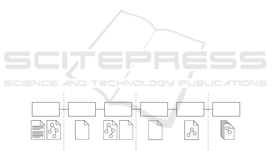
When software systems are developed, several stages are passed through, in which dif-
ferent notations describe certain aspects of the software at different abstraction levels
and with different purposes. This entails that important information is not available con-
sistently; even worse, pieces of information in different notations are hard to synchro-
nize if the software is maintained over longer periods of time. An overview of notations
to encounter is given in figure 1.
Implemen-
tation
Validation &
Verification
Execution
Monitoring
Development Time
Run Time
Design &
Architecture
Design Time
{} {}
01010
10101
01010
Languages
& Models
Source Code Source Code
& Models
Byte Code Tracing
@
Design
Recovery
Replacement
@
}
10
All
Notations
Fig.1. Different stages of development processes and notations that are used to describe the
software or certain aspects of it. While all notations focus on different views of the software, they
are hard to synchronize over time.
At design time, software architecture and functionality are derived from require-
ments and recorded in semi-formalized description languages or formalized models.
Based on this, source code is derived from specifications, either with manual program-
ming or – in the case of some model-drivensoftware development (MDSD) approaches
Balz M., Striewe M. and Goedicke M.
Continuous Maintenance of Multiple Abstraction Levels in Program Code.
DOI: 10.5220/0003026500680079
In Proceedings of the 2nd International Workshop on Future Trends of Model-Driven Development (ICEIS 2010), page
ISBN: 978-989-8425-10-2
Copyright
c
2010 by SCITEPRESS – Science and Technology Publications, Lda. All rights reserved

– with code generation [1]. The notation of the source code belongs to certain general-
purpose programming languages or domain-specific languages (DSLs). Design and im-
plementation can be verified afterwards, either at the level of specifications or of the
programming language [2]. At run time, software is represented by compiled machine
code or byte code containing detailed imperative statements. Running systems can be
monitored, which usually relies on the existence of meta data relating executable code
to specifications [3]. Finally, when software is put out of service, design recovery can
be applied to all existing information to transfer knowledge into successional systems.
These different notations are usually independent and cannot be synchronized auto-
matically because they describe specific aspects only. A general-purpose programming
language in which detailed algorithms are implemented is used in most cases, even
with code generation: When systems cannot be modelled completely, generated code
is amended, tuned, or customized to fit special requirements, APIs, or frameworks [4].
Thus MDSD cannot reduce the number of notations since such code does not integrate
in high-levelspecifications seamlessly. In contrast, attempts to cover all aspects by mod-
eling languages lead to modeling stacks being as complex as programming languages
[5].
On the other hand, program code of modern programming languages became more
and more expressive over time. Fragments of object-oriented languages can be arranged
according to informal or formalized design patterns [6]. In languages providing con-
cepts for type-safe meta data, attribute-enabled programming [7] gives code fragments
additional semantics that are interpretable at development time and run time. We pro-
posed to enhance this to embed model specifications in program code [8,9] by defining
program code patterns representing the abstract syntax of models. By this means pro-
gram code does not only carry implementation details, but also model specifications, so
that different aspects do not require different notations, but are views on the same soft-
ware. Since access to this code is possible with structural reflection [10] at run time, ex-
ecution frameworks can interpret and invoke the fragments and thus execute the model
specifications. This is for example applicable to models that describe the behavior of
(parts of) applications precisely, like state machines or process models.
We will here describe our approach to reduce the number of notations during devel-
opment. We introduce a concept for maintaining multiple abstraction levels in program
code in section 2 and describe its systematic application throughout the development
process in section 3. Afterwards we discuss the approach in section 4, consider related
work with respect to alignment and synchronization of such notations in section 5, and
conclude in section 6.
2 Multiple Abstraction Levels in Program Code
Above we stated the goal to reduce the number of notations present in many software
development activities. However, it is not desirable to reduce the number of views on
the software since different abstraction levels fulfill different purposes, especially if
formal specifications are used. Thus it is necessary to decouple notations and views. We
decided to enhance the idea of design patterns with respect to formal models and make
the program code interpretable for different views. Since model specifications are by
69
Contract Definition in Source Code
public class AfterMeasurementState implements IState
{
@Transition(target = UpUpState.class , contract = BeginUpUpContract.class )
public void beginUpUp(MeasurementModule actor) throws MeasurementAbortedException
{
actor.doMeasure ();
}
// ...
}
State Definition
Target State Pointer
Contract Pointer
Action Label
Transition
State and Transition Definition in Source Code
}
public class BeginUpUpContract implements IContract< IMeasurementVariables >
public boolean checkCondition( IMeasurementVariables vars )
{
return (!vars.getAbort() && !vars.getRestart() && vars.getTooLow());
}
{
public boolean validate( IMeasurementVariables before , IMeasurementVariables after )
{
return ( after.getNumberOfWorkers() == ( before.getNumberOfWorkers() + before.getWorkerDistance()) );
}
Contract Definition
Variable DefinitionsCurrent Variable Values
Guard
Update
Variable Labels
Current Variable Values
Cached Variable Values
Variable Labels
Fig.2. A state definition with an outgoing transition and its contract. The first method of the
contract checks a pre-condition with the current variable values, while the second method checks
a post-condition by comparing the current values to previous values.
this means embedded in the program code structures, the approach is called “embedded
models”.
2.1 Example
An exemplary embedded model for state machines is shown in figure 2. It is imple-
mented by a set of classes, each marked by interfaces to be a “state” or “contract”
class. The class at the top is a state class whose unique name represents the state’s
name. Methods in state classes are marked as transitions by a Java meta data annotation
@Transition whose attributes refer to the target state and a contract class (bottom
of figure 2) containing guards and updates. An interface type referred to as “actor”
is passed to transition methods. Its methods are interpreted as action labels which are
called when the transition fires.
Guards and updates are implemented as two methods in a contract class, both eval-
uating boolean expressions. In case of guards (method checkCondition), the re-
turned boolean value decides whether the related transition may fire or not. They use
the current variable values of the state machine for this decision. In case of updates
(method validate), the returned boolean value indicates whether variables match
70
the expected value or value range after actions have been performed. Therefore updates
compare the current values with the values from the point in time before the transition
fired to validate the changes to the state space. Both methods access a “variables” type
which is a facade type representing the variables constituting the state space of the state
machine, thus allowing an abstraction over the state space of the whole system. The
“variables” type contains “get” methods for each variable, which are by this means de-
fined with a label and a data type and which may return aggregated data in order to
realize the abstractions named above.
2.2 General Approach
The program code introduced above is interpretable at different abstraction levels, e.g.
some lines of code are both a method in terms of the programming language and a
transition in terms of the state machine model. Considering the domain-specific nature
of these different abstraction levels, the program code must be prepared to represent
different abstraction levels for each embedded model. The principle for all domain-
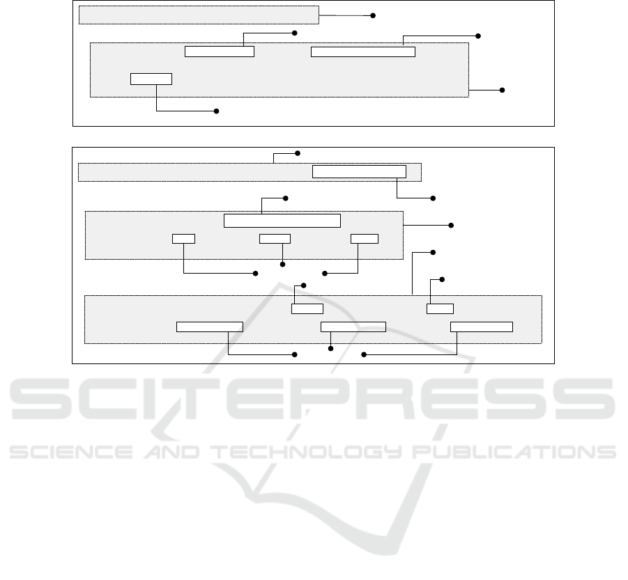
specific views is illustrated in figure 3.
Program Code Pattern
Interfaces
Other Code
Specifications
Execution
Framework
Transformation
Program Code
Model n
...
Model 1
Model-to-Model
Transformations
Fig.3. The elements of an embedded model definition relating program code to model spec-
ifications at higher levels of abstraction. Code formed following the pattern is executed by a
framework and connected to other code by appropriate interfaces.
First, the model specifications of interest must be defined. Since not all models are
backed by common meta models the specifications can be very different and no gen-
eral definition can be given. However, the following kinds of elements can be expected:
Static elements represent static structures and their relations. A logic for expressions
describes dynamic aspects by connecting static structures with logical formulas. Ele-
ments or entities outside a model can be referenced by labels that provide appropriate
names. Connections between static structures and formulas are realized by functions
that arrange and combine model elements.
Based on this the core of the embedded model can be defined: A program code
pattern arranges program code fragments so that they are interpretable with respect
to model specifications. Considering programming languages like Java or C#, a set of
appropriate fragments is available: Static structures can be represented by types, meth-
ods, and annotations. Their relations can be defined with parameter types, containment,
and inheritance hierarchies. Considering formulas, appropriate expressions at least for
propositional logic exist. Connections between static structures and/or expressions can
be represented in program code in different ways, for example with annotations or con-
tainment. The pattern definition distinguishes two types of program code fragments:
71

Some of the code is created per instance, i.e. for one concrete model, following certain
rules how fragments must be arranged to represent the model syntax. Such rules may
imply the use of certain types, interfaces, or meta data definitions that can be identi-
fied by tools. These are pre-defined, i.e. specified and implemented when an embedded
model definition is created and shared among implementations afterwards.
At the level of the program code the patterns describe model instances. This descrip-
tion entails that no detailed execution information is contained in the program code,
since this would mix high-level specifications with algorithmic details. For this reason
execution is realized by frameworks that access the program code following the pattern
by reflection. Interpretation and invocation of code fragments at run time thus result in
a sequence of events and data flow matching the semantics of the formal model.
Embedded models are not self-contained, but part of arbitrary program code so that
well-defined interfaces realize abstractions between model specifications and other pro-
gram code. Data-oriented abstraction means that data read from the program code into
the model may be aggregated, thus one value delivered to the model may be composed
of many variable values in the program code. For action-oriented abstraction, meth-
ods provide entry points to arbitrary business logic which is referenced in the model,
thus abstracting from the actual implementation in the program code. By this means
every abstraction between model and actual implementation is explicitly visible in the
interfaces.
When the program code pattern is by this means defined, it can be considered at dif-
ferent abstraction levels. For this reason transformations extract view-specific informa-
tion from program code. Internal transformations provide non-persistent views on the
code so that no additional notation is necessary. This is desirable since changes in one
view are reflected in the others directly. However, external notations may be necessary,
for example if specific tools require certain file formats or if models are communicated
outside the actual development so that program code is not usable. In this case external
transformations translate model information from a program code pattern into external
notations. If these notations carry the information of the formal model completely, it
can also be transformed or merged back to program code unambiguously.
With these elements of an embedded model definition the program code can carry
information at different abstraction levels. We will now describe the systematic use of
this information throughout the development process.
3 Development Process
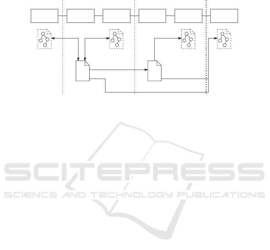
Program code containing embedded models with information at different abstraction
levels can be the primary notation during development, so that the number of notations
can be reduced as shown in figure 4: Only source code and compiled program code
are needed as explicit notations, with the compiled code being derived from the source
code. During design, verification, monitoring, and design recovery, the models are spe-
cific views on the program code that are extracted on demand. We will now explain the
use of embedded models in the development process in detail for the exemplary domain
of state machines.
72
Implemen-
tation
Validation &
Verification
Execution
Monitoring
Development Time Run Time
Design &
Architecture
Design Time
{}
01010
10101
01010
Design
Model Views
Source Code
Verification
Model Views
Byte Code
Monitoring
Model Views
Design
Recovery
Replacement
Design
Model Views
Trans-
formation
Compilation
Trans-
formation
Trans-
formation
Trans-
formation
Fig.4. Different views on source code and compiled byte code during development which are
provided by unidirectional and bidirectional transformations. The views may rely on separate
notations, but the essential modeling information is available in the program code in any case.
3.1 Design and Implementation
When the program code carries design information as well as the actual implementa-
tion, the related activities in the development process are not clearly separated. During
design, we expect two use cases for embedded models:
First, models are usually defined in dedicated notations of modeling tools. Such
models can be refined and/or exchanged between tools with appropriate model-to-
model transformations where source and sink carry the semantics of the models so
that the transformation is unambiguous. This does usually not apply to program code
since it contains detailed execution logic only. However, program code patterns with
their expressiveness can participate in model transformations: With external transfor-
mations (compare section 2.2), program code structures can be created as a result of
model transformations, and modeling information can be extracted from the code and
used in other notations.
Second, modeling can be used to create the program code directly. This is useful
if the design is not that complex that it requires external notations. In this case design
tools create program code directly from visual representations, for example for state
machines. The design information is thus only a different view on the system to de-
velop and by this means an internal transformation between model specifications and
the program code.
3.2 Verification
When program code has been designed and implemented with embedded models, the
contained modeling information allows for verification at different abstraction levels.
However,verification with respect to models relies not only on the existence of a model,
but also of a specification the model is verified against. Thus appropriate views must
73

provide model specifications and interpret the embedded model accordingly. For this
purpose subsets of the modeling information that are of interest are extracted from the
program code. Any abstraction or refinement explicitly happens alongside interfaces or
pre-defined types.
For state machines we developed an external transformation into timed automata
[8] to verify them in the model checker UPPAAL [11]. By generating states out of
state classes, transitions out of transition methods, guards and updates out of contracts,
and model variables out of the respective facade type methods, a formal state machine
model can be extracted from the code and checked e.g. for deadlocks. More precise,
this allows to check the actual implementation against a formal specification instead of
just checking the models.
Since embedded model interfaces are interpretable with respect to model semantics,
assertions can be made about other code connected with them. These assertions are
based on the semantics of the interfaces, for example with the existence of pre- and
post-conditions surrounding method calls. In state machines, the update information in
contract classes can be used as additional assertions for continuous validation with real
data during run time, thus implicitly checking the whole system behavior against the
abstract model.
For the same reason, views for static analysis can determine if other program code is
valid with respect to the model specifications it is interacting with. In addition, dynamic
analysis and model checking (for example with Java PathFinder [12]) are applicable to
validate data exchange and state spaces at run time. In this context an embedded state
machine eases any static analysis based on slicing since transitions offer natural starting
points for slices. In general the patterns used to structure the code with respect to any
class of models can be used to structure the verification process and reduce the search
space.
3.3 Execution
After compilation in Java, the resulting bytecode contains most static structures like
classes and methods and provides access to them with structural reflection at run time.
However, this has limitations since not all source code semantics are available; for ex-
ample, Java reflection treats method contents as black boxes. In this context embedded
models are executed by frameworks using reflection for reading, interpreting, and in-
voking program code. The resulting sequences of actions adhere to the semantics of the
underlying formal model. Execution is thus a specific view on compiled program code
that accesses modeling information to create sequences of actions.
Considering execution semantics of state machines, the model is connected to busi-
ness logic during transitions, and the paths through the state machine depend on deci-
sions in guards and thus on variable values. The purpose of the state machine is thus to
invoke actions in an appropriate sequence. The execution framework instantiates state
classes beginning with the initial state. It reads annotations in transition methods after-
wards and instantiates contract classes referenced there. Then the guard methods are
invoked and the variables are passed to them, and the result is used to determine if the
related transition will fire. The next state is then determined from the class reference
given in the annotation, and the procedure is repeated until a final state is reached.
74

3.4 Monitoring
Compiled code with embedded models is interpretable for tracing and monitoring with
respect to the model specifications. This is of interest since embedded models interact
with other business logic and use real data at run time. Thus more complex state spaces
can exist than those used for verification. For monitoring, traces in terms of class in-
stantiations, method calls, and changes of variable values can be generated. Two kinds
of monitoring can be distinguished:
Active monitoring is controlled by the execution framework notifying listeners so
that appropriateviews can be realized at the levelof the framework.However,the degree
of detail is limited by the platform’s reflection capabilities, and overhead introduced by
interpretation and emission of information must be considered for productive systems.
Passive monitoring relies on instrumentation techniques of the platform. In Java the
debugging interface is appropriate to gather information about running software. Since
program code patterns define entry points into program code, instantiations and invo-
cations of that code can be surveyed. Passive monitoring can be applied to all elements
of the programming language, including method contents, so that a running embedded
model can be considered in detail. However, noticeable overhead of instrumentation
techniques entails that this will not be usable in production environments.
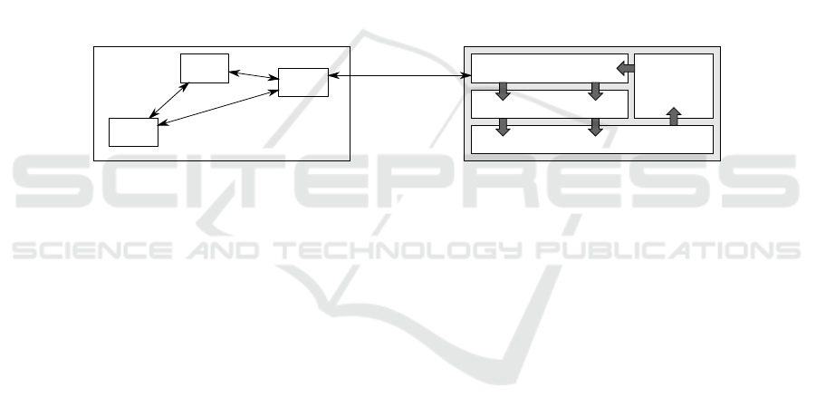
For state machines the following information is of interest: (1) Initialization and
start of a state machine with information about all states, transitions, and variables as
extracted from code; (2) activation of states indicating that guard evaluation and tran-
sition selection in this state will happen subsequently; (3) selection of transitions in-
dicating that program control will be handed over to business logic; (4) validation of
updates after transitions with a comparison of current variable values and cached vari-
able values from the point in time before the transition fired. With an appropriate tool
as shown in figure 5, an embedded state machine can be analyzed with respect to a
graphical representation highlighting active states and transitions, variable values, and
guard evaluation.
In summary, the views used at development time can be transferred to the run time
when the well-defined program code structures are executed.
3.5 Design Recovery
When software is put out of service, data and business logic are often to be transferred
to successional systems. However, experience shows that documentation is often in-
complete, out of sync with the actual system, or not existent at all. Especially modeling
information would in such cases be of help since model specifications are often used to
describe essential parts of the system that may be of interest for reengineering or can
support the recovery of design in the software.
Modeling information in source code or byte code can be accessed as described for
design, verification, execution, and monitoring. It is appropriate for reengineering and
design recovery since it is no external meta data, but constitutes (a part of) the actual
system that is to be replaced. Thus embedded models support design recovery if basic
information about their use is available.
75
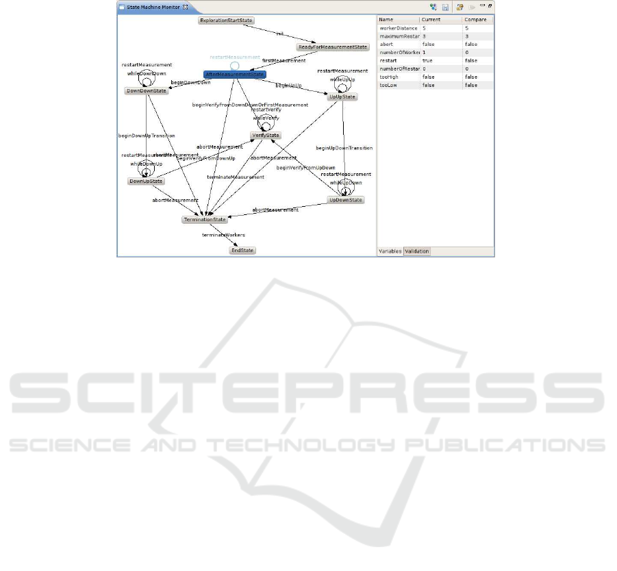
Fig.5. A state machine view realized by a monitoring tool. It shows selection of states and tran-
sitions as well as variable values and evaluation of guards and updates.
4 Discussion
The approach presented here is contrary to other MDSD approaches since it consid-
ers program code not as result derived from abstract specifications, but the primary
notation containing information about models. We chose this approach because pro-
gram code is an integral part of most software development activities: When complex
requirements, specific libraries or frameworks, or performance requirements demand
non-standardized solutions, model specifications cannot cover complete applications
under development. This leads to situations where a semantic gap exists between model
specifications and the actual program code that is derived from them or must interact
with derived code. The use of different notations thus increases complexity which is not
reduced by tools unambiguously.
Embedded models are therefore applicable when domain-specific models are used
in programs where developers have to work with program code explicitly. In such cases
the tight integration of specifications and program code as described in this contribu-
tion is desirable from our point of view and can be used throughout the development
process. Notations that are only used to provide domain-specific views on the program
code can be replaced by appropriate program code patterns for design, verification, exe-
cution, monitoring, and design recovery of software. The approach has so far been eval-
uated in the development of mid-sized real-world applications [13]. The development
activities described in this contribution are already supported by tools that interpret the
program code at development time and run time and provide specific views for differ-
ent purposes. However, different semantic gaps can be expected for different modeling
classes, so that further research is necessary to determine the applicability of embedded
models.
76

In summary, we are convinced and have partly evaluated that embedded models are
appropriate for the given use case of application development.
5 Related Work
We consider work related to this contribution that aims either at reducing the number
of different notations in use during development or at seamless synchronization with
respect to formal models.
While model round-trip engineering identifies relations between program code and
models, it requires manual effort since modifications in the code cannot always be inter-
preted with respect to semantics of abstract models [14]. In contrast, embedded models
only consider program code that follows the syntax of program code patterns and is
therefore interpretable unambiguously. Several approaches relate source code to high-
level specifications using meta data, e.g. [15], thus enhancing its formal description at
the same abstraction level while using different notations. Similar, framework-specific
modeling languages consider the semantics of frameworks to enable continuous round-
trip engineering at this abstraction level [16]. Different to these approaches, embedded
models focus on establishing relations between different abstraction levels.
In contrast to Internal DSLs [17], embedded models allow not only to interpret
statements, but more complex static structures in the code. Other than design patterns
specified with respect to modeling languages [18], embedded models are completely
founded on formal model semantics. In difference to modeling constraints in object-
oriented source code [19] or model checking for source code [12], embedded models
do not focus on verification of the program code itself, but on its relations to high-level
specifications.
While execution of model specifications like UML diagrams [20], constraint or ac-
tion languages [21], or DSLs [22] leads to a clean and model-centric view of systems,
it requires complete modeling of applications or integration of modeling notations with
program code. Program code patterns of embedded models, in contrast, are invoked ac-
cording to the execution semantics, while all information is embedded in the program
code.
In summary, these related approaches are not appropriate to either reduce the num-
ber of notations in use during development or enable a seamless synchronization that
considers formal models as well as program code.
6 Conclusions
In this contribution we presented an approach to reduce the number of notations used
during software development if the implementation is based on model specifications.
Since program code is explicitly available in many projects, we considered the expres-
siveness of modern object-oriented general-purpose programming languages and en-
hanced the idea of design patterns with program code patterns that represent the syntax
of models. By this means less notations are required since the program code itself is
interpretable at different levels of abstraction. The resulting domain-specific views on
the program were discussed with the example of state machines for design, verification,
77

execution, monitoring, and design recovery of software. Embedded models are thus ap-
plicable for software under developmentthat uses domain-specificmodels together with
program code that is not based on models. Since the development activities described
here have been evaluated in mid-sized real-world applications and are supported by
appropriate tools we can state that the approach is feasible.
Future work will focus on extending the concept with respect to different aspects.
First the transfer to other modeling domains will be of interest which will include com-
pletely different modeling domains like components,ontologies, or rules. In this context
the integration in meta-modeling languages (like UML’s OMF) and model interactions
will be of interest, both with the objective to cover larger parts of applications under
development and leverage the principle of working with only one notation for different
abstraction levels.
References
1. Hailpern, B., Tarr, P.: Model-driven development: The good, the bad, and the ugly. IBM
Systems Journal 45 (2006) 451–461
2. Holzmann, G.J., Joshi, R., Groce, A.: Model driven code checking. Automated Software
Engineering 15 (2008) 283–297
3. Bodden, E.: The Design and Implementation of Formal Monitoring Techniques. In: Com-
panion to the 22nd Annual ACM SIGPLAN Conference on Object-Oriented Programming,
Systems, Languages, and Applications, OOPSLA 2007, October 21-25, 2007, Montreal,
Quebec, Canada, ACM (2007) 939–940
4. Vok´aˇc, M., Glattetre, J.M.: Using a Domain-Specific Language and Custom Tools to Model
a Multi-tier Service-Oriented Application – Experiences and Challenges. In Briand, L.,
Williams, C., eds.: Model Driven Engineering Languages and Systems, 8th International
Conference, MoDELS 2005, Montego Bay, Jamaica, October 2-7, 2005, Proceedings. Vol-
ume 3713 of LNCS., Springer (2005) 492–506
5. Fowler, M.: PlatformIndependentMalapropism (2003) http://www.martinfowler.com/bliki/
PlatformIndependentMalapropism.html.
6. Mikkonen, T.: Formalizing Design Patterns. In: ICSE ’98: Proceedings of the 20th interna-
tional conference on Software engineering, Washington, DC, USA, IEEE Computer Society
(1998) 115–124
7. Schwarz, D.: Peeking Inside the Box: Attribute-Oriented Programming with Java 1.5. ON-
Java.com (2004) http://www.onjava.com/pub/a/onjava/2004/06/30/insidebox1.html.
8. Balz, M., Striewe, M., Goedicke, M.: Embedding State Machine Models in Object-Oriented
Source Code. In: Proceedings of the 3rd Workshop on Models@run.time at MODELS 2008.
(2008) 6–15
9. Balz, M., Goedicke, M.: Embedding Process Models in Object-Oriented Program Code. In:
Proceedings of the First Workshop on Behavioural Modelling in Model-Driven Architecture
(BM-MDA). (2009)
10. Demers, F.N., Malenfant, J.: Reflection in logic, functional and object-oriented program-
ming: a short comparative study. In: In IJCAI ’95 Workshop on Reflection and Metalevel
Architectures and their Applications in AI. (1995) 29–38
11. Larsen, K.G., Pettersson, P., Yi, W.: UPPAAL in a Nutshell. Int. Journal on Software Tools
for Technology Transfer 1 (1997) 134–152
12. Visser, W., Havelund, K., Brat, G., Park, S., Lerda, F.: Model Checking Programs. Auto-
mated Software Engineering Journal 10 (2003)
78

13. Striewe, M., Balz, M., Goedicke, M.: SyLaGen - An Extendable Tool Environment for
Generating Load. In Mller-Clostermann, B., Echtle, K., Rathgeb, E., eds.: Proceedings of
”Measurement, Modelling and Evaluation of Computing Systems” and ”Dependability and
Fault Tolerance” 2010, March 15 - 17, Essen, Germany. Volume 5987 of LNCS., Springer
(2010) 307–310
14. Demeyer, S., Ducasse, S., Tichelaar, S.: Why Unified is not Universal? UML Shortcomings
for Coping with Round-trip Engineering. In: UML’99: The Unified Modeling Language
- Beyond the Standard, Second International Conference, Fort Collins, CO, USA, October
28-30, 1999, Proceedings. (1999) 630–644
15. Serugendo, G.D.M., Deriaz, M.: Specification-Carrying Code for Self-Managed Systems.
In: IFIP/IEEE International Workshop on Self-Managed Systems and Services. (2005)
16. Antkiewicz, M.: Round-trip engineering using framework-specific modeling languages. In:
OOPSLA ’07: Companion to the 22nd ACM SIGPLAN conference on Object-oriented pro-
gramming systems and applications companion, New York, NY, USA, ACM (2007) 927–928
17. Freeman, S., Pryce, N.: Evolving an Embedded Domain-Specific Language in Java. In:
OOPSLA ’06: Companion to the 21st ACM SIGPLAN Symposium on Object-oriented Pro-
gramming Systems, Languages, and Applications, New York, NY, USA, ACM (2006) 855–
865
18. Mak, J.K.H., Choy, C.S.T., Lun, D.P.K.: Precise modeling of design patterns in uml. In: ICSE
’04: Proceedings of the 26th International Conference on Software Engineering, Washington,
DC, USA, IEEE Computer Society (2004) 252–261
19. Beckert, B., Hhnle, R., Schmitt, P.H.: Verification of Object-Oriented Software. The KeY
Approach. Springer-Verlag New York, Inc. (2007)
20. Starr, L.: Executable Uml: How to Build Class Models. Prentice Hall PTR, Upper Saddle
River, NJ, USA (2001)
21. Raistrick, C., Francis, P., Wright, J.: Model Driven Architecture with Executable UML.
Cambridge University Press, New York, NY, USA (2004)
22. Hen-Tov, A., Lorenz, D.H., Schachter, L.: ModelTalk: A Framework for Developing Domain
Specific Executable Models. In: Proceedings of the 8th OOPSLA Workshop on Domain-
Specific Modeling. (2008)
79
