
EVALUATION OF AN INDOOR NAVIGATION APPROACH BASED
ON APPROXIMATE POSITIONS
Ory Chowaw-Liebman, Uta Christoph, Karl-Heinz Krempels and Christoph Terwelp
Informatik 4, Intelligent Distributed Systems Group, RWTH Aachen University, Aachen, Germany
Keywords:
Indoor navigation, Mobile computing, Device whispering, Context-based services.
Abstract:
Until now navigation aids have primarily focused on outdoor scenarios, whether driving on highways or, more
recently, walking through cities. These systems use the Global Positioning System (GPS) for position infor-
mation. Indoor navigation however cannot rely on GPS data, as the signals do not penetrate building structure.
Thus other techniques are required to provide position information indoors. In this article the approach to an
indoor navigation system based on the position information provided by the Device Whispering technique is
presented. The position information acquired by Device Whispering is less precise than information acquired
by the Fingerprinting technique but more robust. To compensate the deficit of precision the position informa-
tion is combined with a movement model. This movement model is automatically generated from the maps
which are already required for navigation.
1 INTRODUCTION
Tools for navigational assistance have become an es-
sential element in today’s traveling society. Interac-
tive software, available for mobile phones, is capable
of guiding users who are driving cars, riding bicycles
or walking. Until now such tools have focused on out-
door environments and are hence based on the precise
data of the Global Positioning System (GPS) to deter-
mine the current position of the device, and thus the
user. But indoor navigation bears several challenges.
First, GPS positioning information cannot be used
for indoor scenarios since GPS radio signals do not
propagate into buildings.
Second, within buildings navigation does not rely
on streets or footpaths but on traversable areas and
certain connections between such, e.g. corridors,
rooms, staircases and elevators. Thus such areas and
also the altitude of the user, i.e. the floor he is cur-
rently standing on, and possible connections to other
floors have to be considered.
Third, the description of a path needs to be intu-
itively understandable for humans instead of precise
distance instructions as they are used in cars or other
devices with odometers.
The first issue, a positioning technique for indoor
scenarios, was addressed among others in (Wallbaum
and Spaniol, 2006). The third issue on intuitive navi-
gational instructions is considered for outdoor envi-
ronments in (Dale et al., 2003). Section 2 gives a more
detailed overview. Based on this current state of the
art a prototype indoor navigation system was devel-
oped and implemented as a software client for a mo-
bile device with WLAN interface (Chowaw-Liebman
et al., 2009), (Chowaw-Liebman, 2009), which is de-
scribed in Section 3. Central data structure of the
system is the Map, described in Section 4, which
also specifies how the Map is generated from user in-
put. Section 5 summarizes the text generation method
used by the prototype to generate natural language in-
structions for routes. Finally, Section 6 concludes this
paper and shows some directions for future work.
2 STATE OF THE ART
This section briefly reviews previous work on indoor
positioning and natural language generation as basis
for our indoor navigation approach.
2.1 Fingerprinting
Fingerprinting (Ohlbach et al., 2006) is an indoor po-
sitioning method based on wireless networks. The
main goal of the Fingerprinting project is to pro-
vide precise position information. The approach is
basically a pattern matching of the received signal
strengths (RSS) for all APs at a position. The RSS at
195
Chowaw-Liebman O., Christoph U., Krempels K. and Terwelp C. (2010).
EVALUATION OF AN INDOOR NAVIGATION APPROACH BASED ON APPROXIMATE POSITIONS.
In Proceedings of the International Conference on Wireless Information Networks and Systems, pages 195-201
DOI: 10.5220/0003032601950201
Copyright
c
SciTePress

the user’s current position are matched to a database
of RSS measurements at known locations, the finger-
prints. When combined with user tracking and a ”no
teleporting” policy, the achieved precision is reported
to be approximately 1 meter.
2.2 Device Whispering
The Device Whispering technique is also an indoor
positioning approach based on wireless network in-
frastructures. The main idea is to reduce the number
of access points (APs) considered for position estima-
tion to those that are closest in range. This is achieved
by controlling the transmitting power of the WLAN
interface: The device is set to minimum power before
performing an active network scan. The closest AP is
defined as the one answering to the request with the
lowest transmission power used, which is the mini-
mum information possible.
APs can be tagged with geopgraphical position in-
formation, and if multiple APs are available these tags
can be used to approximate the current position of
the user more precisely than just assigning the closest
AP. Various caveats are discussed in (Krempels et al.,
2009).
The method’s lack of precision makes it neces-
sary to use a novel navigation approach, as current
solutions assume precise information. This paper de-
scribes an approach specifically designed for use with
the Device Whispering technique.
2.3 CORAL
The CORAL system (Dale et al., 2003) is a natural
language instruction generator designed to enhance
existing outdoor navigation tools, accepting route de-
scription in standard formats. In addition, CORAL is
dependent on a geographic information system (GIS)
for additional data about the geography traversed by
the route. The GIS is required to provide landmarks
(like traffic lights, churches and other easily visible
objects) with which the text decription is augmented.
3 PROTOTYPE NAVIGATION
SYSTEM
Any navigation system must convey the route to the
user, typically using a combination of graphical map
(with highlighted path) and textual instructions.
A convenient way to provide route information to
users are natural language instructions (NLI), which
offer rich and flexible means of describing paths.
Figure 1: Components of the navigation system.
NLI, when created by people, are heavily based
on landmarks. Landmarks are distinctive features of
the local geography, e.g. churches, malls, fountains
and traffic lights outdoors, and specific shops, foun-
tains and staircases indoors. To that effect landmarks
are also used by the CORAL system in its descrip-
tion of (outdoor) routes. One important distinction
of indoor scenarios are different floors in a building,
which add a third dimension to the geography of a lo-
cation. Landmarks can also represent connections be-
tween floors, e.g. stairs and elevators, which cannot
be displayed at all in a purely two dimensional map.
This is the approach taken by the Map data structure
of our system.
This prototype system is shown conceptually in
Figure 1, it is centered around the ”Map” data struc-
ture, which makes all navigation information avail-
able to the client software. The dashed parts, repre-
senting the use of a local server are not implemented
by the prototype implementation. In a commercial
system this server would be responsible for providing
information to visitors of the location, most important
the Map, as well as location specific services and con-
text sensitive information and commands (CSCI). See
(Schilit et al., 1994) for further information on these
features.
In our decentralized approach every location is re-
sponsible for providing the information locally, for in-
stance by using the local WLAN infrastructure which
can be assumed to be available since it is used by the
whispering technique for localization. Thus, it is not
required to establish a network link to the user’s mo-
bile provider to equip the mobile devices with up-to-
date Maps. The prototype implementation however
provides the Map through a data file saved on the mo-
bile device.
The Map is generated by a preprocessor, which
provides a GUI to create and maintain the Map data
structure. The ”Admin” in Figure 1 is the person re-
sponsible for maintaining a location’s Map, by pro-
viding the data which is needed by the preproces-
sor. In the Map data structure locations are geomet-
rically described by polygons, inside which the APs
and landmarks are positioned. Section 4 describes
how this input data is converted to a location represen-
WINSYS 2010 - International Conference on Wireless Information Networks and Systems
196

tation based on hierarchical graphs. This conversion
allows for an efficient use of the location data which is
of particular importance for mobile clients. The Map
is made available to the client software which is re-
sponsible for all interactions of the system with the
actual end users.
The client software is supposed to run on mobile
devices, which do not have the computational power
and memory available to notebooks or desktop com-
puters. Therefore, a preprocessor was developed to
perform the computationally intensive tasks before-
hand. The client is left with the tasks of comput-
ing routes in the provided Map, communicating these
routes to the user both graphically and verbally per-
form positioning.
4 MAP
The Map data structure is the central element of the
system which encodes all known information about
a location. The two main goals of the data structure
are adaptation to the imprecise position returned by
the Device Whispering technique and support of the
generation of NLI.
Both landmarks and geometry, can be assigned
descriptive ”features”, which provide nouns to de-
scribe elements of the location. The prototype im-
plementation uses a small ontology including words
like ”corridor”, ”room”, ”elevator” and so on for ob-
jects and specific parts of locations typically encoun-
tered within (public) buildings. These features are
used during text generation to assign nouns, verbs and
articles , so that these landmarks and polygons can de-
scribe a route in natural language.
4.1 Data Structure
The Map is basically represented by a hierarchical
graph, where nodes can contain a sub-graph. Our
Map uses a hierarchy of four levels summarized in
Table 1. For indoor navigation, ”Building” is an in-
tuitive title for the root node, which contains floors.
The child nodes of the floors represent the traversable
geography of the location in a two dimensional way.
The geometry is represented by “sectors” which also
take into account the local distribution of access
Table 1: Levels of the Map’s hierarchical graph.
0
Building
1 Floors
2 Sectorization (Rooms, Corridors)
3 Micro Paths (Skeletons)
points. The sectorization process will be described
below.
Finally, the lowest level of the hierarchy contains
skeletons of the sectors (which are polygons), used
mostly to describe traversal of concave sectors which
occur at corners and intersections. These skeletons
form the basic elements of the paths for which text
instructions are generated.
Two nodes in different sub-graphs can be con-
nected if their parent nodes are connected. This re-
lationship is also invariant in the other direction, i.e.
if two nodes are connected, at least one connection
between the sub-graphs exist. This ensures that a
path on one level of the hierarchy also implies a path
through the sub-graphs of the path’s nodes.
This is an important property when the paths are
to be computed by refining paths along the lower lev-
els of the hierarchy. This incremental approach to
route finding can reduce the time required to com-
pute routes, as large parts of the graph need not be
considered in each step. For example, if a route on
hierarchy level 1 goes from floor 1 to floor 5 using
an elevator, there is no need to consider any other
floors during route finding on level 2. The nice prop-
erties of this approach come at the cost of complex
book-keeping, which can be avoided by computing
the complete route on the skeleton level directly.
In any case, start and goal nodes on the skeleton
level have to be found (from there the hierarchy can
be traversed to the coarser levels). The starting node
is chosen to be the skeleton node closest to the users
position. To determine the goal node, the skeleton
edge closest to the goal landmark is considered: from
the two nodes terminating the edge, the one farther
away from the user’s position is used to ensure the
edge under consideration is part of the route.
The prototype implementation selects the node
with the greater Euclidean distance to the current po-
sition, ignoring the geography. This worked well for
the test Map, which represented Terminal 1 of the
Cologne/Bonn Airport. Another option is to just take
any of the two nodes, and add the edge to the route
if the wrong node was selected. The latter approach
may be more stable for some geometries.
The Device Whispering technique defines a map-
ping from points in space to the closest AP. This prob-
lem
1
has been studied in various fields under various
names. In computational geometry this kind of map-
ping is known as Voronoi diagrams, where it plays an
important role in various applications (Aurenhammer,
1991; Aurenhammer and Klein, 2000). Consequently,
efficient algorithms to compute Voronoi diagrams
have been devised, the best known being Fortune’s
1
Also known as the post-office problem.
EVALUATION OF AN INDOOR NAVIGATION APPROACH BASED ON APPROXIMATE POSITIONS
197
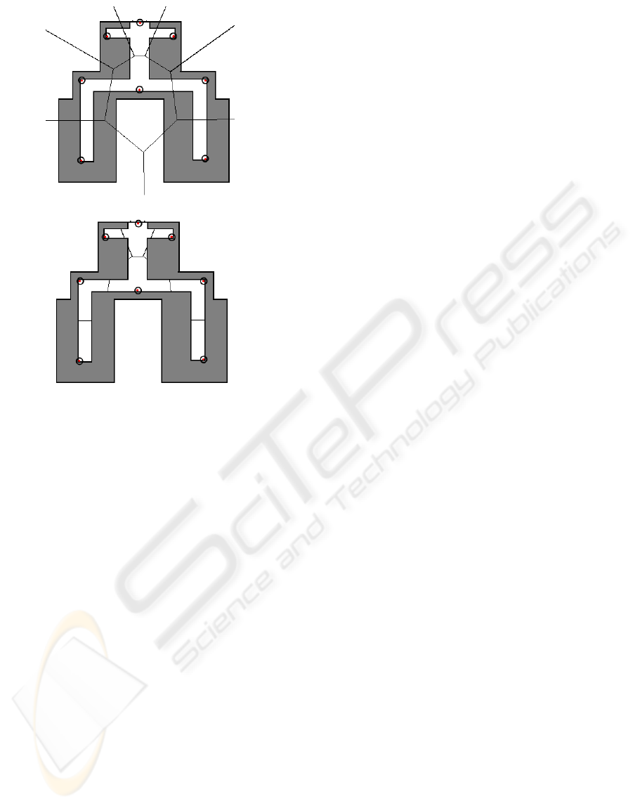
Figure 2: A simple location, access points are the circled
dots. The upper image shows the Voronoi regions gener-
ated from the access points. In the bottom picture, the re-
gions have been clipped to the corridors. Artifact regions
generated during clipping can be seen top center below the
cross corridor.
algorithm described in (Fortune, 1986). The voronoi
diagram assignes a polygon (called the Voronoi re-
gion) to every AP such that the mapping describes at
the paragraphs beginning can be solved by point-in-
polygon queries.
These voronoi regions, computed from the APs
positions, are clipped to the polygons used to describe
the location. The sectorization process is illustrated
in Figure 2. The polygons resulting from the clip-
ping stage are also called “sectors” and are assigned
to nodes on level two of the Map. Nodes are con-
nected if their associated sectors share an edge.
Several algorithms to clip simple polygons ex-
ist, all are based on finding intersections between the
polygons and then traversing the resulting contours,
jumping between the two polygons in such a fashion
that the resulting shape is the desired combination of
the two polygons. One such algorithm is described in
(Weiler and Atherton, 1977).
The second goal, the generation of NLI for a route,
needs to address two requirements:
1. While traversing the route, a user passes by sev-
eral landmarks, namely those contained in the
sectors which are part of the route. The land-
mark’s order of traversal depends on the direction
in which the user is walking within the sector.
2. Sectors can have complex shapes which are dif-
ficult to describe with words. Specifically cor-
ners and intersections are difficult to extract from
a polygon alone, and difficult operations are to
be avoided on mobile devices. The Map should
therefore be able to describe a concave polygon’s
shape.
Both issues are addressed in the Map data struc-
ture by the inclusion of polygon skeletons on the low-
est level of the hierarchy.
4.2 Map Generation
The generation of the Map proceeds by issueing a
node and sub-graph for every “floor” level, which are
connected if landmarks inside the floor are flagged as
connected. This is done by the administrator when
creating a Map with the preprocessor. The floors’
immediate child nodes are associated with the poly-
gons generated during sectorization. Two sector level
nodes are connected by an edge if their associated
polygons share an edge. The sectors polygons are cre-
ated by clipping the polygons describing the locations
geometry to the voronoi regions computed for the ac-
cess points.
The nodes on the sector level are also associated
with those landmarks and APs which are located in-
side the associated polygon. In the case of APs this
is at most one AP, the one contained inside the sector
(a polygon), which is unique due to construction. But
sectors which do not contain any APs can also occur
as can be seen in Figure 2.
Such “artifact” sectors are treated in the next step
of the algorithm by simply associating them with
the access points from those connected sectors which
do contain an AP, based on the fact that whispering
should classify all those APs among the closest ones.
This assignment strategy is used instead of using all
neighbors, which includes neighbors which were as-
signed APs in this step, and avoids sets of APs depen-
dent on the order in which they are created.
The nodes on the lowest level, representing the
skeleton, are associated with single points, the posi-
tion of the associated skeleton node. The skeleton
nodes are connected naturally through the skeleton
edges. In addition, the connections between the un-
derlying nodes need to be passed to the higher level.
This is done by comparing all child nodes of one sec-
tor with all child nodes of a neighboring sector. For
every edge shared by the associated polygons, the
closest pair of these skeleton nodes is chosen, on one
condition: the line segment connecting the two nodes
WINSYS 2010 - International Conference on Wireless Information Networks and Systems
198
must intersect the polygon edge under consideration.
This ensures that the skeleton edge stays within the
traversable area.
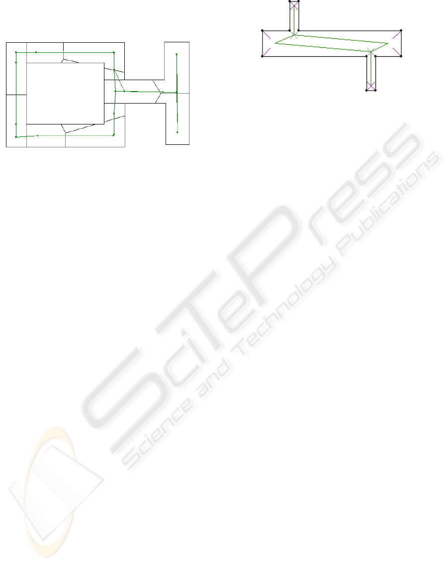
Figure 3: Example sectorization and skeleton of a simple
Map generated by the preprocessor. The skeleton includes
edges across polygons.
Note the triangle configuration of edges close to
the center of Figure 3, where a polygon without a
skeleton node had to be skipped. This is an ugly case
occurring when generating the skeletons from the ge-
ometry. It can be avoided by generating skeletons for
the sectors instead of the geometry.
Finally, landmark-based connections are created
connecting the floors on level one of the hierarchy.
The plurals in the previous sentence are intentional:
multiple sectors in a floor can have connections to
multiple sectors in another floor, represented by dis-
tinct landmarks. In fact, even a single sector can con-
tain both a staircase and an elevator. To this end,
edges on level one of the hierarchy (between distinct
floors) are assigned sets of landmarks.
When assigning sets of landmarks to the edges,
the edges are assumed to be directed (as available in
paths) to distinguish between the landmarks of the
two floors. This is done in order to accommodate
the descriptions of routes which use these landmarks,
navigating to the landmark on the floor where the user
currently is, and continuing at the landmark on the
other floor where the path resumes.
The resulting generation of the Maps, leaving out
some details discussed above, follows these steps:
1. For each zone:
(a) Compute sectorization according to Figure 2:
i. Generate Voronoi diagram of APs.
ii. Clip Voronoi regions to geometry. Resulting
sectors inherit their features from the geome-
try they are generated from.
(b) Find (and remember) shared polygon edges,
connect the sectors.
(c) Associate every AP with the containing sector.
(d) Associate those sectors who where not assigned
an AP with those APs of all direct neighbors
Figure 4: Simple polygon with bisectors and resulting
skeleton.
which where assigned an AP in the previous
step.
(e) Compute skeleton for every geometry polygon,
place resulting points in containing sector and
connect.
(f) Connect points from different geometry poly-
gons if a shared polygon edge exists (remem-
bered in step 1(b). Two candidate points are le-
gal if the line connecting the pair intersects the
polygon edge. See Figure 3.
(g) Place landmarks in the containing sectors.
Landmarks connecting zones are remembered
for connection after all zones have been gener-
ated.
2. For the landmarks remembered in step 1(g), cre-
ate the according edges between floors, and asso-
ciate all landmarks connecting those floors with
the created edge.
It remains to describe the algorithm which com-
putes the polygon skeletons. This is a novel al-
gorithm which was developed during the course of
this work, and is originally described in (Chowaw-
Liebman, 2009). The algorithms underlying idea is
based on the observation that the medial axis of the
polygon contains the lines bisecting the convex cor-
ners of the polygon, and that a node exists where two
of these lines meet.
The approximation of the medial axis computed
by this skeletonization algorithm computes bisectors
for all vertices of the polygon. These bisectors are
then clipped to the polygon, and intersections be-
tween these bisectors are computed to create the
nodes of the skeleton. Every bisector is assigned the
closest point of intersection it caused (bisectors can
intersect multiple others).
These nodes are connected by traversing the poly-
gon contour: the bisectors associate nodes of the con-
tour with one skeleton node (the closest one kept in
above paragraph), which are simply connected in or-
der of traversal along the contour. Figure 4 shows a
polygon, the bisectors of it’s contour nodes and the
resulting skeleton.
EVALUATION OF AN INDOOR NAVIGATION APPROACH BASED ON APPROXIMATE POSITIONS
199

The skeleton algorithm follows these steps:
1. Create a “contour list” of segments bisecting the
inward angles of all vertices, originating at a node
of the polygon contour and ending at the earli-
est intersection with a polygon edge (length and
polygon edges intersected are recorded). This re-
stricts the segments to lie completely inside the
polygon, according to the Jordan Curve Theorem.
This prevents intersections outside the polygon
and ensures the creation of points guaranteed to
lie inside the polygon. All bisectors are initially
marked as “intersects polygon”.
2. Find the earliest intersection between all bisect-
ing segments (again record length and other edge
intersected). The intersection kept has the lowest
length for both segments crossing. All such edges
are marked as “intersects segment”, yielding pairs
of intersecting segments.
3. All segments still marked as “intersects polygon”
are assigned an opposing node by splitting the
polygon edge at the point where the segment inter-
sects, inserting a ”bisector” pointing opposite to
the original vertex. This ”balancing” is required to
assert the correctness of the next step. Some care
must be taken during insertion to keep the contour
in a consistent ordering, e.g. counter-clockwise.
4. The ”contour list” is walked through. Every seg-
ment creates a skeleton vertex, which is connected
to the previously generated vertex (which is ini-
tialized to the last segments vertex). For segments
intersecting another segment, the vertex created is
at the intersection point determined in step 2. For
polygon intersection segments, the vertex is cre-
ated in the middle of the segment, and by exten-
sion equidistant to the closest polygon edges. Be-
cause the segments lie completely inside the poly-
gon the node is also inside.
5 TEXT GENERATION
Generation of natural language instructions is based
on the skeleton level of the hierarchy. The order of
nodes in the path defines a direction for the edges,
and with the nodes’ positions each edge defines a line
segment. Landmarks are now conveniently passed by
in the order of the closest point on the line segment.
Using parametric lines of the form ~y = ~p + x ·
~
d with
origin ~p and direction
~
d, the closest points on the line
can be expressed as a scalar value.
The line segments are constructed such that ~p is
the point of the originating node and ~p + 1 ·
~
d is the
Figure 5: Screen shots of the client in action.
point of the terminating node. That is, the line seg-
ments is defined for values of the parameter x inside
the interval [0, 1]. If the closest point on the line is
outside this intervall it is not on the line segment, and
the landmark can be discarded. Sorting the remain-
ing landmarks based on the parameter for the closest
point arranges them in order of traversal.
These edges with landmarks in order of traversal
form the basic element for text generation: instruc-
tions consider one edge after the other, with some
connectives (e.g. “and” or “then”) and landmarks for
orientation, while the skeleton takes care of corners
and intersections definition. Text generation is based
on three functions:
traverseBy instructs the user to follow the com-
plete skeleton edge, which is described as passing
by the last landmark along the edge. This land-
mark is used to reassure the user about being on
the right track, so it is left out if the last landmark
is too close to the beginning of the edge.
traverseTo describes movement to a landmark
somewhere along the edge. This is used for the
last edge of the path, along which the target land-
mark is located, a distance which is communi-
cated to the user in approximate terms, see below.
The side on which the landmark should be is also
used in the description.
rotateToward turn to face along the next edge.
This function is responsible for describing the ac-
tion needed at an intersection or corridor.
Directions and distances are discretized into a few
approximate phrases like ”to your left”, ”ahead” or
WINSYS 2010 - International Conference on Wireless Information Networks and Systems
200

”close by”, ”in the middle” and ”at the far end” to
give a few representative examples. These discretiza-
tions provide relative information which is expected
to be of more use to people than precise distances.
The difference is that ”in 68 meters” can mean the
same as ”halfway down the corridor”, the latter being
of better utility as long as users are not equipped with
odometers.
The prototype text generator simply uses
traverseBy followed by rotateToward for every
skeleton edge of the path, except for the last which
is handled by traverseTo. These functions are
implemented based on the ”fill the blanks” approach,
generating sentences of a fixed structure with the
appropriate landmark, geometry type (e.g. corridor or
room) and direction placed in their positions. Figure
5 shows a screen shot of the client software, showing
a route and the generated NLI.
6 CONCLUSIONS
A novel indoor navigation system adapted to the de-
vice whispering technique was presented. The cen-
tral element of the system is the Map data structure,
which was presented and it’s applicability to natural
language instruction generation was shown, see Fig-
ure 5. Tests of the prototype system uncovered that
common WLAN interface cards (i.e. hardware de-
vices) do not modulate transmission power when in-
structed to do so: all access points which are detected
already respond to the lowest power request. Pending
further inquiry, we are currently assuming that trans-
mission power modulation is not implemented, possi-
bly to reduce the chip’s area.
The implemented text generation system produces
NLI which are quite satisfactory, especially concern-
ing its minimalistic simplicity. In both cases, out-
put and generation complexity, the system compares
favourably with CORAL: the generated text is not
quite as eloquent, but is generated with much less ef-
fort. This indicates that our approach of skeletons an-
notated with landmarks provides adequate informa-
tion for the NLI generator.
The very simple approach to text generation
leaves open many possibilities for extension, e.g.
adding more rules to improve both the natural lan-
guage as well as for selecting landmarks to use in the
text.
REFERENCES
Aurenhammer, F. (1991). Voronoi diagrams: A survey of a
fundamental geometric data structure. ACM Comput-
ing Surveys, 23:345–405.
Aurenhammer, F. and Klein, R. (2000). Voronoi diagrams.
In Handbook of Computational Geometry, pages 201–
290. Elsevier Science Publishers B.V. North-Holland.
Chowaw-Liebman, O. (2009). Context-Sensitive Informa-
tion Systems in Wireless Networks. Master’s thesis,
RWTH Aachen University.
Chowaw-Liebman, O., Krempels, K.-H., von St
¨
ulpnagel,
J., and Terwelp, C. (2009). Indoor navigation using
approximate positions. In (Obaidat and Caldeirinha,
2009), pages 168–171.
Dale, R., Geldorf, S., and Prost, J.-P. (2003). CORAL:
Using Natural Language Generation for Navigational
Assistance. In Conferences in Research and Practice
in Information Technology, Vol. 16.
Fortune, S. (1986). A sweepline algorithm for voronoi dia-
grams. In SCG 1986: Proceedings of the second an-
nual symposium on Computational geometry, pages
313–322. ACM Press.
Krempels, K.-H., Patzak, S., von St
¨
ulpnagel, J., and Ter-
welp, C. (2009). Evaluation of directory-less wlan
positioning by device whispering. In (Obaidat and
Caldeirinha, 2009), pages 139–144.
Obaidat, M. S. and Caldeirinha, R. F. S., editors (2009).
WINSYS 2009 - Proceedings of the International Con-
ference on Wireless Information Networks and Sys-
tems, Milan, Italy, July 7-10, 2009, WINSYS is part
of ICETE - The International Joint Conference on e-
Business and Telecommunications. INSTICC Press.
Ohlbach, H., Rosner, M., Lorenz, B., and Stoffel, E.-
P. (2006). NL Navigation Commands from Indoor
WLAN Fingerprinting position data. Technical report,
REWERSE.
Schilit, B. N., Adams, N., and Want, R. (1994). Context-
Aware Computing Applications.
Wallbaum, M. and Spaniol, O. (2006). Indoor position-
ing usingwireless local area networks. John Vincent
Atanasoff Modern Computing, International Sympo-
sium on, 0:17–26.
Weiler, K. and Atherton, P. (1977). Hidden surface removal
using polygon area sorting. In SIGGRAPH ’77: Pro-
ceedings of the 4th annual conference on Computer
graphics and interactive techniques.
EVALUATION OF AN INDOOR NAVIGATION APPROACH BASED ON APPROXIMATE POSITIONS
201
