
A BUSINESS USE CASE DRIVEN METHODOLOGY
A Step Forward
Gaetanino Paolone, Paolino Di Felice, Gianluca Liguori, Gabriele Cestra and Eliseo Clementini
Department of Electrical and Information Engineering, Università degli Studi dell'Aquila
Via G. Gronchi - Nucleo Industriale di Pile, 20, L'Aquila, Italy
Keywords: Use Case, Business Modeling, System Modeling, MDA, UML.
Abstract: The present contribution reshapes a recently proposed software methodology by giving up the top-down
philosophy being part of it, to follow a strictly model-driven engineering approach. The ultimate goal of our
research is to define a methodological proposal ensuring the continuity between business modeling, system
modeling, design, and implementation. This lays the foundations for the automatic transformation process
of the behavioral business model into a software model capable of meeting user needs.
1 INTRODUCTION
It is generally acknowledged that designing and
developing software systems is becoming
increasingly complex. Fortunately, there are
methodologies and tools to tackle this demanding
and, sometimes critical, challenge. For example, the
methodology recently proposed in (Paolone et al.,
2008a; 2008b; 2009) promotes the iterative and
incremental development of complex software
systems using a methodological framework that
supports model-driven engineering. Such a
methodology is inspired to the Rational Unified
Process (Kruchten, 2003) and it poses use cases at
center of the modeling (UML, 2010).
For an IT project to be successful, it must be as
skin-tight as possible to business reality, in such a
way corporate users can find in the application
(Zhao et al., 2007) the same modus operandi of their
own function: each actor plays within the
organization a set of "use cases" and does so
regardless of automation. Today, use cases are at the
core of modeling and developing software
applications (Zelinka, Vrani´, 2009) (Duan, 2009)
(Sukaviriya et al., 2009). The relevance of use cases
in business and system modeling is also witnessed
by papers focusing on their extraction from business
modeling represented by activity diagrams (e.g.
Štolfa, et al., 2004). More recently, the research
focus is on the automatic extraction of use cases
(e.g. Rodríguez, et al., 2008).
As a matter of fact, enterprise applications are
characterized by quite complex interactions among
different use cases and within the same use case as
well. The methodology appeared in (Paolone et al.,
2009) is an instance of the proposal that empower to
manage such a complexity through a layer of classes
dedicated to use case automation.
As pointed out in (Paolone et al., 2008a), the use
case construct’s strength and usefulness lies in its
existence inside the business system regardless of
automation. The designer's task is therefore to dig
and obtain software application’s use cases from
business system analysis. Similarly, the possible
actions within a use case do exist in the business
model and determine use case scenarios to be
exported to the system model. In a nutshell, the use
case, being a constituent of the business model, is
treated in (Paolone et al., 2008a) as the fundamental
ingredient for software development.
Our methodology examines the system
behavioral aspect through a top-down process (such
an approach is commonplace amidst software
development methodologies), and then proceeds by
means of stepwise refinements of the initial business
model. This strategy, although it reveals itself above
all suitable for representing the system at different
levels of abstraction, does not consent the automatic
transformation of models and, therefore, does not
adhere to a Model Driven Architecture (MDA)
approach (MDA, 2003).
The ultimate goal of our research is to define a
methodological proposal for the automatic
221
Paolone G., Di Felice P., Liguori G., Cestra G. and Clementini E. (2010).
A BUSINESS USE CASE DRIVEN METHODOLOGY - A Step Forward.
In Proceedings of the Fifth International Conference on Evaluation of Novel Approaches to Software Engineering, pages 221-226
Copyright
c
SciTePress
transformation process of the behavioral business
model into a software model that is capable of
meeting user needs (i.e., close-fitting to business
processes). To this end, we question the convenience
of using a top-down approach in favor of a full
MDA approach, ensuring thus the continuity
between business modeling, system modeling,
design, and implementation.
The next step (undertaken by this position paper)
modifies our previous approach by making it
possible to comprehend and design a software
application starting from the business system
requirements. In other words, we strive to extract
use cases from business modeling and reproduce
them in system modeling.
The article is organized as follows. Section 2
summarizes the methodology appeared in (Paolone
et al., 2008a ; 2008b; 2009). Section 3 describes
what is still missing with respect to the objective of
automatically building software systems. Section 4
sets the ground for the extension of the
methodological process of Section 2 to pursue our
goal.
2 THE METHODOLOGY
The methodology introduced in (Paolone et al., 2008
a ; 2008b; 2009) allows us to represent in detail two
models: the business and the system model. Use case
modeling and realization are the most important
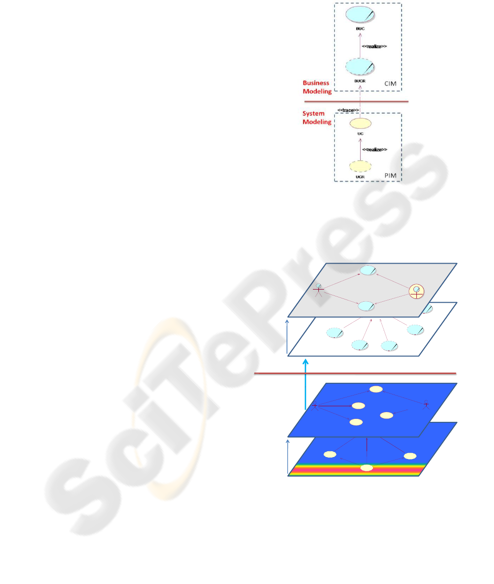
aspects of the methodology. Our proposal is
centered around four distinct layers (Figure 1) with
an iterative and incremental approach that leads to
the realization of a Business Use Case (BUC) into
the software application through stepwise
refinements.
The first two layers of use case analysis are
placed in the business modeling context: their
objective is to get a complete representation of the
given business reality. The next two layers are
instead placed in the system modeling context with
the objective of representing the software system.
More in detail, we can say that the first layer
concerns BUCs analysis, which are then specialized
by Business Use Case Realizations (BUCRs) in the
second layer. Afterwards, a trace operation is used to
define the system Use Cases (UCs) (third layer),
which are then specialized by Use Case Realizations
(UCRs) (fourth layer). The latter ones can be
implemented by a Java class.
In addition, Figure 1 shows the relationship
between the four layers with the Computation
Independent Model (CIM) and the Platform
Independent Model (PIM) widely mentioned in the
software engineering literature (MDA, 2003).
Figure 1: The methodological layers (sketch).
Figure 2 extends Figure 1 to an example
referring to a real-life document management project
for a bank, where every layer contains a type of
UML diagram.
DocumentFromBank
DocumentFromSupplier
DocumentAquisition
<<realize>>
<<realize>>
LinkFile
<<realize>>
<<extend>>
<<extend>>
Building Localization
Document Acquisition
Document Distribution
Document Filing
Document Validation
Sender
Documental Management
<<realize>>
<<realize>>
<<realize>>
<<realize>>
<<realize>>
<<realize>>
<<realize>>
<<trace>>
<<realize>>
Documental Management
Employee
(f rom Actors)
<<communicate>>
Manager
(f rom Actors)
<<communicate>>
Product Handling
<<communicate>>
<<communicate>>
Business
Modeling
System
Modeling
Person
Employee
(f rom Actors )
Enterprise
Supplier
Manager
(f rom Actors )
Internal Document Acquisition
Figure 2: The methodological layers (complete).
In the following, we provide more details about
the example. Figure 3 shows a fragment of the BUC
diagram.
ENASE 2010 - International Conference on Evaluation of Novel Approaches to Software Engineering
222
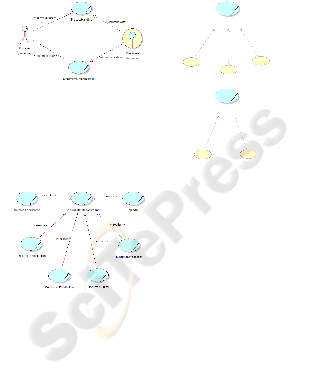
Figure 3: The BUC diagram (1
st
layer).
This example underlines that the BUC is used to
represent business areas (e.g. Documental
Management) that involve many actors, while it
should be used to express an actor/system
interaction. In this context, the BUC shows its
inadequacy. For each BUC, we define the related
BUCRs. Referring to the BUC Documental
Management, Figure 4 proposes six BUCRs:
acquisition, validation, distribution and store of the
document, in addition to the management of senders
and physical structures (Buildings) that store the
documents.
Figure 4: The BUC realize diagram (2
nd
layer).
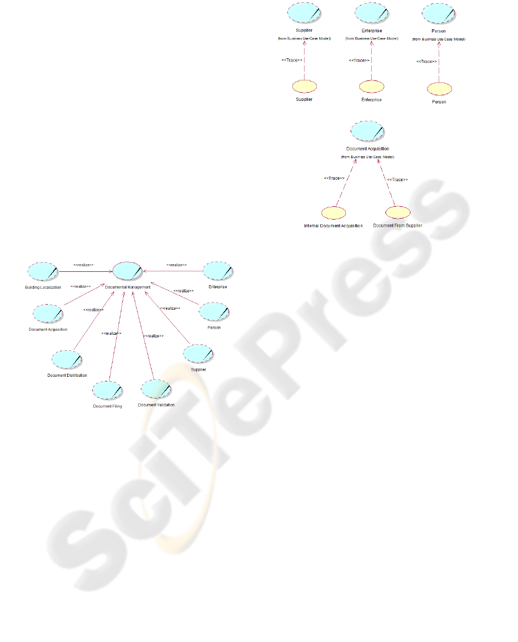
After the business modeling phase, we analyze
the part of the system that will be automated. The
“Trace” operation can introduce many system UCs
for a single BUCR. For example, in documental
management, document loading can be done by the
bank, but also by suppliers. In the same way, in the
system perspective, it is not possible to consider a
generic “Sender”, but we must manage various types
of them. (see Figure 5).
Sender
(from Business Use-Case Model)
Document Acquisition
(from Business Use-Case Model)
Supplier
Person
Enterprise
<<Trace>>
<<Trace>>
<<Trace>>
Internal Document Acquisition
Document From Supplier
<<Trace>>
<<Trace>>
Figure 5: The UC trace diagram.
The output of the trace operation produces the
system UCs of the third layer of Figure 2.
In the last phase of the subsystem behavioural
analysis, we must identify at least one system UCR
for each system UC. In this phase, we also introduce
some technological UCRs, such as “LinkFile”.
For the sake of brevity, we do not present an
example of system use case realization diagram, but
it should be straightforward to understand that this
operation introduces a further refinement of the
subsystem.
The current methodology has a strong industrial
impact because it has been repeatedly applied in real
projects with good results. Its adoption has brought
benefits both in terms of the engineering aspects of
design and development time (Paolone et al.,
2008a). The methodology enables us to build
software systems with the help of a Java-based
framework that speeds up software development.
In conclusion, we can reaffirm that the
methodological process is UC-driven, since the UC
artefact exists both in the business model and system
model, although it is represented by different
stereotypes, and is also exported to code.
A BUSINESS USE CASE DRIVEN METHODOLOGY - A Step Forward
223
3 LIMITS OF THE CURRENT
APPROACH
The current methodology has a limit from the MDA
point of view, which is caused by the application of
the top-down approach. Indeed, the top-down
approach has a degree of subjectivity regarding the
level of abstraction that is chosen at each layer and
the use case definition at business and system level.
Thus, it is perfectly possible that two designers
produce different UML diagrams to represent the
same business reality and the consequent software
system, without having the means to prove the
correctness of a solution with respect to the other.
Nevertheless, a designer could decide not to describe
in detail the representation of a business process
without this being an error.
With regard to the example of Section 2, the
business analyst could produce the diagrams of
Figure 6 and Figure 7 as a correct alternative to
Figure 4 and Figure 5.
Figure 6: An alternative BUC realize diagram (2
nd
layer).
Unfortunately, the lack of detail is not
compatible with the MDA approach. To pursue an
MDA approach, it must be possible to automatically
transform a given model into another one, by using a
finite set of values and rules that produce a unique
result.
In a methodological approach that works with
stepwise refinements through four distinct layers, it
is unlikely that a set of rules could be identified
allowing a unique model transformation. In fact, the
latter burden is often left to the skills and cleverness
of the business analyst and software designer. This is
the main cause of the already mentioned subjectivity
in the methodology, which consequently loses
formal soundness.
Figure 7: An alternative UC trace diagram.
The limit of the current methodology concerns
the system behavioural aspect (use case model) and
not the structural aspect (class diagrams).
In fact, in the class model defined in the system
modeling phase, we can find all the business object
classes discovered during the business modeling
phase and that during the trace operation (the
passage from business modeling to system
modeling) have been tagged as necessary for system
automation: the same classes are also present in the
coded model.
During an automatic transformation process, it is
possible for the structural aspect of the system to
uniquely identify the object classes that need to be
created starting from the business model. This is not
possible for the behavioural aspect, where the
continuous refinement process does not consent the
identification of rules for a unique mapping.
4 THE APPROACH
WE LOOK AT
The design of a large enterprise application is a
complex process, since it represents the automation
of the enterprise system. The most delicate part of
this process is the identification of the UCs, which
express the interactions between end-users and
system according to usual enterprise workflows and
establishing the communication between all
stakeholders.
ENASE 2010 - International Conference on Evaluation of Novel Approaches to Software Engineering
224
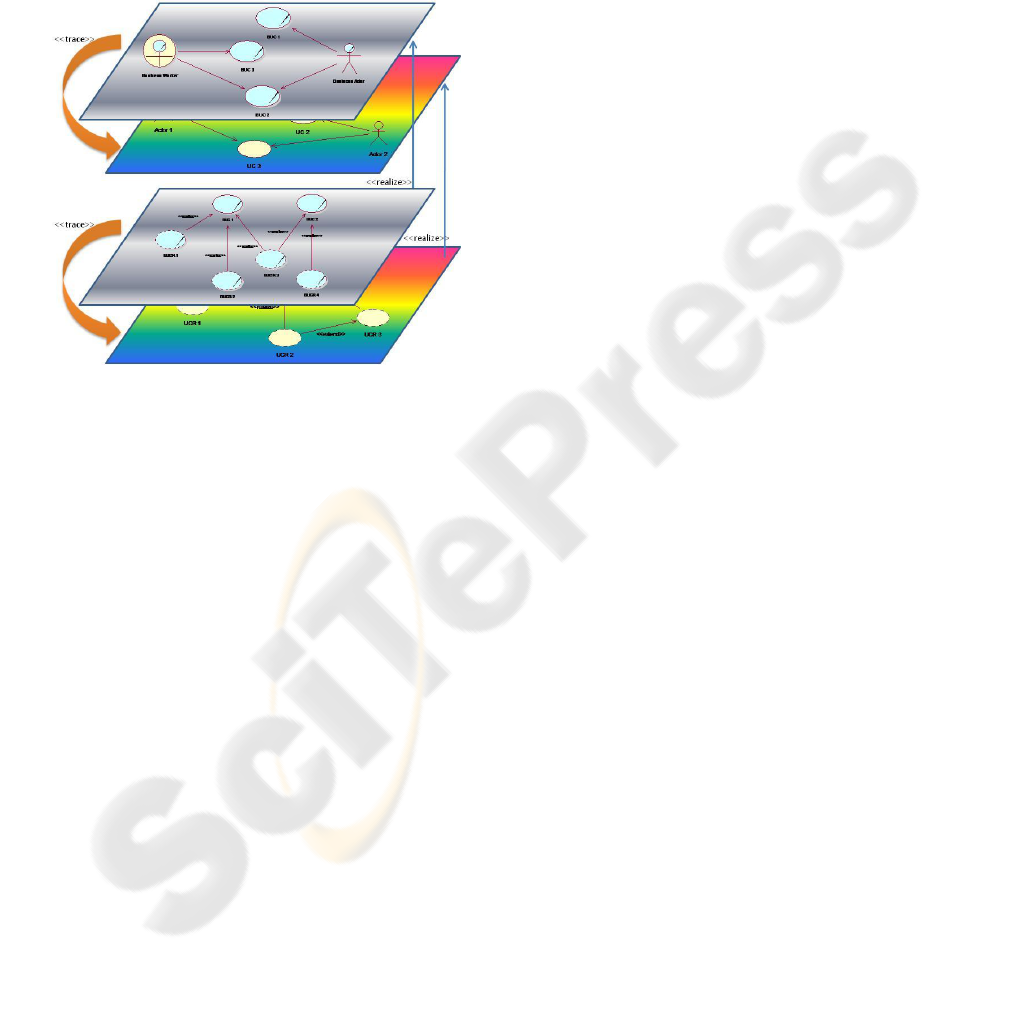
The solution we are developing (Figure 8) starts
as in (Paolone et al., 2008a) with business analysis,
distinguished between BUC modeling and business
analysis modeling: business modeling layers remain
the same with a realization process that connects
them. Instead, during the system analysis phase, we
introduce a trace operation of both business
modeling layers into the two system modeling
layers.
Figure 8: The methodological layers (re-arranged).
In this way, we can reproduce all the BUCs and
BUCRs in the system perspective, becoming UCs
and UCRs. The purpose of the trace operation
remains the same, in the sense that we transfer to
system modeling the only UCs that need to be
automated.
Working this way, the methodological process
would become the bridge between business
requisites and the software solution to be developed.
This would allow a breakthrough in system
engineering: different workgroups (with the same
skills) would produce identical system models for
enterprise automation.
Since BUCs exist in the enterprise system
independently from its level of automation, the
BUCs scenarios would be exported without changes
to the system model. Therefore, we believe that the
proposed methodology could create a solid
foundation for model-driven processes, allowing to
set exact rules for model transformations.
We achieve this result because we substitute the
refinement process with a trace process. Having a
complete correspondence between business and
system models, mapped only by the “trace”
operation and not contaminated by stepwise
refinements, should assure the complete
correspondence between business system and
software system, both in behavioural and structural
aspects.
This approach needs the specification of a high
degree of detail during BUCs discovery phase. This
somehow prevents the designer from taking
advantages of the top-down approach, which
normally helps to reason at a high level of
abstraction during business modeling and this is
sometimes a desirable feature in the first steps of
conceptual modeling. Nevertheless, with the
proposed approach we can have the great advantage
of defining exact transformation rules from BUCs to
software system.
The approach still considers the subdivision of
the enterprise in subsystems that are represented by
an appropriate number of UML diagrams (Paolone
et al., 2008a) (UML, 2010), correctly managing the
system behavioural complexity. In the same way, it
continues to represent the system model with UML
diagrams. The main difference of the proposed
approach lies in the relationship occurring between
business models and system models.
While our methodology is still at a draft stage, it
is oriented to the solution of concrete problems
related to UC management. In fact, the UC is a set of
scenarios and actions (UML, 2010). For every
BUCR it is possible to define business actions in the
context of a scenario. The system UCs instantiation,
their navigation, and the management of their
lifecycle would become the services offered by the
computerized system, along with the representation
of UC inclusion and extension, as they are defined in
the business model.
Obviously, the methodology needs to be
validated first of all in the current methodological
context and, then “on the field” through the
development of real enterprise software projects.
The validation task involves many aspects related to
the application of the UML, in a process aimed to
obtain seamless continuity between business and
software models. For example, there are issues
related to the representation of scenarios and actions,
defined in the business model, that will have to find
a correspondence in the code to correctly model use
cases and satisfy end-user needs.
REFERENCES
Zelinka, L., Vrani´, V., 2009. A Configurable UML Based
Use Case Modeling Metamodel. First IEEE Eastern
European Conference on the Engineering of Computer
Based Systems.
A BUSINESS USE CASE DRIVEN METHODOLOGY - A Step Forward
225

Duan, J., 2009. An approach for modeling business
application using refined use case. ISECS
International Colloquium on Computing,
Communication, Control, and Management (CCCM
2009).
Sukaviriya, N., Mani, S., Vibha Sinha, V., 2009.
Reflection of a Year Long Model-Driven Business and
UI Modelling Development. INTERACT 2009, Part II,
LNCS 5727, pp. 749–762.
Paolone, G., Clementini, E., Liguori, G., 2008a. A
methodology for building enterprise Web 2.0
Applications. The Modern Information Technology in
the Innovation Processes of the Industrial Enterprises
Prague Czech Republic, 12-14 November 2008.
Paolone, G., Clementini, E., Liguori, G., 2008b. Design
and Development of web 2.0 Applications. itAIS 2008
Paris France, 13-14 December 2008.
Paolone, G., Clementini, E., Liguori, G., Cestra, G., 2009.
Web 2.0 Applications: model-driven tools and design.
itAIS 2009 Costa Smeralda (Italy) October 2-3, 2009.
UML, Unified Modeling Language, 2010. Version 2.1.2,
http://www.uml.org/
Zhao, X., Zou, Y., Hawkins, J., Madapusi, B., 2007. A
Business Process Driven Approach for Generating E-
Commerce User Interfaces. Model Conference 2007
Nashville TN September 30 – October 5 2007, pp.
256-270.
P. Kruchten, 2003. Rational Unified Process, An
Introduction. Second Edition”. UK, Addison Wesley.
MDA, Model Driven Architecture, 2003. Object
Management Group: MDA Guide Version 1.0.1,
http://www.omg.org/docs/omg/03-06-01.pdf
Štolfa, S., Vondrák, I., 2004. A Description of Business
Process Modeling as a Tool for Definition of
Requirements Specification. 12th System Integration
2004. pp 463 469.
Rodríguez, A.; Fernández-Medina, E; Piattini, M. 2008.
Towards Obtaining Analysis-Level Class and Use
Case Diagrams from Business Process Models. ER
Workshops 2008.
ENASE 2010 - International Conference on Evaluation of Novel Approaches to Software Engineering
226
