
Platform Independent Model Development by Means of
Topological Class Diagrams
1
Janis Osis and Uldis Donins
Department of Applied Computer Science, Institute of Applied Computer Systems
Riga Technical University, Meza iela 1/3, LV 1048, Riga, Latvia
Abstract. Transformation from model to model takes significant place in Mod-
el Driven Architecture (MDA). Model Driven Architecture considers system
from three viewpoints: computation independent, platform independent, and
platform specific. Despite the fact that each viewpoint has its own representing
model, the transformation between computation independent model (CIM) and
platform independent model (PIM) is fuzzy. In this paper is proposed topology
oriented approach for CIM to PIM transformation and PIM representation. To-
pology used within this approach is borrowed from Topological Functioning
Model (TFM). TFM uses mathematical foundations that holistically represent
complete functionality of the problem and application domains and therefore
can be used as CIM and as a source for transforming CIM to PIM. Application
of TFM within software development process enables formal analysis of busi-
ness system and formal designing of system structure. Software development
begins with TFM creation. After construction of business system’s TFM by ap-
plying transformation on TFM a system structure representing PIM is defined.
As a basis for system structure definition is used topological class diagram. To-
pological class diagram is combination of Unified Modeling Language (UML)
class diagram and topology borrowed from TFM.
1 Introduction
Model Driven Architecture (MDA) [4] considers system from three viewpoints: com-
putation independent, platform independent, and platform specific. For each view-
point there are defined corresponding model: Computation Independent Model (CIM)
which represents system requirements and shows the way in which the business sys-
tem works within the real environment without delving into details of system’s struc-
ture and software application implementation; a Platform Independent Model (PIM)
which designs system at abstraction level who makes it possible to use this model
with different platforms of similar type; a Platform Specific Model (PSM) provides a
set of technical concepts, representing different kinds of parts that make up a platform
and its services to be used by an application, and, hence, does change transferring
system functioning from one platform to another.
1
This work has been supported by the European Social Fund within the project, Support for the imple-
mentation of doctoral studies at Riga Technical University”.
Osis J. and Donins U. (2010).
Platform Independent Model Development by Means of Topological Class Diagrams.
In Proceedings of the 2nd International Workshop on Model-Driven Architecture and Modeling Theory-Driven Development, pages 13-22
DOI: 10.5220/0003042500130022
Copyright
c
SciTePress

The conception of the MDA supports abstraction and refinement in models [3, 4].
Models can be described in any modeling language defined in accordance with the
MDA Foundation Model [5]. Models are obtained by transformations: PIM-to-PIM,
PIM-to-PSM, PSM-to-PSM, and PSM-to-PIM. Despite the fact that software devel-
opment within MDA life cycle [14] begins with creation of business system’s CIM
and that Transformation from model to model takes significant place in MDA, the
transformation CIM-to-PIM is not even included in MDA specification. Reason of
this might be that there is an opinion that requirements modeled in CIM often lack a
good structure and therefore it is not possible to automate the CIM-to-PIM transfor-
mation [14]. Lack of traceability within the CIM and lack of transformation from the
computation independent viewpoint to the platform independent viewpoint leads in
manual CIM-to-PIM conversion which depends much on designers’ personal expe-
rience and knowledge and therefore the quality of PIM can not be well controlled [10,
15].
The structure quality of CIM can be improved by using Topological Functioning
Model (TFM) [9] as model to represent the CIM [10]. TFM has strong mathematical
basis and is represented in a form of a topological space (X, Θ), where X is a finite
set of functional features of the system under consideration, and Θ is the topology
that satisfies axioms of topological structures and is represented in a form of a di-
rected graph. The necessary condition for constructing topological space is a mea-
ningful and exhaustive verbal, graphical, or mathematical system description. The
adequacy of a model describing the functioning of a concrete system can be achieved
by analyzing mathematical and functional properties of such abstract object. A TFM
has topological characteristics: connectedness, closure, neighborhood, and continuous
mapping.
Despite that any graph is included into combinatorial topology, not every graph is
a topological functioning model. A directed graph becomes the TFM only when subs-
tantiation of functioning is added to the above mathematical substantiation. The latter
is represented by functional characteristics: cause-effect relations, cycle structure, and
inputs and outputs [9]. It is acknowledged that every business and technical system is
a subsystem of the environment. Besides that a common thing for all system (technic-
al, business, or biological) functioning should be the main feedback, visualization of
which is an oriented cycle. Therefore, it is stated that at least one directed closed loop
must be present in every topological model of system functioning. It shows the
“main” functionality that has a vital importance in the system’s life. Usually it is even
an expanded hierarchy of cycles. Therefore, a proper cycle analysis is necessary in
the TFM construction, because it enables careful analysis of system’s operation and
communication with the environment. [11]
The main idea of the given work is to provide a way to do formal transformation of
CIM-to-PIM, to represent PIM in more formal form by using topological class dia-
gram [8], and to present proposal for UML profile for topological class diagram. A
topological class diagram is a new type of Unified Modeling Language (UML) [12]
class diagram [13]. In this type of class diagram is combined together UML class
diagram and topology borrowed from TFM.
This paper is organized as follows: Section 2 describes the PIM development by
means of topological class diagram; Section 3 gives an example of applaying
topological class diagram for CIM-to-PIM transformation and PIM development;
14

Section 4 presents proposal for UML profile for topological class diagrams and
describes key constructs of proposed UML profile; and Section 5 gives conclusions
of this research and discuss future work.
2 PIM Development by Means of Topological Class Diagram
PIM development by means of topological class diagram begins with creation of
TFM of system functioning. Schematic representation of PIM development by means
of topological class diagram is given in Fig. 1.
Within previous researches there are stated three steps for developing TFM of sys-
tem functioning [10, 11]:
Step 1: Definition of physical or business functional characteristics
, which consists of
the following activities: 1) definition of objects and their properties from the problem
domain description; 2) identification of external systems and partially-dependent
systems; and 3) definition of functional features using verb analysis in the problem
domain description, i.e., by finding meaningful verbs.
Step 2: Introduction of topology
Θ
(in other words – creation of topological space),
which means establishing cause and effect relations between functional features.
Cause-and-effect relations are represented as arcs of a directed graph that are oriented
from a cause vertex to an effect vertex. Topological space Z is a system represented
by Equation (1),
Z = N
∪
M
(1)
where N is a set of inner system functional features and M is a set of functional
features of other systems that interact with the system or of the system itself, which
affect the external ones.
Step 3: Separation of the topological functioning model
from the topological space of
a problem domain, which is performed by applying the closure operation over a set of
system’s inner functional features (the set N) as it is shown by Equation (2),
[]
U
n
XNX
1=
==
η
η
(2)
where Xη is an adherence point of the set N and capacity of X is the number n of
adherence points of N. An adherence point of the set N is a point, whose each neigh-
borhood includes at least one point from the set N. The neighborhood of a vertex x in
a directed graph is the set of all vertices adjacent to x and the vertex x itself. It is
assumed here that all vertices adjacent to x lie at the distance d=1 from x on ends of
output arcs from x.
Construction of TFM can be iterative. Iterations are needed if the information col-
lected for TFM development is incomplete or inconsistent or there have been intro-
duced changes in system functioning or in software requirements.
After construction of TFM it is possible to transform topology defined in TFM into
class diagrams. It is possible to transform topology from TFM into class diagrams
because TFM has strong mathematical basis. In this way it means that between
classes are precisely defined relations which are identified from the problem domain.
15
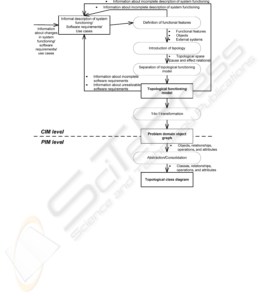
In traditional software development relations (mostly associations and generaliza-
tions) between classes are defined by the designer’s discretion. [8].
Fig. 1. PIM development by means of topological class diagram.
In order to develop a topological class diagram, after the creation of TFM a graph of
problem domain objects must be developed and afterwards transformed into a topo-
logical class diagram. In order to create problem domain object graph, it is necessary
to detail each functional feature of the TFM to a level where it uses only one type of
objects. After construction of problem domain object graph all the vertices with the
same type of objects and operations must be merged, while keeping all relations with
other graph vertices. As a result, topological class diagram with attributes, operations
and topological relationships is defined.
3 Case Study
For a better understanding of PIM development by means of topological class
16

diagram (the construction of the TFM and development of the topological class dia-
gram) a small fragment of an informal description from the project, in which a laun-
dry system is developed, is used. Following subsections give informal description of
laundry business system functioning and shows how to develop PIM basing on given
description.
3.1 Informal Description of Laundry Business System Functioning
When a person arrives at laundry he gets checked by clerk. All laundry clients are
registered. Registration is done by the clerk. Any person, who is registered in the
laundry client register and who has filled out client card is considered as a client. If
the person is not a registered client yet, the clerk performs the client registration. If
the client does not have the client card yet or has lost his client card, the clerk makes
it anew. The client card bears the information about the client (name, surname and
address) and every client card has its own unique identification number. Registered
clients with client card have the right to use the services provided by laundry.
If a client wants to give linen for washing at laundry, he requests the linen registra-
tion form from clerk. After creation of linen registration form, client gives linen to
clerk. Clerk then weights received linen and registers linen weight into registration
form. When weight of linen is registered clerk gives out linen registration form to the
client. Client then fills out all necessary data (linen type, requirements for washing,
due date). After client has filled out linen registration form, he gives it back to clerk.
Clerk checks if it is possible to wash linen till given due date. If it is not possible to
fulfill washing till requested due date, clerk checks for nearest possible due date,
announce it to client and gives back linen registration form to client for filling out
new due date. Client writes down new due date and returns linen registration form
back to clerk. If it is possible to fulfill washing till requested due date, clerk calculates
price of the new order and notifies the customer. If the price is acceptable for client,
clerk registers linen registration form and assigns unique identification number to the
order. Clerk prepares receipt of the received order by filling out order unique identifi-
cation number, due date, price and weight of the linen and gives it out to client.
Received laundry orders are registered in the orders list. After registering new or-
der into order list it is sorted to determine whether the order can be fulfilled by using
laundry’s washing machines. The order is passed for collaboration partner if dry-
cleaning is needed. To pass the order to collaboration partner a purchase order is
created by clerk. Clerk assigns a number to purchase order and fills out purchase
order with necessary data (linen type and weight, requirements for washing, due date,
order unique identification number). Purchase order number is registered in linen
registration form by clerk. After purchase order is prepared, the linen gets transferred
to collaboration partner for washing. When collaboration partner returns washed
linen, clerk makes a mark in linen registration form that linen is received from colla-
boration partner and is ready for giving back to client. If linen is washed by using one
of laundry’s washing machines, clerk makes a mark in linen registration form in
which machine linen was washed and that linen is ready for giving back to client.
After completing an order it is took out from the orders list.
17

If client wants to take back washed linen, he provides receipt to clerk. After receiv-
ing receipt clerk checks the order list whether or not the order has been fulfilled and
whether the client can get back linen. If the order is fulfilled clerk prepares invoice of
provided service and issues it to client. After client has paid the invoice, clerk gives
the linen to client and makes a mark in linen registration form that linen has been
given back to client.
3.2 Functional Features
Functional features of system functioning are defined in a form of tuple. Within this
research extended version of functional feature tuple is used. Extended version is
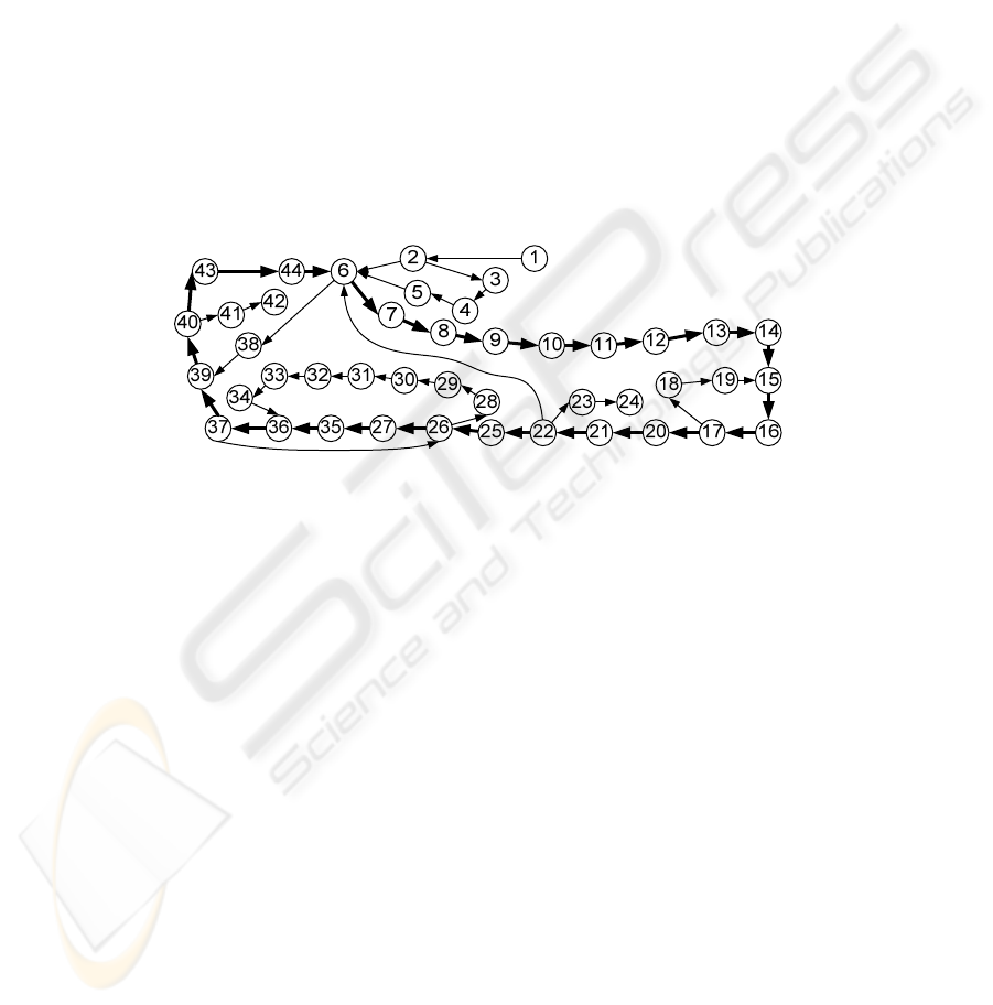
defined in [8]. For the laundry project example has been defined 44 functional fea-
tures (in the form of tuple containing the following parameters: identificator, object
action (A), precondition (PrCond), object (O), mark if functional feature is external or
internal), where C denotes Clerk, Cl – Client, In – Inner, and Ex - External:
<1, A person arriving at laundry, Ø, Person, Ex>, <2, Checking of personal data
with the laundry’s client register, Ø, C, In>, <3, Registering client in the laundry
clients’ register, if the person is not registered in the clients’ register yet, C, In>, <4,
Preparing of client card, if the person does not have the client card yet (or) if the
client has lost his client card, C, In>, <5, Client card issue to the client, Ø, C, In>, <6,
Authorizing client status, if the person is registered (and) if the client has the client
card, C, In>, <7; Requesting linen registration form; If client has client card; Cl; In>,
<8; Creating linen registration form; Ø; C; In>, <9; Giving linen to clerk; Ø; Cl; In>,
<10; Taking linen from client; Ø; C; In>, <11; Weighting received linen; Ø; C; In>,
<12; Registering linen weight in linen registration form; Ø; C; In>, <13; Giving out
linen registration form to client; Ø; C; In>, <14; Filling out linen registration form
(linen type, requirements for washing); Ø; Cl; In>, <15; Filling out order due date in
linen registration form; Ø; Cl; In>, <16; Giving back linen registration form to clerk;
If linen registration form is filled out; Cl; In>, <17; Checking due date; Ø; C; In>,
<18; Giving back linen registration form to client; If it is not possible to fulfill wash-
ing till requested due date; C; In>, <19; Announcing nearest possible due date to
client; Ø; C; In>, <20; Calculating price of the new order; Ø; C; In>, <21; Registering
linen registration form; If price is acceptable for client; C; In>, <22; Assigning unique
identification number to the order; Ø; C; In>, <23; Preparing receipt of the received
order by filling out order unique identification number, due date, price and weight of
the linen; Ø; C; In>, <24; Giving out receipt to client; Ø; C; In>, <25; Registering
order in laundry orders’ list; Ø; C; In>, <26; Sorting order list; Ø; C; In>, <27; Fulfil-
ling order by using laundry’s washing machines; If order can be fulfilled by using
laundry’s washing machines; C; In>, <28; Creating purchase order; If dry-cleaning is
needed; C; In>, <29; Assigning purchase order number to purchase order; Ø; C; In>,
<30; Filling out purchase order (linen type and weight, requirements for washing, due
date, order unique identification number); Ø; In>, <31; Registering purchase order
number in linen registration form; Ø; C; In>, <32; Transferring linen to collaboration
partner; Ø; C; In>, <33; Receiving linen from collaboration partner; Ø; C; In>, <34;
Marking in linen registration form that linen is received from collaboration partner;
Ø; C; In>, <35; Marking in linen registration form in which machine linen was
18
washed; Ø; C; In>, <36; Marking in linen registration form that linen is ready for
giving back to client; Ø; C; In>, <37; Taking out completed order from the orders list;
Ø; C; In>, <38; Providing receipt to clerk; If client wants to take back washed linen;
Cl; In>, <39; Checking the order list whether or not the order has been fulfilled; Ø; C;
In>, <40; Preparing invoice of provided service; If the order is fulfilled; C; In>, <41;
Issuing invoice to client; Ø; C; In>, <42; Paying for received service according to
invoice; Ø; Cl; Ex>, <43; Giving out linen to client; If the invoice is paid; C; In>,
<44; Marking in linen registration form that linen has been issued to client; Ø; C; In>.
3.3 CIM of Laundry Business System
CIM of Laundry business system is represented by the means of TFM. Definition of
TFM is done according to steps described in 2
nd
section. Cause-and-effect relations
are represented as arcs of a directed graph that are oriented from a cause vertex to an
effect vertex. The identified cause-and-effect relations between the functional fea-
tures are illustrated by the means of the topological space (see Fig. 2).
Fig. 2. Topological space of the laundry functioning.
In the Fig. 2 is clearly visible that cause-and-effect relations form functioning
cycles. All cycles and sub-cycles should be carefully analyzed in order to completely
identify existing functionality of the system. The main cycle (cycles) of system func-
tioning (i.e., functionality that is vital for the system’s life) must be found and ana-
lyzed before starting further analysis [10].
3.4 PIM of Laundry Business System by Means of Topological Class Diagram
Before development of PIM (topological class diagram) of laundry system it is
needed to construct problem domain object graph. After construction of problem
domain objects graph it is possible to develop PIM (see Fig. 1) by applying transfor-
mation on developed problem domain objects graph. Due to the space limitations the
process of developing objects graph in detail and an example of this graph can be
seen in [1] and [8]. The developed topological class diagram of laundry system can be
seen in Fig. 3 (notation used for representing topological relationships within this
article is the same as for associations in UML [2]). Defined attributes and operations
are obtained during TFM transformation to problem domain objects graph.
19
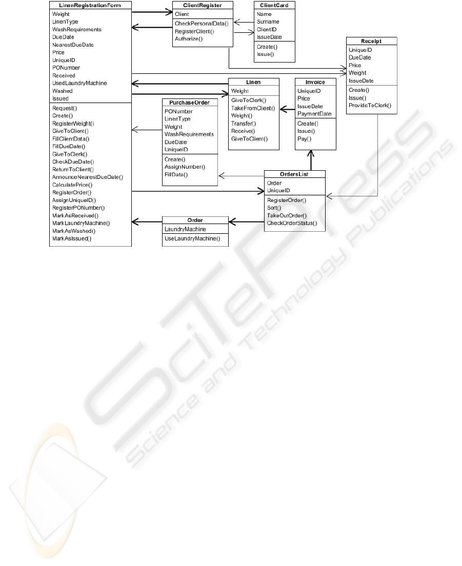
Fig. 3. Topological class diagram of laundry system.
With the boldest lines in developed topological class diagram is maintained main
functional cycle which is defined by the expert within the constructed TFM. This
reflects the idea proposed in [9] and [11] that the holistic domain representation by
the means of the TFM enables identification of all necessary domain concepts and,
even, enables to define their necessity for a successful implementation of the system.
4 UML Profile Proposal for Topological Class Diagrams
In this section is given proposal of UML profile for topological UML (TopUML).
The idea of Topological class diagram is considered as part of TopUML. Idea of
topological UML diagrams (including topological UML class diagrams) is adapted
from [9]. Metamodel of topological class diagram is defined in accordance with [5]
(metamodel is described in terms of OMG Meta-Object Facility (MOF)). Fig. 4.
shows that the metamodel of topological class diagram is placed at metalevel M2.
The metamodel represents the topological class diagram as an instance of the me-
taclass TopologicalClassDiagram that includes at least one class of metaclass Topo-
logicalClass, two operations of metaclass TopologicalOperation and at least one
cycle which is instance of metaclass TopologicalCycle. Each cycle contains at least
two topological relationships of metaclass TopologicalRelationship. Each topological
relationship is connected with two operations – one operation forms cause of the
relationship but the other one – effect of topological relationship.
20
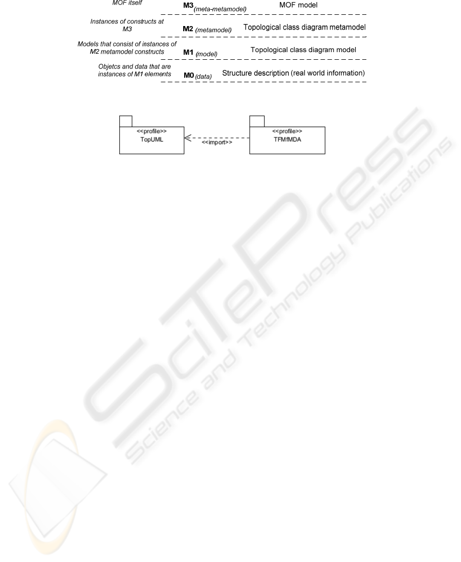
Fig. 4. MOF Metamodel levels and Topological class diagram within them.
Fig. 5. UML profile for TopUML.
Each instance of metaclass TopologicalOperation contains one functional feature
which is instance of metaclass TFMFunctionalFeature. In fact, instances of metaclass
TopologicalOperation are defined by applying transformation on Topological func-
tioning model (relation one to one between instance of TFMFunctionalFeature and
instance of TopologicalOperation is obtained from this transformation in which TFM
is transformed into topological class diagram). Metaclass TFMFunctionalFeature is
stereotype which is defined within UML profile for TFMfMDA [10]. Metamodel of
topological class diagram itself is an extension of class diagrams defined in [6] and
[7]. The UML profile proposal for TopUML is given in Fig. 5.
5 Conclusions and Future Work
By using TFM within MDA software development life cycle it is possible to
represent CIM with TFM and to improve the structure quality of CIM. This can be
achieved because TFM has strong mathematical basis. The next acquisition is topolo-
gy defined with the help of TFM. It is possible to transform topology defined in TFM
into UML diagrams. By transforming topology from TFM to UML class diagram it is
possible to do formal transformation of CIM-to-PIM and reflect PIM with more for-
mal model – topological class diagram. In this way the formalism of class diagrams
means that between classes now are precisely defined relationships which are identi-
fied from the problem domain with help of TFM. In traditional software development
scenario relations (mostly associations and generalizations) between classes are de-
fined by the modeler’s discretion. In this paper is described approach of CIM devel-
opment by means of TFM and PIM development by means of topological class dia-
grams. Right after description of mentioned approach there are given small example
of software development for laundry business system.
To formally describe topological class diagrams within this paper is proposed a
new UML profile – TopUML, which combines together UML diagrams and formal
basis of topological modeling.
21

Future research directions are as follows: study possibilities for introducing topol-
ogy and in this way to increase formalization level of other UML diagrams; develop
full specification of TopUML profile; and develop a tool that supports TopUML
within software development process.
References
1. Donins, U.: Software Development with the Emphasis on Topology. Advances in Data-
bases and Information Systems. Lecture Notes in Computer Science, Vol. 5968. Springer-
Verlag Berlin Heidelberg New York (2010) 220-228
2. Fowler, M.: UML Distilled: A Brief Guide to the Standard Object Modeling Language, 3
rd
ed. Addison-Wesley (2003)
3. Mellor, S., Balcer, M.: Executable UML: A Foundation for Model-Driven Architecture.
Addison-Wesley (2002)
4. Miller, J., Mukerji, J. (eds): OMG: MDA Guide Version 1.0.1 (2003)
5. OMG: A Proposal for an MDA Foundation Model, V00-02 (2005)
6. OMG: Unified Modeling Language Infrastructure Specification, version 2.1.2 (2007)
7. OMG: Unified Modeling Language Superstructure Specification, version 2.1.2 (2007)
8. Osis J., Donins U.: An Innovative Model Driven Formalization of the Class Diagrams.
Proceedings of 4th International Conference on Evaluation of Novel Approaches to Soft-
ware Engineering (ENASE 2009), Milano, Italy, pp. 134-145 (2009)
9. Osis J.: Extension of Software Development Process for Mechatronic and Embedded Sys-
tems, Proceeding of the 32
nd
International Conference on Computer and Industrial Engi-
neering, University of Limerick, Limerick, Ireland, pp. 305-310 (2003)
10. Osis, J., Asnina, E.: Enterprise Modeling for Information System Development within
MDA. In: Proceedings of the 41
st
Annual Hawaii International Conference on System
Sciences (HICSS 2008), USA, p. 490 (2008)
11. Osis, J.: Formal Computation Independent Model within the MDA Life Cycle, Internation-
al Transactions on Systems Science and Applications, Vol. 1, No. 2, pp. 159 – 166 (2006)
12. Rumbaugh, J., Jacobson, I., & Booch, G.: The Unified Modeling Language Reference
Manual, 2nd ed. Addison-Wesley (2004)
13. Rumbaugh, J., Jacobson, I., & Booch, G.: The Unified Modeling Language User Guide,
2nd ed. Addison-Wesley (2005)
14. Warmer, J., & Kleppe, A.: The Object Constraint Language: Getting Your Models Ready
for MDA, 2
nd
ed. Addison-Wesley (2003)
15. Zhang W., Mei H., Zhao H., Yang J.: Transformation from CIM to PIM: A Feature-
Oriented Component-Based Approach. Model Driven Engineering Languages and Systems.
Lecture Notes in Computer Science, Vol. 3713. Springer-Verlag Berlin Heidelberg New
York (2005) 248-263
22
