
Transforming Textual Use Cases to a Computation
Independent Model
1
Jānis Osis and Armands Šlihte
Faculty of Computer Science and Information Technology, Institute of Applied Computer
Systems, Riga Technical University, Riga, Latvia
Abstract. This paper analyzes the specific text analysis tasks of transforming
textual use cases of a business system to a Computation Independent Model
(CIM) for Model Driven Architecture (MDA). By applying language
processing methods to textual use case analysis and using Topological
Functioning Model (TFM) as CIM a workable solution can be developed.
Implementing a TFM Tool is considered to enable fetching a TFM from use
cases, editing and verifying the TFM, and transforming TFM to Unified
Modeling Language (UML). Solution’s compatibility to MDA standards is also
considered, thus increasing the completeness of MDA and providing a formal
method to automatically acquire a CIM from description of a business system in
form of textual use cases.
1 Introduction
Model Driven Architecture (MDA) proposes software development to abstract from
the code as the uppermost of the functionality of the information system to the model
of the information system [1]. MDA is a software development framework which
defines 3 layers of abstraction for system analysis: Computation Independent Model
(CIM), Platform Independent Model (PIM), and Platform Specific Model (PSM).
MDA is based on 4 level architecture and the supporting standards: Meta-Object
Facility (MOF), Unified Modeling Language (UML), and XML Metadata Interchange
(XMI) [2]. Moreover, Query/View/Transformation (QVT) is a standard for model
transformation, which is also a critical component of MDA [3].
TFM offers a formal way to define a system by describing both the system’s
functional and topological features [4]. TFM is represented in the form of a
topological space (X, Θ), where X is finite set of functional features of the system
under consideration, and Θ is the topology that satisfies axioms of topological
structures and is represented in the form of a directed graph [5]. TFM represents the
system in its business environment and shows how the system is functioning, without
details about how the system is constructed. TFM4MDA method suggested in [5] and
developed in Riga Technical University allows system’s TFM to be composed by
having knowledge about the complex system that operates in the real world. This
1
Supported by European Social Fund with project Support for Riga Technical University
Master Study Program Realization contract no. 2009/0418/1DP/1.1.2.1.1/09/IPIA/VIAA/005
Osis J. and Šlihte A. (2010).
Transforming Textual Use Cases to a Computation Independent Model.
In Proceedings of the 2nd International Workshop on Model-Driven Architecture and Modeling Theory-Driven Development, pages 33-42
DOI: 10.5220/0003043300330042
Copyright
c
SciTePress

paper contributes to improving TFM4MDA and suggests using TFM as CIM by
composing it using TFM4MDA; acquiring a mathematically formal and thus
transformable CIM.
This paper analyses the specific text analysis tasks at the beginning of MDA life
cycle and provides solutions to these tasks. The first task is defining a formal data
structure for the knowledge about the system. So far TFM4MDA assumed that this
knowledge can be presented as an informal description of the system with text in
natural language. But such an informal description is far too complex and redundant
for a formal analysis. Another task is to create a formal method or an algorithm for
constructing a TFM by analyzing this knowledge about the system. The basic building
blocks of the data structure representing the knowledge about the system will be a
sentence in natural language, so language processing methods will have to be applied.
By finding solutions to these tasks TFM4MDA can be improved and used for
automation of software development. The long-term goal of this work is to develop a
TFM Tool which would fully implement this TFM4MDA. MDA tools mainly focus
on requirements gathering, domain modeling, and code generation [6], not offering a
way for defining a formal CIM. This tool would start a new direction of MDA tools
by offering construction of a formal CIM and applying elements of artificial
intelligence for system analysis and software development.
This paper is organized as follows. Section 2 analyzes related work, discussing the
TFM4MDA method and other approaches dealing with the transformation of an
informal description of a system to a formal model. Section 3 describes the specific
text analysis tasks at the beginning of MDA life cycle. Section 4 provides a solution
for representing the knowledge about a system in a formal way and shows an
example. Section 5 addresses the task of retrieving functional features from use cases
by applying language processing methods. Section 6 defines a method for retrieving
topology from use cases and demonstrates it. Conclusions summarize the work done
and explain the significance of further research.
2 Related Work
This work continues research on computation independent modeling and specifically
on TFM4MDA started in [4], [5], [7] and [8]. As stated in [5] an informal description
of the system in textual form can be produced as a result of system analysis.
TFM4MDA proposes an approach for transforming this system’s informal description
into a TFM of the system. The concept of the TFM Tool is described in author’s
earlier work [9]. A MOF-compatible metamodel of the TFM and the development of
a TFM Editor component is also described in [9].
There have been other attempts to transform an informal description to a formal
model. Approach proposed in [10] suggests generating implementation from textual
use cases. This approach uses statistical parser on use cases and by analyzing the
parse trees compose so called Procases for further use in implementation generation.
Procases can be thought of as a formal model of requirements. Another approach
ReDSeeDs [11] defines software cases to support reuse of software development
artifacts and code in a model driven development context. This approach is very
formal and it depends on writing the software cases very precisely by adding specific
34

meaning to every word or phrase of software case sentences. The Use Case Driven
Development Assistant (UCDA) tool’s methodology follows the IBM Rational
Unified Process (RUP) approach to automate the class model generation [12]. This
methodology deals only with identifying use cases, but not how they operate.
Linguistic Assistant for Domain Analysis (LIDA) processes text to help the analyst
identify the objects and model elements [13]. This approach provides a very handy
toolset for a system analyst, but the models still have to be manually constructed.
This paper also suggests textual use cases to be used for defining requirements and
as input for text analysis from which a TFM could be composed. Approach described
in [10] uses their generated implementation for verifying software requirements and
also to use the implementation as a platform to proceed with the development of the
software.
3 Specific Text Analysis Tasks
For a demonstration of the TFM4MDA method an example library system described
in [5] is considered. This example will be used throughout the paper. For using
TFM4MDA as described in [5] first we need an informal description of a system. Let
us consider this fragment: “The librarian checks out the requested book from the book
fund to a reader, if the book copy is available in the book fund.” This fragment is
from [5]. Then the system analyst identifies system’s objects and composes functional
features. The following system’s objects can be identified: a librarian, a book copy (a
synonym is a book), a book fund, a reader. Every functional feature consists of an
object action, a result of this action, an object involved in this action, a set of
preconditions of this action, an entity responsible for this action, and subordination.
Using the given fragment of an informal description we can compose the following
functional feature: 1) the action is checking out; 2) the result of this action is a book
copy is checked out for a reader; 3) the object involved in this action is a book copy;
4) a precondition of this action is that a book copy has to be available; 5) the entity
responsible for this action is a librarian; 6) subordination is inner. These attributes of a
functional feature are proposed in [5], but for an algorithm to retrieve them it is
necessary for all these attributes to be represented in the informal description. It is
possible that some of these attributes are absent – a result of the action or object
involved in the action. For this reason attributes object action, a result of this action,
an object involved in this action, are merged into one attribute – action. This makes
the task of retrieving functional features by text analysis a little but easier.
Next step of the method is to construct a topological space of TFM, meaning that
the analyst has to identify the cause-effect relations between the composed functional
features, define the main functional cycle and verify functional requirements.
TFM Tool will support this process by providing a TFM Fetcher component for
retrieving functional features automatically and allowing the user to correct initial
functional features and cause-effect relations. In addition the tool will enable the user
to manually point to the main functional cycle, define functional requirements, and
check their conformity to the functional features. TFM Tool has to support a number
of iterations back and forth between description and TFM Fetcher until the analyst has
verified every functional requirement and set the main functional cycle. The user of
35

the tool will be able to see the mapping between the description and TFM, and then
correct any incompleteness, redundancy or inconsistency.
Where does an informal description of the system come from? The main idea is
that this description contains the knowledge about the problem domain, but the
representation of it might vary. There are a lot of different methodologies to support
software development. All of them require some sort of requirements gathering
process, which usually provides software requirements expressed in textual and
diagram form. Some of these methodologies are more formal others less formal, but
in most cases textual and diagram requirements of the system can be considered as the
knowledge about the problem domain. Constructing a formal model from text
analysis is not a simple task. In a realistic case the description can probably be quite
long, incomplete, redundant and inconsistent. To make this task a little easier the
description of the system has to have some degree of formality. One of the most
popular software development approaches today is use case driven software
development. Use case driven software development provides a way to define
knowledge about the problem domain in a more structured form than plain text. For
this reason business use cases are considered as the system’s informal description.
4 Use Cases
Use cases are not normalized or standardized by any consortium, unlike UML use
case diagram by Object Management Group. Moreover, there are many different use
case templates and the structure of a use case can be adjusted depending on the
situation and the development team [14]. Usually use case structure can consist of the
following or similar sections: use case identifier, description, actors, assumptions,
steps, variations and non-functional requirements.
In context of TFM Tool textual business use cases are considered the
representation of knowledge about the system. The following structure of use case is
considered: 1) use case title, 2) actors, 3) pre-conditions, 4) main scenario, 5)
extensions, and 6) sub-variations. Use case title shortly describes the use case; actors
are a list of actors involved in the use case; pre-conditions define the conditions that
must be in place before this use case starts; main scenario lists the specific steps
(written in natural language) that take place to complete the use case; extensions and
sub-variations list deviations from the main success scenario - branch actions, with
the difference that extensions are performed in addition to extended action, but sub-
variations are performed instead of the extended action. This use case structure is very
similar to that proposed in [10].
As you can see in Fig. 1, extensions and sub-variations are numbered as follows
1a., 1a1, 1a2, etc. First number represents the step that is being extended or sub-
variated, and the first step of extension or sub-variation always has a condition (if)
that has to be true for the step to be executed.
Now a formal data structure that can be used to represent the knowledge about a
system is defined. If there is a set of use cases that describe a working system, it is
possible to process them with purpose of retrieving functional features.
36
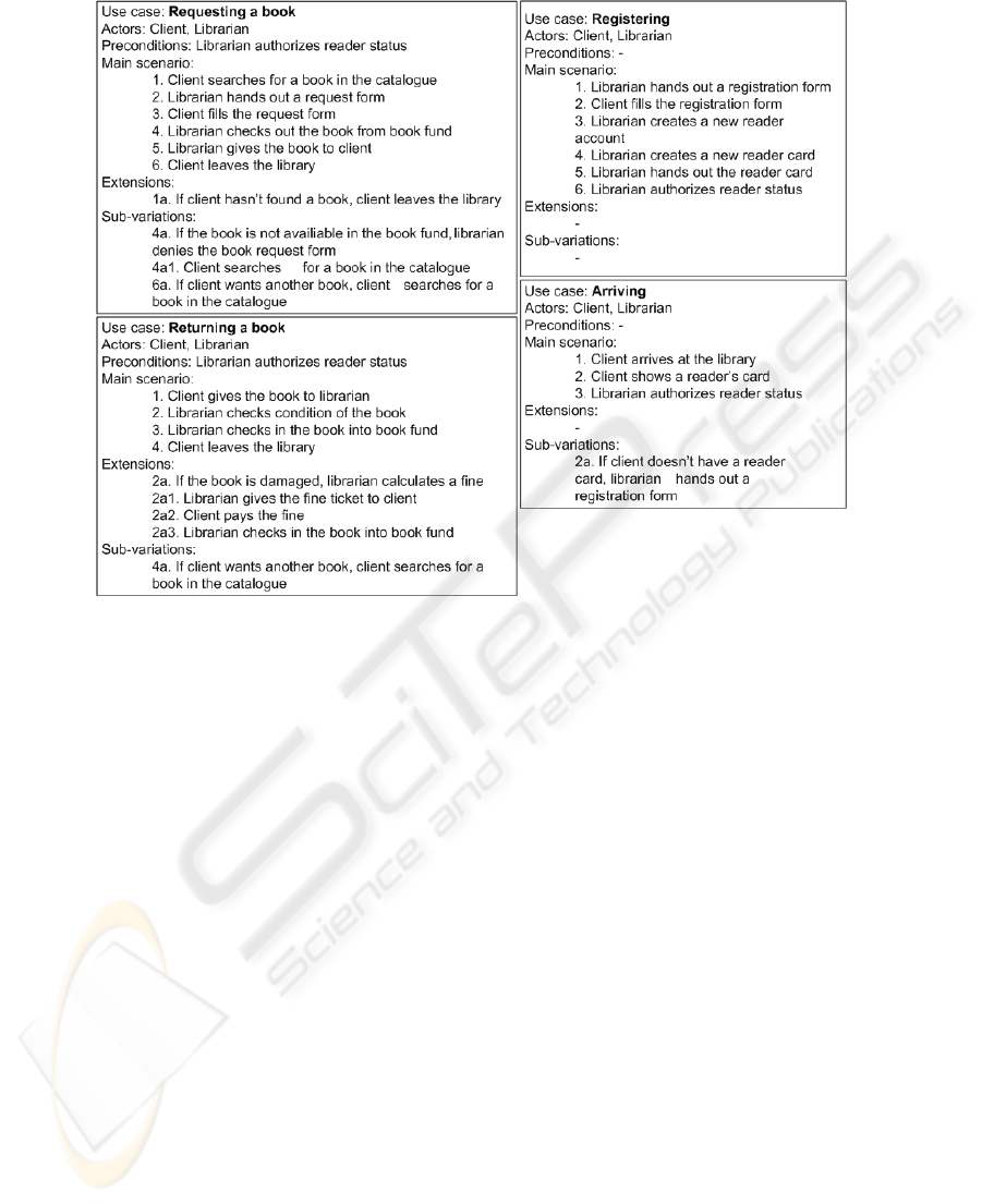
Fig. 1. Use cases for a library. This shows an example of business use cases for a library:
arriving, registering, requesting a book and returning a book.
5 Retrieving Functional Features
Functional features are represented by a tuple consisting of action, a set of
preconditions of this action, an entity responsible for this action, and subordination
[5]. As mentioned earlier an object action, a result of this action and an object
involved in this action are merged into action because of the complexity of text
analysis. One of the tasks of the TFM Fetcher component is to retrieve these
functional features from use cases.
Use cases are formed by sentences written in natural language. Every sentence,
except title and actors, in a use case can be considered as a representation of a
functional feature. Use case sentence can sometimes represent more than one
functional feature. This can happen when sentence consists of more than one result of
the action or objects involved in the action. Such an issue can be dealt with by
analyzing sentence’s coordinating conjunctions. For example in Fig. 1, if 2nd and 3rd
steps of use case “Requesting a book” are combined in one sentence “Librarian hands
out a request form and client fills the request form”. In this sentence the second
reference to a request form could be replaced by a pronoun “it”. This should be taken
into account. Moreover, the sentences of a use case should be written as simple and
unambiguous as possible, but in realistic case this is not always possible. In the
37

examples used in this paper use case step sentences are constructed to answer this
question – who does what? For example, “Librarian checks out the book from book
fund”. The verb phrase of the use case step’s sentence is considered the action.
Moreover, use case’s actors will be considered as objects involved in the action and
entities responsible for the action. The title can partly be considered as a functional
requirement.
TFM Fetcher component has to be able to form the corresponding functional
features by analyzing the use case sentences. For this purpose natural language
processing methods have to be applied.
Concrete syntax tree, or parse tree for short, will be used for the analysis of use
case sentences. Parse tree is a tree that represents the syntactic structure of a sentence
according to some formal grammar [15]. Parse trees are usually output of parsers,
which can use different methods for finding the right parse tree for the specific
sentence. The most efficient parsers are statistical parsers which associate grammar
rules with probability. For example, use case sentences “Librarian checks out the
book from book fund” will be parsed using The Stanford Parser [16]. By exploiting
statistical parser it is possible to acquire the structure of the sentence, and thus analyze
it. Stanford Parser creates a hierarchical structure of the sentence and ads the
corresponding Part-Of-Speech tags according to [17].
First an action of the corresponding functional feature has to be identified. In this
case it is the verb phrase (VP tag) of the sentence – “checks out the book from book
fund”. It consists of the object action (checks), the result of the action (book) and
object involved in the action (book fund). The responsible entity for the action can be
determined by comparing the actors list of the use case and the noun phrase (NP tag).
In this case the noun phrase is “Librarian” and there is “Librarian” in the actors list as
well, so the entity responsible for the action probably is “Librarian”. Preconditions
can be determined by analyzing the first steps of use case’s sub-variations and
extensions. If the current functional feature is represented as the first step of use case
main scenario, then one additional precondition will match the precondition of the use
case itself. If current step has a sub-variation, then the functional feature represented
by the next step will have a precondition that is the opposite of the sub-variation
condition. For example, sub-variation “If book is not available in the book fund,
librarian denies the book request form” will result in a precondition “Book is not
available in the book fund” for functional feature “denies the book request form”, but
an opposite precondition for functional feature “checks out the book from book fund”.
Use case extensions define their own precondition; obviously the condition in the
extension’s sentence is the precondition of the functional feature represented, but the
opposite precondition for the next step. Functional feature’s subordination can be
determined only by the user of the TFM Tool.
The identified functional features are represented as <number: action,
preconditions, responsible entity>. As mentioned earlier subordination can only be set
by the system analyst. By analyzing use case sentences the following functional
features can be derived: 1: Arrives at the library, {}, Client; 2: Shows a reader’s card,
{}, Client; 3: Authorizes reader status, {}, Librarian; 4: Hands out a registration form,
{Client doesn’t have a reader card}, Librarian; 5: Fills the registration form, {},
Client; 6: Creates a new reader account, {}, Librarian; 7: Creates a new reader card,
{}, Librarian; 8: Hands out reader card, {}, Librarian; 9: Searches for a book in the
catalogue, {}, Client; 10: Hands out a request form, {}, Librarian; 11: Fills the request
38

form, {}, Client; 12: Checks out the book from book fund, {}, Librarian; 13: Gives
the book to client, {}, Librarian; 14: Leaves the library, {}, Client; 15: Denies the
book request form, {The book is not available in the book fund}, Librarian; 16: Gives
book to librarian, {}, Client; 17: Checks condition of the book, {}, Librarian; 18:
Checks in the book into book fund, {}, Librarian; 19: Calculates a fine, {The book is
damaged}, Librarian; 20: Gives fine ticket to client, {}, Librarian; 21: Pays the fine,
{}, Client. It is important that TFM Fetcher considers functional features the same if
they are represented by the same tuple. This means that no duplicate functional
features are created and two or more use cases can include the representation of the
same functional features.
6 Retrieving Topology
Once there is a set of functional features it is necessary for TFM Fetcher to retrieve
the topology of TFM or cause-effect relations between functional features. The
structure of use cases will help with this task.
First of all, every use case’s main scenario is an ordered sequence of functional
features. Additionally, by analyzing the extensions and sub-variations it is possible to
detect branching in a TFM. Extension adds an effect to the functional feature
represented by the step referenced by the extension. On the other hand, sub-variation
adds an effect to the functional feature represented by the previous step referenced by
the sub-variation. Therefore, the setting of cause-effect relations between functional
features represented within the same use case is very straightforward. As you can see
in Fig. 2 the 4 main sequences of functional features come from main scenarios of use
cases. As a demonstration of use case extension and sub-variation analysis consider
functional features number 1 and 11. Functional feature number 1 has an additional
effect because of the sub-variation 2a from use case “Arriving”, but functional feature
11 has an additional effect because of the extension 4a from use case “Requesting a
book”.
A different task is setting the cause-effect relations between functional features
fetched from different use cases. Precondition section of use cases are used to define
this relation, because it contains the use case step which is the cause of the particular
functional feature. For example, use case’s “Requesting a book” precondition is
“Librarian authorizes reader status”, which is the 3rd step of use case’s “Arriving”
main scenario. Moreover, as different use case sentences represent the same
functional feature if their tuples conform, relation between different use cases can be
fetched from extensions and sub-variations, too.
Fig. 2 shows the compliance between the steps of use cases and the fetched TFM.
By analyzing the use cases it is possible to derive a TFM. TFM Tool will support
several iterations back and forth between description and TFM Fetcher until the
system analyst can verify every functional requirement. The mapping between use
case sentences, functional features and TFM should be intuitively illustrated and
easily editable, so that any incompleteness, redundancy or inconsistency could be
corrected. The main functioning cycle must be defined and set by the analyst. Cause-
effect relation between functional features 13 and 2 in Fig. 2 is set by the system
39
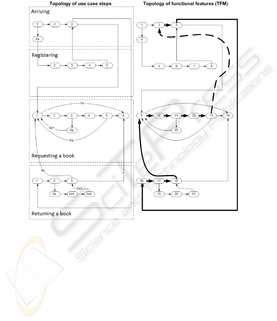
analyst for the completeness of main functioning cycle. It cannot be determined
automatically.
Fig. 2. This shows the topology use case steps in compliance with cause-effect relations
between functional features. The bold arrows represent the main functioning cycle of TFM.
7 Further Research
Further research is related to the evolution of the TFM Tool bringing its functionality
closer to TFM4MDA. First thing in queue is implementing the TFM Fetcher. It has to
be able to automatically retrieve functional features from its use cases by using a
statistical parser and then by the use of model transformation transform use cases to a
TFM. A metamodel for TFM is already defined in [9]. To solve the transformation
task a MOF compatible metamodel for a set of these use cases and a model
transformation conformable to QVT have to be developed.
40

Next task is to develop a TFM Transformer component which would transform
TFM to UML conforming to TFM4MDA. As mentioned before it will probably be a
special UML profile to keep all the valuable information of the TFM. So first there is
a need for a specific TFM UML profile. Then a TFM to UML profile transformation
has to be implemented with compliance to MDA standards. From this point it should
be possible to generate some part of the system’s code.
8 Conclusions
This paper discusses the specific text analysis tasks at the beginning of MDA life
cycle in context of TFM4MDA method like defining the knowledge about a system in
a formal data structure, challenges of retrieving a formal model from this knowledge
represented by use cases, implementing a workable transformation between a set of
system’s use cases and its TFM.
MDA proposes to abstract from application source code to the model of the
application as the main artifact in software development. Until now in MDA context
everyone has his own opinion about what is a CIM. This paper suggests that TFM
should be considered as the CIM of a system and proposes data structures and
methods for fetching a TFM from system’s use cases.
Business use cases with a specific template are used to define the knowledge about
the system. This is a promising solution because use case driven development is
widespread approach in software development. A statistical parser is used to analyze
the sentences of use cases, and thus retrieve functional features for a TFM of the
system. For retrieving the cause-effect relations between these functional features the
structure of the use cases is exploited.
With advancements of this research the completeness of MDA will improve.
TFM4MDA provides a formal CIM and new horizons by partially automating and
improving system analysis.
References
1. Frankel, D.S.: Model Driven Architecture: Applying MDA to Enterprise Computing.
Wiley, Indianapolis (2003)
2. Gasevic, D., Djuric, D., Devedzic V.: Model Driven Architecture and Ontology
Development. Springer, Heidelberg (2006)
3. Meta Object Facility (MOF) 2.0 Query/View/Transformation Specification,
http://www.omg.org/cgi-bin/doc?ptc/07-07-07.pdf
4. Osis, J.: Topological Model Of System Functioning (in Russian). In: Automatics and
Computer Science, J. of Acad. of Sc., pp. 44--50, Zinatne, Riga (1969)
5. Osis, J., Asnina, E., Grave A.: Computation Independent Representation of the Problem
Domain in MDA. J. Software Eng. vol. 2, iss. 1, 19--46, http://www.e-informatyka.pl/e-
Informatica/Wiki.jsp?page=Volume2Issue1 (2008)
6. Kontio, M.: Architectural manifesto: Choosing MDA tools,
http://www.ibm.com/developerworks/library/wi-arch18.html (2005)
7. Asnina, E.: T he Formal Approach to Problem Domain Modeling within Model Driven
41

Architecture. In: 9th International Conference on Information Systems Implementation and
Modelling, pp. 97 – 104. Prerov, Czech Republic, Ostrava (2006)
8. Osis, J., Asnina, E.: Enterprise Modeling for Information System Development within
MDA. In: 41th Annual Hawaii International Conference on System Sciences, pp. 490.
HICSS, USA (2008)
9. Šlihte, A.: The Concept of a Topological Functioning Model Construction Tool. In: 13th
East-European Conference, ADBIS 2009, Associated Workshops and Doctoral Consortium,
Local Proceedings, pp. 476--484. JUMI, Riga, Latvia (2009)
10. Francu, J., Hnetynka, P.: Automated Generation of Implementation from Textual System
Requirements. In: Proceedings of the 3rd IFIP TC 2 CEE-SET, pp. 15--28. Brno, Czech
Republic, Wroclawskiej (2008)
11. Structural Requirements Language Definition, Defining the ReDSeeDS Languages,
http://publik.tuwien.ac.at/files/pub-et_13406.pdf
12. Subramaniam, K., Liu, D., Far, B., Eberlein, A.: UCDA: Use Case Driven Development
Assistant Tool for Class Model Generation. In: Proceedin of the 16th SEKE. Banff,
Canada, http://enel.ucalgary.ca/People/eberlein/publications/SEKE-Kalaivani.pdf (2004)
13. Overmyer, S., Lavoie, B., Rambow, O.: Conceptual Modeling through Linguistic Analysis
Using LIDA, In: Proceedings of the 23rd International Conference on Software
Engineering, pp. 401--410. Toronto, Ontario, Canada (2001)
14. Malan, R., Bredemeyer, D.: Functional Requirements and Use Cases,
http://www.bredemeyer.com/pdf_files/functreq.pdf
15. Jurafsky, D., Martin, J.H.: Speech and Language Processing: An Introduction to Natural
Language Processing, Computational Linguistics, and Speech Recognition. Pearson
Education (2000)
16. The Stanford Parser: A statistical parser. The Stanford Natural Language Processing Group,
http://nlp.stanford.edu/software/lex-parser.shtml
17. Part-Of-Speech Tagging Guidelines for the Penn Treebank Project (3rd revision, 2nd
printing), http://www.ldc.upenn.edu/Catalog/desc/addenda/LDC1999T42/TAGGUID1.PDF
42
