
Transformations of Software Process Models to Adopt
Model-Driven Architecture
Vladimirs Nikulsins
Riga Technical University, Meza 1/3, LV-1048 Riga, Latvia
Abstract. This paper proposes a solution on how to adopt software develop-
ment process and make it compliant with the Model Driven Architecture by
OMG. Process modeling languages helps to formalize the knowledge about the
software development life cycle expressed in tasks, activities, phases,
workflows and roles. SPEM (Software Process Engineering Meta-Model) is
OMG standard used to describe a software development process within an or-
ganization. The proposed solution is to transform any so called “traditional”
software development life cycle model into the model-driven with the help of
model transformations written in Query/View/Transformation (QVT) language.
This approach has been partially approbated in one of the Latvian IT compa-
nies.
1 Introduction
MDA (Model Driven Architecture) is OMG (Object Management Group) paradigm
that focuses on the software development process using modeling and model trans-
formations. Within MDA the software development process is driven by modeling the
software system rather than producing the code: models are transformed into the
working code through the various automated and semi-automated transformations.
No specific software development methodology is proposed by OMG and so MDA
can fit into any software development process. This allows a certain flexibility, and at
the same time, a lack of formalized knowledge on adapting the model-driven devel-
opment to the software development methodologies used in practice. Process model-
ing activity helps to describe the appropriate software development activities and
their relations in the software development life cycle (SDLC).
SPEM (Software Process Engineering Meta-Model) [1] is OMG standard for
process modeling; it is a standard object-oriented meta-model defined as an UML
profile. SPEM can be examined in relation to the definition areas of project manage-
ment and software life cycle processes.
The author of this paper has started his research on the methodology of the inte-
gration of MDA into the traditional software development lifecycle earlier [2], [3],
[4], [5], [6]. Software development activities, workflows and software development
team organization were also analyzed in previous researches [7], [8]. The author was
also involved in the projects where a technical solution to support software develop-
ment process transition from “traditional” software development process to the MDA
compliant process using process models and model-driven transformation approach
Nikulsins V. (2010).
Transformations of Software Process Models to Adopt Model-Driven Architecture.
In Proceedings of the 2nd International Workshop on Model-Driven Architecture and Modeling Theory-Driven Development, pages 70-79
DOI: 10.5220/0003044500700079
Copyright
c
SciTePress

was provided: the source model presenting “traditional” software development
process is transformed to the target model, which presents the MDA-based software
development process using QVT transformations [2], [6]. This approach was recently
approbated within one of Latvian IT development companies that develops applica-
tions for tourism agencies.
The objective of this paper is to propose a solution on how to transform software
process models to adopt Model-Driven Architecture. It briefly describes the steps
which should be completed to implement this approach in practice, and provides
comments on approbation analysis of the solution proposed. This paper also unifies
previous author researches.
In practice, model development process for the “traditional” software development
life cycle and its subsequent transformation into the corresponding model-driven
model using SPEM notation allow to achieve formalization of process architect’s
knowledge.
The structure of this paper is organized as follows. Current section provides gener-
al introduction to the problem area. Next sub-section outlines overview of related
works. Section 2 provides solution framework. It is then followed by two sub-
sections: “Technical Design for Transforming SPEM Models”, which describes this
solution for Eclipse platform, and “Tools for Process Modeling”. Next section de-
scribes limitations and outlines the key points when approbating this solution in prac-
tice. Final section contains the conclusions.
1.1 Related Work
In addition to the work mentioned in introduction, the following papers described
below are a subject of interest for software development process engineers working
with MDA.
General Standard Software Process is applied to MDA in SPEM within MASTER
project [9]. It provides standard workflows and activity model using SPEM 1.0.
The authors of [10] enhance SPEM with the Object Constraint Language (OCL)
[11], because it lacks a formal description of its semantics. SPEM is rather general
and OMG provides no directives on how to use it.
It is possible to transform SPEM models to other software processes notations.
[12] proposes its own solution on how to map the SPEM and XPDL, naming the
approach SPEM2XPDL. The mapping is done using major entity-mapping table.
During transformation such entities are given with default values. The transformation
algorithm is provided, and is also implemented using SoftPM software. The process
meta-models integration and unification problem is reviewed in [13]. This paper
named “Process-Centered Model Engineering” was written almost 10 years ago;
however, currently the problem became even more serious because of the amount of
different MOF implementations. [14] investigates different approaches to model
transformations. Particularly, attention is paid to OMG’s Que-
ries/Views/Transformations (QVT) [15]. Authors also review problems of tracing
activities and model conformance, when changes are done on both the source and the
target models. Unification of declarative and imperative issues on model transforma-
tions is proposed by adopting a new ap-
71

proach to model transformations.
2 Solution Framework
When planning the transition from the “traditional” software development process to
the model-driven development, the first thing to start with is the analysis of the cur-
rent software development process. Here, help from experienced MDA process archi-
tect consultants might be required. One of the OMG initiatives for smooth transition
to MDA is a special program “MDA FastStart”. It is divided into three main phases –
an assessment, an overview and a transition [16].
However, these actions are mainly based on the expertise of consultants, and are
not formalized into some specific framework or methodology. Using the approach
described in this paper, it is possible to formalize some part of the transition process,
which covers the software development description and the transition to MDA
process through the process model.
In the previous works of the author, software development process (SWEBOK),
standards (ISO, CMMI) and methodologies (RUP, MSF, XP) were investigated.
Model-Driven Development was also analyzed and decomposed into static and dy-
namical representation, as well as linked from methodological point of view to RUP,
MSF and general guidelines for any software development process [3], [4]. The
process static and dynamical representation consists of two objects. The same repre-
sentation is used in RUP [17].
• The first one represents static aspects of a process. They are expressed in terms
of process components, activities, workflows, artifacts and roles
• The second one represents dynamical aspects of a process. They are expressed
in terms of cycles, phases, iterations and milestones
Additional sources of information were investigated from various researches and case
studies on model-driven development and its specific aspects utilization. As a result,
it has lead to the gathering of information for both “traditional” software development
and model-driven.
Such decomposition of the process model elements allows linking the activities
from “traditional” processes to model-driven (for example, PIM modeling activity
instead of coding). All elements of the process model can be formalized into chosen
process model notation, and decomposed with the help of base building blocks (enti-
ties, which exist in every software development process). The usage of base building
blocks in the process modeling allows to avoid problems of unified terminology,
since the same activities may be named differently, and also different process archi-
tects can produce different models. A similar approach is implemented in the process
modeling tools like Eclipse EPF [18].
OMG standard for the modeling software life cycle processes is SPEM. The proc-
ess models should be expressed using SPEM base building blocks. In order to link
them, the usage of the special language is required. Linking base building blocks
means that it is possible to transform one model into another: from “traditional” soft-
ware development process model into MDA. The language used for linking is another
of OMG proposals – QVT Relations.
72
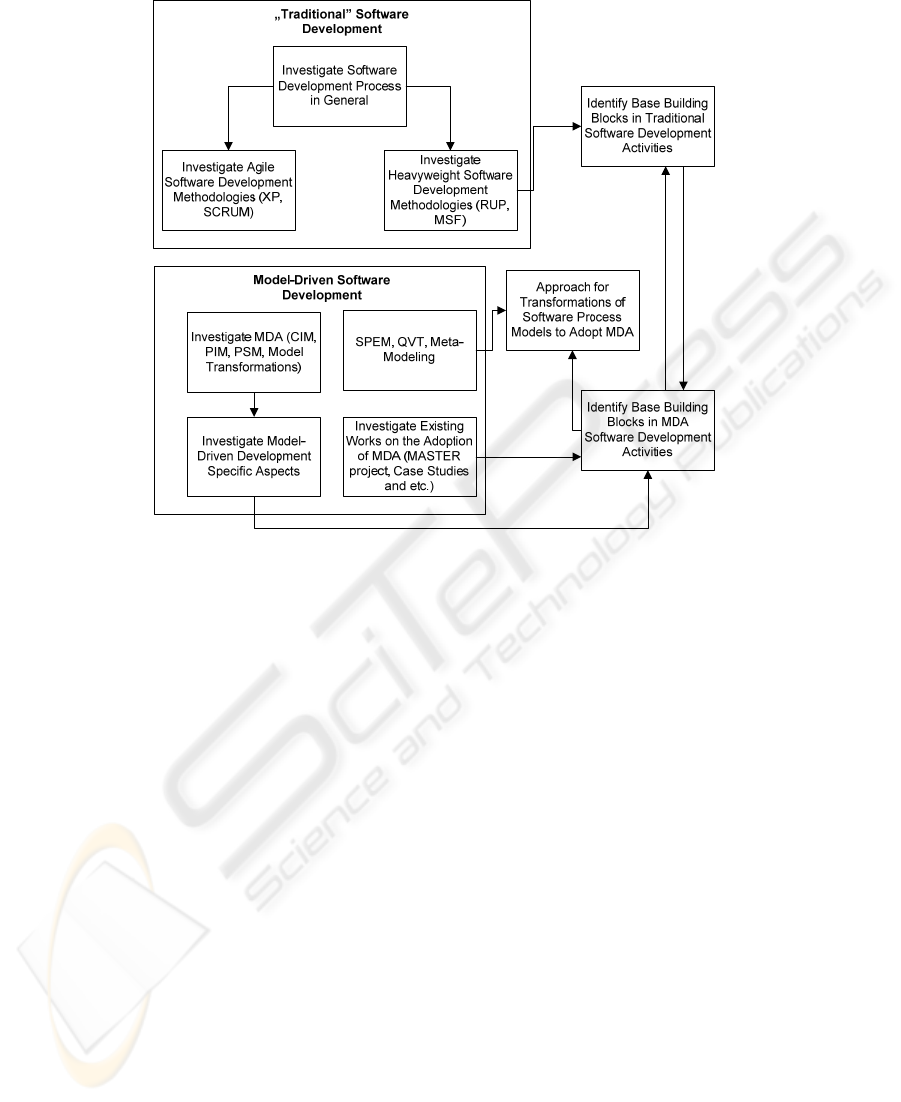
Fig. 1. Knowledge flow to develop an approach for process model transformation.
As a result, it is possible to create a process model of “traditional” software devel-
opment process in SPEM, execute QVT transformation and get an MDA based soft-
ware development process model.
The information flow and graphical representation of the approach presented is
depicted on Fig. 1.
There are also additional conditions which should be taken into account. E.g., the
correct sequence of SPEM elements, and also the check for the model validity (OCL
can constrain this to some point). More detailed information on reasoning and the
approach proposed can be found from [2], [6].
2.1 Technical Design for Transforming SPEM Models
This section describes technical design for the solution described in the previous
section. Eclipse is chosen as a general integration platform. An additional deliverable
is partially implemented QVT rules (not described in this paper).
High-level approach consists from the following steps:
1. Choose the process modeling notation
2. Create process model using the chosen notation (process currently used in
the Company)
3. Create the process model using SPEM v2.0 (as input use the model created
in the previous step)
73
4. Define the transformation rules and algorithms for transforming SPEM mod-
el representing the Company’s process model to the SPEM model
representing model-driven development
5. Execute the transformation
In order to handle and constrain the whole SPEM process modeling for the organiza-
tion and SPEM transformation processes, several requirements are defined under the
solution offered in this paper:
1. The process architect represents the current software development process
using the base building blocks (Open UP based process used as a source)
2. The elements, that cannot be represented using the base building blocks
should be placed into the model, and linked with existing building blocks. It
means that all the process building blocks should be linked together – at
least one link for the element must exist
3. To avoid incorrect interpretation of the elements and ease the understanding
of concepts – both the base building block names and the software develop-
ment organization’s identified element names should be used. This allows
unifying terminology and different naming descriptions for the same ele-
ments.
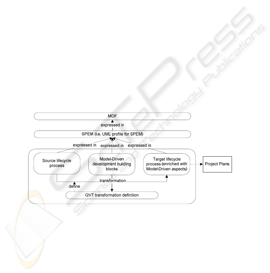
The transformation rules should be defined with the help of QVT (Query/
View/Transformation) standard. The architecture of this solution is depicted on Fig.2.
In this approach QVT Relations is used. The base building blocks are based on Open
UP, which allows to unambiguously link them with the corresponding model-driven
activities.
Fig. 2. SPEM model-to-model transformation architecture.
The method of applying SPEM transformations based on the pre-defined QVT
rules allows to partially automate the work of the process engineer and support them
(with the model-driven development lifecycle utilization. The architecture and actions
needed for the implementation of the transformation are described in detail in [6].
The architecture on the Eclipse platform is depicted by Fig. 3. Firstly, building of
SPEM model which represents the “traditional” software development is required. It
might be composed from both Open UP base building blocks (such building blocks
74
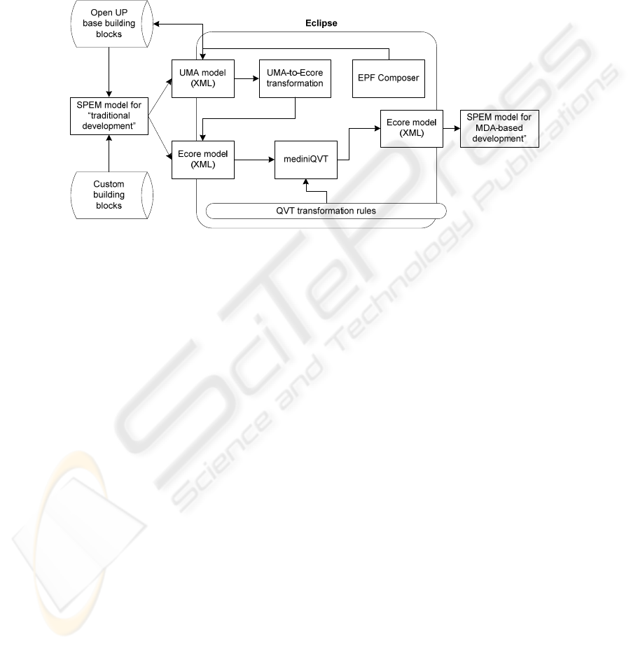
can include activities, their relations, processes, milestones, roles and etc.), and cus-
tom building blocks (e.g., some organization-specific activities). All of them should
be linked together in one model. SPEM model should be exported to the Ecore
model. The QVT plug-in mediniQVT works with Ecore models, so this is a manda-
tory requirement. Once the source model is loaded into mediniQVT, a transformation
should be initialized. A result of the transformation is SPEM model in Ecore, which
represents the model-driven software development life cycle for the organization.
Fig. 3. SPEM model integration schema in Eclipse.
The process definition is as follows:
The steps below represent the process dynamical flow. Number labels represent
the goals (what happened when the goal has been achieved), and the letter labels
represent the actions/tasks (actions which need to be performed):
1. Define and validate SPEM v2.0 Ecore metamodel
a) Create the metamodel using Sample Ecore Editor or
b) Create the metamodel using Graphical editor Ecore Tools
2. Define QVT relations transformations
a) Copy all SPEM elements from the source model to the target model
(phases, activities, tasks and their relationships)
b) Define QVT Relations transformations for SPEM elements converted in
a model-driven context. This will allow modifying the current model
without changing non-standard elements
c) Define the output model, which helps to avoid transformation within the
same model
d) Define the direction of the transformation (from the source model repre-
senting the traditional software development, to the output, representing
the model-driven software development)
3. Execute QVT relation transformation, and generate the output model.
75

2.2 Tools for Process Modeling
There are various tools that support SPEM notation in the software development life
cycle modeling. One of most widely known is IBM Rational Architect, where SPEM
is used as a core notation for representing the process workflow. It is possible to
transform SPEM model into the different information sources. E.g., align tasks from
SPEM in Microsoft Project, or save its structure in XML [1]. SPEM notation is used
as a main notation for RUP activities and processes representation.
Objecteering SPEM Modeler is a BPMN graphical editor that supports complete
UML2 standard modeling and BPMN modeling for business processes integrated
with UML. It also provides various transformation possibilities [19].
MagicDraw UML 16.0 (with SPEM extension). This tool is fully UML 2.0 com-
pliant. The tool supports UML 2.0 standard, code engineering for multiple program-
ming languages (Java, C++, C# and others) as well as for data modeling. The tool has
teamwork facilities and supports integration with the various IDEs. MagicDraw has
integration with various MDA tools: Compuware OptimalJ, AndroMDA, Interactive
Objects' ArcStyler and etc [20]. There are two add-ons available, which are the most
important in relation to this research. These are methodology wizard and SPEM plug-in.
The main process modeling tool in Eclipse, which is used as a platform for the
proposed solution, is called EPF Composer. It is a tool aimed to produce a customiza-
ble software process engineering framework. Once the model is defined in the EPF, it
can be exported to the external file in XML format. The Eclipse package in which
EPF Composer models are stored is called UMA.
Model transformations are performed using mediniQVT tool that can operate with
the models expressed as Ecore metamodels and provides debugging features and
transformation rules tracing. The QVT Relations transformations are applied to the
source model that corresponds to the “traditional” software development lifecycle.
mediniQVT uses Eclipse platform as well.
2.3 An Example of QVT Relations Transformation
The following subsection illustrates a trivial example of QVT Relations language,
which in this paper is suggested for transforming SPEM models. The top relation is
called “DrawBP2CreateBPmodel”. It changes the name attribute for the activity
“Draw business process diagram”. Both the source model openup and the target mod-
el mdd belong to the same metamodel SPEM, which is expressed in Ecore format.
transformation SPEMtoSPEM(openup:SPEM, mdd:SPEM)
{
-- Copy source activity to target, changing the activity name,
-- occurs only for Initial phase
top relation DrawBP2CreateBPmodel
{
checkonly domain openup p:Activity{
name = “
Draw business process diagram”;
owningPhase = "Initial";
};
enforce domain mdd s: Activity {
name = “Create business process model”
};
}
76

3 Limitations and Approbation Analysis
The ongoing discussion regarding the usage of the software development process life
cycle notation is mainly concerned with choosing the right balance between the stan-
dards accepted in the industry, the requirements of the clients and overall simplicity
of usage. The initial modeling idea is that the graphical representation and drawing
diagrams are a step towards simplifying the development process and enhancing the
abstraction level. Diagrams are meant to be more understandable for both business
stakeholders and programmers. However, in practice various developers and process
architects are facing the problem of the inappropriate diagram expressivity. To solve
this issue, the notations are being enriched and logical components are being added
(e.g., introducing new elements are introduced, OCL or linking to other notation are
added) [21].
The development of the various kinds of extensions can be helpful for a particular
project, however looking from the wider perspective it would limit the possibilities
of re-using the solution for different kinds of projects. Even when the desired solution
is implemented in development tools, this raises an interoperability issue – as various
formats are not supported, the need to convert formats arises.
The solution proposed by the author in this paper is limited to the integration with-
in the Eclipse platform only; it fails to solve one of the biggest problems – finding the
way to integrate the SPEM model into any tool and from any other tool. In order to
integrate every modeling tool that is using SPEM as a metamodel, it is necessary to
define the transformation chain for every unique format used by the modeling tools.
However, with some rework, the concepts presented in this paper can be applied to
any software development process modeling tool.
When the author of this paper was working on developing the model of existing
“traditional” software development life cycle for one of Latvian IT companies, the
biggest problem he came across was the difference in detail levels. In practice it
provides the general understanding of the software development process, but at the
same time it might appear not to be detailed enough to link the SPEM model with the
corresponding base building blocks.
In addition, the following restrictions have been identified: the model-driven
process model obtained from the initial model cannot replace the “action plan” for the
manager. It also provides no insight into specific MDA transformation tools and
chains, since a different reasoning on the process of MDA toolset selection would be
necessary, for example [22].
The usage of MDA process is believed to be reasonable only in the long-term,
since if the organization tries to change their current process immediately, it will have
to face extra costs associated with training, re-building of their existing assets, buying
new licenses for tools, changing the way they support their clients (as the organiza-
tion switches to a different development paradigm), and etc.
The company analyzed by the author is dependent on IBM Lotus client-server plat-
form. If the is a need to move to a newer platform or provide different kinds of ser-
vice arises for them, MDA implementation might be an option.
Another important aspect identified during the approbation is the difference in
stakeholders’ expectations. The management of the company wanted to get a ready-
77

to-use solution with all the tools and transformation chains defined in place. Howev-
er, this research is limited to the definition of the process model and executing trans-
formations only, thus it formalizes only a part of process architect knowledge. It can-
not fully replace human expertise.
4 Conclusions
It is suggested that it is possible to represent any software development life cycle
using SPEM and appropriate base building blocks. To perform that, no knowledge
about MDA is needed. SPEM is OMG standardized notation and is successfully used
for different types of life cycles. Using the process model developed when imple-
menting SPEM and the appropriate base building blocks it is possible to get the MDA
compliant model by transforming source SPEM model with QVT.
This paper provides a framework for implementing the above mentioned approach
of transforming source SPEM model with QVT to get the MDA compliant model.
When used in practice, this approach has several limitations that were identified when
approbating the solution in practice for one of Latvian IT companies. However, it is
important to mention, that this approach allows to link any “traditional” software
development process with the model-driven development process, and also formalize
some MDA expertise by using MDA
In future author of this paper is planning to take more detailed investigation on this
problem area, and present complete methodology together with a full set of base
building blocks to achieve higher levels of usability.
References
1. Software Engineering Institute. Capability Maturity Model Integration (CMMI),
http://www.sei.cmu.edu/cmmi/
2. Nikulsins, V., Nikiforova, O.: Tool Integration to Support SPEM Model Transformations in
Eclipse. The 50th International Scientific Conference of Riga Technical University. RTU.
(2009)
3. Nikiforova O., Nikulsins V., Sukovskis U.: Integration of MDA Framework into the Model
of Traditional Software Development, In the series “Frontiers in Artificial Intelligence and
Applications", Databases and Information Systems V, Selected Papers from the Eighth In-
ternational Baltic Conference Baltic DB&IS 2008, Haav H.-M., Kalja A. (Eds.), IOS Press
(2009) 229-242
4. Nikulsins, V., Nikiforova, O., Sukovskis, U.: Mapping of MDA Models into the Software
Development Process, Databases and Information Systems, Proceedings of the Eighth In-
ternational Baltic Conference Baltic DB&IS 2008, H.-M. Haav and A. Kalja (Eds.), Tallinn
University of Technology Press, Tallinn, Estonia, June 2-5 (2008), 217-226.
5. Nikulsins V., Nikiforova O.: Adapting Software Development Process towards the Model
Driven Architecture, Proceedings of The Third International Conference on Software Engi-
neering Advances (ICSEA), International Workshop on Enterprise Information Systems
(ENTISY), 2008, Mannaert H., Dini C., Ohta T., Pellerin R. (Eds.), Sliema, Malta, Octo-
ber 26-31, 2008., Published by IEEE Computer Society, Conference Proceedings Services
(CPS), 394-399.
78

6. Nikulsins V., Nikiforova O.: Transformations of SPEM Models Using
Query/View/Transformation Language to Support Adoption of Model-driven Software De-
velopment Lifecycle. The 13th East-European Conference on Advances in Databases and
Information Systems (ADBIS), September 2009. Riga, Latvia, JUMI Publishing House
Ltd. (2009).
7. Nikulsins, V., Nikiforova O., Sukovskis U.: „Analysis of Activities Covered by Software
Engineering Discipline”, Databases and Information Systems, Seventh International Baltic
Conference on Databases and Information Systems, Communications, Materials of Doctor-
al Consortium, O. Vasilecas, J. Eder, A. Caplinskas (Eds.), pp. 130-138, VGTU Press
„Technika” scientific book No 1290, Vilnius, Lithuania (2006)
8. Nikulsins, V., Nikiforova, O.: “Software Development Teams Organization”, The 46th
Scientific Conference of Riga Technical University, Computer Science, Applied Computer
Systems, October 13-14, Riga, Latvia, 2005, published in the 5th Series “Computer
Science. Applied Computer Systems, Vol. 26 (2006), 54-65
9. Model-driven Architecture inSTrumentation, Enhancement and Refinement. Process Model
to Engineer and Manage the MDA Approach, 2003. – Spain: European Software Institute –
http://modeldrivenarchitecture.esi.es/pdf/Deliverable-D32.zip (2003)
10. Combemale, B., Cregut, X. Towards a Rigorous Process Modeling With SPEM. – France:
Rennes University – http://www.combemale.net/research/phd/2006/iceis250406-CCCC-
poster401.pdf (2006)
11. Object Constraint Language Specification, version 2.0. Prepared by OMG: OMG –
http://www.omg.org/cgi-bin/apps/doc?formal/06-05-01.pdf (2006)
12. Feng, Y., Mingshu L., Zhigang, W. SPEM2XPDL: Towards SPEM Model Enactment.
SER5202.pdf. – Bejing, China: The Chinese Academy of Sciences (2006)
13. Breton, E., Bezivin, J. Process-Centered Model Engineering. Proceedings of the 5th IEEE
International Conference on Enterprise Distributed Object Computing, p.179 (2001)
14. Tratt, L. Model transformations and tool integration. – London, UK: Department of Com-
puter Science, King’s College London, Springer-Verlag (2004)
15. Meta Object Facility (MOF) 2.0 Query/View/Transformation, v1.0. Prepared by OMG:
OMG – http://www.omg.org/docs/formal/08-04-03.pdf (2008).
16. OMG. Model Driven Architecture. Prepared by OMG: OMG – http://www.omg.org/mda.
17. Kruchten, P.: The Rational Unified Process An Introduction, Second Edition, Addison
Wesley (2000)
18. Eclipse Process Framework (EPF). Prepared by Eclipse Foundation: Eclipse –
http://www.eclipse.org/epf. (2009)
19. Objecteering, http://www.objecteering.com/products_uml_modeler.php
20. MagicDraw UML, http://www.magicdraw.com
21. Bendraou, R., Combemale, B., Cregut, X., Gervais, M.-P. Definition of an eXecutable
SPEM 2.0. Asia-Pacific Software Engineering Conference (APSEC), Nagoya: Japan (2007)
22. Nikiforova O., Cernickins A., Pavlova N.: On the Tool Chain for Model Driven Architec-
ture and Model Driven Development: Drawing a Distinction. The 13th East-European Con-
ference on Advances in Databases and Information Systems (ADBIS), September 2009. –
Riga, Latvia: JUMI Publishing House Ltd., pp. 408-415 (2009)
79
