
Realizing Use Cases for Full Code Generation in the
Context of fUML
Ioan Lazar, Simona Motogna, Bazil Pˆarv and Codrut-Lucian Lazar
Department of Computer Science, Babes¸-Bolyai University
Cluj-Napoca 40084, Romania
Abstract. We describe a pragmatic method for developing use case realizations
as Foundational UML (fUML) active objects. The method allows developers to
transform the textual representations of use cases into executable UML activities
which represent the classifier behaviours of the corresponding use case realiza-
tions. The generated graphical representations help developers to find require-
ments defects. Moreover, developers implement the required system behaviour
by adding code using again a concrete textual syntax for fUML. The result is
an executable fUML model which helps developers to simulate and validate the
implemented behaviour. Finally, completed code may be generated towards the
existing platform specific frameworks which use structured programming con-
structs.
1 Introduction
Use cases introduced by Jacobson around 1992 [1] represent a technique for capturing
the required behaviour of a software system. Accommodating the needs of different
roles of software development projects implies accommodating informality with neces-
sary precision in use case scenarios [2].
Analysts write use cases to communicate their understanding of the required system
behaviour,while stakeholders participate in formulating use cases to make sure their re-
quirements are communicated well. Both these roles require the use of simple sentences
written in natural language in one of many suggested template formats. The template
formats usually suggest that sentences should be ordered and numbered for easier ref-
erence. Starting from (informal) textual representations of use cases, developers build
models based on formal notations where scenarios are described as sequence of mes-
sages within interaction diagrams or as sequence of actions within activity diagrams.
Our investigations refer to the developer’s tasks, in the context of Model-Driven
Architecture [3] and the Foundational Subset for Executable UML (fUML) [4]. The
first question we address here is this: can we capture use case scenarios as fUML mod-
els such that a suite of closely related and transformable notations enables a pragmatic
translation from informal textual descriptions into executable models? For a given use
case, we want an approach that (a) allows developers to capture its scenarios using a
textual description which is automatically compiled as fUML models (using UML ac-
tivities). (b) An automatically generated activity diagram should allow developers to see
graphically all use case scenarios. This step could help developers to find requirements
Lazar I., Motogna S., Pârv B. and Lazar C. (2010).
Realizing Use Cases for Full Code Generation in the Context of fUML.
In Proceedings of the 2nd International Workshop on Model-Driven Architecture and Modeling Theory-Driven Development, pages 80-89
DOI: 10.5220/0003049700800089
Copyright
c
SciTePress

defects by analyzing the control flow of the generated scenarios. (c) Next, developers
implement the scenarios based on an established architecture. The method should allow
developers to implement scenarios separately although all scenarios are represented by
a UML activity. They define statements using a convenient concrete textual syntax for
each action generated at step (a). (d) Developers can run all scenarios even not all of
them are yet implemented. A step by step simulation performed on the activity diagram
could help developers to find design defects.
Representing the scenarios of a use case using a single UML activity enables the
capture of precise and analyzable use cases. For complex use cases this representation
may lead to arbitrary cycles (looping that is unstructured or not block structured). So,
the second question is: can we generate code towards the existing platforms which use
only block structured loops? The concrete textual syntax should be designed to enable
code generation towards today platform specific frameworks. Moreover, the generated
code is meant to be complete, with no code placeholders for the developer to fill.
In this article we analyze how the fUML constructs can be used for modelling use
case scenarios towards the above goals. The proposed pragmatic approach captures the
scenarios from a business perspective and then makes them executable. The visualiza-
tion of complex scenarios in a single diagram allows developers to intuitively analyze
the system behaviour. From a developer perspective, it is much more convenient to use
textual rather than graphical notations. Our approach follows this requirement.
The paper is organized as follows: Section 2 contains some brief preliminaries, Sec-
tion 3 presents the concrete textual syntax, and Section 4 discusses the scenario imple-
mentations using action languages for fUML. In section 5 we discuss related work,
while the last section contains conclusions and future works.
2 Preliminaries
In search for a concrete textual syntax for use case realizations we start with general
definitions of use case and scenario. A common template for writing use case actions
must be identified and the key elements for realizing use cases in the context of fUML
must be analyzed.
As an example, we consider a word guessing game in which a word is displayed
with its character order randomized. The user must enter the correct spelling to win
points and progress to the next word. Each word has an assigned point value. The ap-
plication should allow users to administer the words and their assigned points. The use
case model and user interface sketches are shown in Figure 1.
Use Cases and Scenarios. As in [2], for the purpose of this article we consider the
following definitions of Cockburn [5]: a use case is a collection of possible scenarios
between the system and external actors, and a scenario is a sequence of interactions
starting from an actor’s triggered action. These definitions do not enforce any particular
notation. We further need a general template for writing the scenarios of a use case. We
use the results of [6, 7] for specifying use case interactions.
Collected during the inception phase of a project (prior to architecture definition
and design), use cases captures what the system will do in terms of the domain ele-
ments using 4 basic actions and 4 flow of control actions. The basic actions refer to:
81
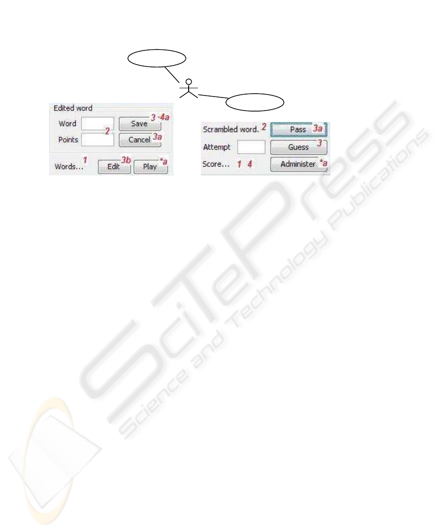
Basic flow
1 System sets score to zero
2 System sets scrambled word
3 User makes an attempt to guess
4 System checks the attempt and adjust the score
Steps 2-4 may repeat
Alternative flows
3a User passes the current word
*a User wants to administer
Basic flow
1 System displays the word list
2 System sets edited word to a new word
3 User saves the edited word
4 System persists the edited word
Steps 1-4 may repeat
Alternative flows
3a User cancels editing
3b User edits an existing word
4a User entered invalid data
*a User wants to play
Play
Administer
User
Fig.1. Scramble Use Case Model.
providing input to the use case, returning output to an actor, performing a computation
using provided input and domain information, and responding to an issue (exception
handling) with the input or state of the domain instances. The flow of control actions
are: selection - conditionally execute actions, iteration - repeatedely execute an action
sequence, inclusion - include the behaviour of another use case, and extension - define
the extension point for an extending use case.
Figure 1 shows two use cases and their textual descriptions according to the recom-
mendations given in [8]. The use cases are named with an active verb phrase that repre-
sents the goal of the actor. The success stories are written as simple scenarios without
any consideration for possible failures or alternatives. The alternatives that may occur
are placed below the success stories. All alternatives and failures are captured, but no
details are given due to space limitations (the next section presents detailed descrip-
tions). The steps show clearly which actor is performing the action, and what the actor
gets accomplished.
In terms of the action types presented above, only the basic flows contain basic
actions. The step 3 represents an input action in both descriptions. The first step of
Administer
is an output action, while the steps {2, 4} of
Administer
and {1, 2, 4}
of
Play
are computation actions. The steps 3a and 3b represent exception actions -
alternativeinput actions executed by the user instead of executing the input action 3. The
step 4a of
Administer
is also an exception - alternative to a system action, also known
as conditional insertion [6]. The steps marked by asterisks are also exceptions to input
actions that can be executedat any time. Related to the flow of control actions, iterations
are indicated in both basic flows. Figure 1 does not contain selection, inclusion, and
extension actions. Details about these action types will be given in the next section.
Realizing Use Cases in fUML. Executable UML [9] means an execution semantics for
a subset of actions sufficient for computational completeness. Today, the effort of defin-
ing a standard execution semantics enters the final state of adoption. Foundational UML
82
defines a “basic virtual machine for the UML, and the specific abstractions supported
thereon, enabling compliant models to be transformed into various executable forms”
[4]. fUML structural constructs do not include components, composite structures, and
collaborations, while the behavioural constructs do not include interactions and state
machines. In this context the system structure is defined using packages, classes, prop-
erties, associations, and operations, while the system behaviour is defined through ac-
tivities.
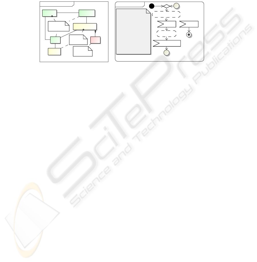
Logical architecture[ ]
WordRepository
AdministerScramble
Random
WordPlay
active classes
domain class
components
0..*
Scrambleactivity
1 Start administer
4 Administer
3 Start play
*a Exit2 Play
A
A
Basic
1 Start administer
2 Accept play
3 Start play
4 Accept administer
5 Rejoin at 1
Alternatives
*a Accept exit
*a.1 Finish
Fig.2. Logical Architecture and Use Case Integration.
Bounded by the current fUML specification, the input actions corresponding to the
actor’s triggered events must be mapped to fUML accept event actions. In consequence,
use case realizations in fUML must be active classes because the context of the contain-
ing activity of an accept event action must be an active class. An active class is a class
whose instances have independent threads of control. The behaviour of an active class
is defined by its classifier behaviour, so, the entire set of scenarios described for a use
case will be defined by an activity which is set as the classifier behaviour of an active
class. For example,
Administer
and
Play
in Figure 2 are active classes which represent
the realizations of use cases presented in Figure 1.
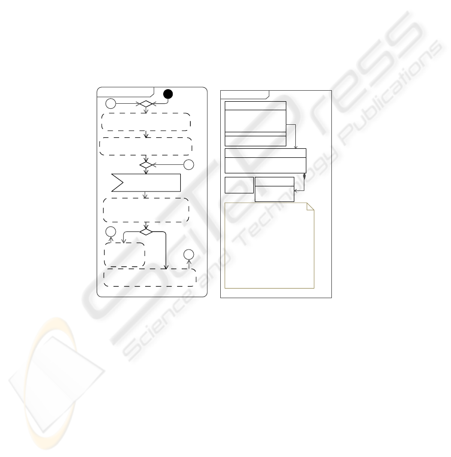
Integrating Use Case Realizations. The functionality of a system can be considered
as a set of use cases. For a precise specification of the entire functionality we need mod-
els that capture the control flow of the entire use case set. For example, the following
combination of models and a new semantics are used in [10] for a precise specification
of use case scenarios: an extended UML activity diagram in which the nodes are use
cases, for each use case a new activity diagram (interaction overview diagram) is used
where the nodes are scenarios, and each scenario is described using an interaction dia-
gram. We cannot follow such an approach because fUML does not include interaction
diagrams and interaction overview diagrams.
We need a similar integration mechanism for use case realizations. One or more
active classes may be used to integrate the entire functionality of the system. Their
classifier behaviours must coordinate other active objects (use case realizations) using
synchronization operations. For example, for integrating the entire system behaviour of
our word guessing game, a
Scramble
active class is introduced in Figure 2. The activity
presented in Figure 2 represents the classifier behaviour of
Scramble
.
83
3 Scenario Description
This section describes the concrete textual syntax for representing the scenarios of a
use case. A textual editor helps developers to write the scenarios in the context of an
active class which is the realization of the use case. As a result, an activity (which
is the classifier behaviour of the active class) and a corresponding activity diagram are
generated according to the fUML abstract syntax. Figure 2, 3, and 4 show these artifacts
for the case study introduced in the previous section.
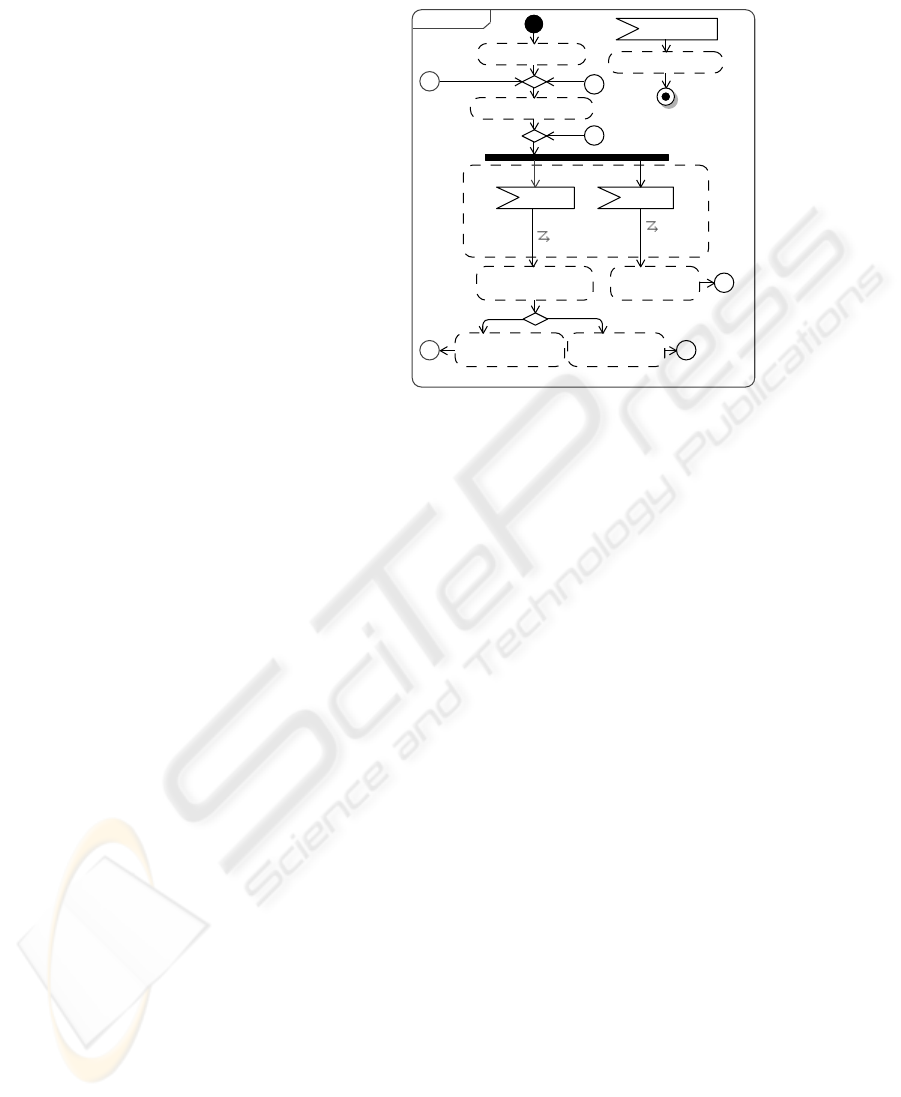
Basic
1 Display the word list
2 Set edited word to a new word
3 Accept save edited word
4 Persist edited word
5 Rejoin at 1
Alternatives
3a Accept cancel editing
3a.1 Rejoin at 2
3b Accept edit word
3b.1 Set edited word to
the selected word
3b.2 Rejoin at 3
4a Invalid data
4a.1 Set feedback to
'invalid data'
4a.2 Rejoin at 3
*a Accept play
*a.1 Start play
*a.2 Finish
Administeractivity
3 Save
edited word
3a Cancel
editing
3b Edit
word
2 Set edited word to a new word
4a.1 Set feedback to 'invalid data'
1 Display the word list
4 Persist edited word
3b.1 Set edited word
to the selected word
*a.1. Start play
*a. Play
A
C
B D
B
D
A
C
4a Invalid data
Fig.3. Administer Use Case.
The statements must be written on separate lines using keywords that have a distin-
guished meaning. The lines are numbered accordingto the templates used for specifying
use cases. The semantics is specified via the mapping of this concrete surface notation
to the fUML abstract syntax which is formally defined.
An input action is specified in the form “accept
signal event
”, where accept is a
keyword and
signal event
represents the receipt of an asynchronous signal instance. An
input action is mapped to an accept event action with the specified signal event. When
this statement is executed, the thread of execution is suspended, waiting for the receipt
of an instance of the
signal event
. When such a receipt triggers the accept statement, it
completes its execution, and further execution on its thread can continue.
Output and computation actions are specified using sentences written in natural
language. They are mapped to structured activity nodes which will be later detailed by
the developer.
Exception handling actions are of two types: alternatives to a user (input) action
and alternatives to a system (output or computation) action. An alternative to a user
action can be modelled using accept event actions and structured activity nodes or in-
84
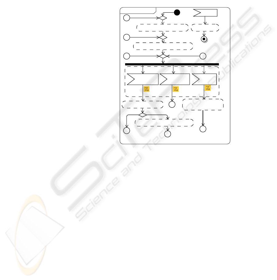
Basic
1 Set score to zero
2 Set scrambled word
3 Accept guess
4 If attempt is equal to current word,
4.1 Increase score by
word points
4.2 Rejoin at 2
Else
4.3 Decrease score by one
4.4 Rejoin at 3
Alternatives
3a Accept pass
3a.1 Decrease score by three
3a.2 Rejoin at 2
*a Accept administer
*a.1 Start administer
*a.2 Finish
activity Play
3 Guess 3a Pass
2 Set scrambled word
4 Attempt is equal to
the current word
*a.1 Start administer
4.1 Increase score
by word points
1 Set score to zero
*a Administer
4.3 Decrease
score by one
3a.1 Decrease
score by three
C
D
D
B
B C
[false]
[true]
Fig.4. Play Use Case.
terruptible activity regions - but the latter is not part of fUML. An alternative
D
to a
user action
B
can be modelled using a structured activity node which contains two ac-
cept event actions:
B
and
D
. Because the user may trigger any of these actions we can
model
B
and
D
with no incoming flows, so both will be enabled when the structured
node is executed. When the user triggers one of these actions, then we should disable
the other action. So, we must finish the execution of the structured node after both
B
and
D
actions and then propagate the control flow outside the structured activity node.
But this solution may produce concurrency problems.
An alternative
D
to a user action
B
is specified as an input action within the alter-
natives part. This statement is mapped to an interruptible activity region that surrounds
B
and
D
and a fork node which enables both actions. Two interrupting edges are used
from
B
and
D
to actions defined outside the interrupting region. When the user triggers
one of these actions, only the token which traverse the interrupting edge will be offered
and all the other tokens will be consumed by the interruptible region. Figure 5-b shows
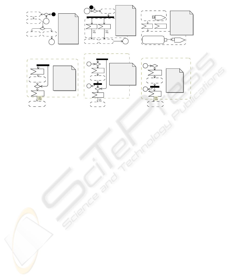
details about these mappings. The alternatives for step 3 in Figures 3 and 4 are mapped
according to these rules.
An alternativeto a system action is mapped to a decision node as Figure 5-a shows
(see also step 4a of Figure 3). The decision input flow and the required guards on control
flows will be later established when the scenario will be implemented.
An alternative input action that can be triggered at any time is mapped to an
accept event action defined with no incoming flows (see the alternatives *a in Figures
5-c, 3, and 4). When an activity starts, a control token is placed at each action that
has no incoming edges, so this alternative is enabled at startup. Moreover, an accept
event action with no incoming flows remains enabled after it accepts an event, so this
alternative remains enabled after an event is accepted.
Developers may define if statements for clarifying the scenarios of a use case. For
example, step 4 of
Play
presented in Figure 1 says that the system must check the at-
85
(a) Alternative to a system action
1 A
2 B
2a.1 D3 C
2a2
2a2
Basic
1 A
2 B
3 C
Alternatives
2a Invalid data
2a.1 D
2a.2 Rejoin at 1
Invalid
data
(b) Alternative to an accept event action
2a D2 B
3 C 2a.1 F
1 A
2a2
2a2
Basic
1 A
2 Accept B
3 C
Alternatives
2a Accept D
2a.1 F
2a.2 Rejoin at 1
(c) Send signals and accept events
3 Send C
<<readSelf>>
result
C
target
1 Send A to object
A
target
*a C2 B
Basic
1 Send A to object
2 Accept B
3 Send C
Alternatives
*a Accept C
2 B
1 A
3 C
1 Accept A
2 B
Optional 1-2
3 Accept C
4 D
(d) Optional sequence
4 D
2. B
1. A
3 C
A
A
(e) Sequence which may repeat
4 D
1 Accept A
2 B
Optional repeat 1-2
3 Accept C
4 D
2. B
1. A
3 C
A
A
1 Accept A
2 B
Repeat 1-2
3 Accept C
4 D
(f) Sequence which has to repeat
4 D
Fig.5. Textual Syntax Mappings.
tempt and adjust the score by increasing or decreasing the score, then steps 2-4 are
repeated. More precisely, if the score is increased, then a new word must be set (rejoin
at 2), otherwise a new attempt is required (rejoin at 3). Because this decision repre-
sents an important contribution to the control flow, it is recommended to be captured as
part of the basic flow (see Figure 4). The keywords if and else are used for specifying
this statement, the else clause being optional. The statement is mapped to a structured
activity node which represents the specified condition and a decision node which will
receive the result of the condition as a decision input flow.
A rejoin action is used to specify arbitrary cycles. This statement is mapped to a
control flow towards a merge node placed before the specified rejoin point. The figures
presented in this article split this control flow using labels. Splitting the control flow
helps developers to analyze complex scenarios. It is important to note that the rejoin
point must refer to the same base interaction course [6]. Otherwise, the descriptions
would follow harmful goto semantics, discouraged since the beginning of the structured
programming era. Moreover,this constraint helps us to generate structured code starting
from use case realizations.
The following actions can be used for integrating use case realizations: starting
and finishing the behaviour of an active class, and sending signals between active ob-
jects. “Start
active object
” is used to create an active object and to start its classifier
behaviour. This action is mapped to a create object action followed by a start object
behaviour action, both actions defined within a structured activity node. “Finish” is
used to finish the execution of an active object and is mapped to an activity final node.
Signals can be sent using the syntax “send
signal
to
destination
” (where
destination
is
optional). This statement is mapped to a structured activity which contains a send sig-
nal action - see Figure 5-c. The inclusion relationship between use cases can be realized
using these operations.
86
Other types of selection actions are: optional sequence, sequence which may repeat,
and sequence which has to repeat. The syntax for these statements and the mappings
to fUML abstract syntax are presented in Figure 5-d–f. Interuptible activity regions are
used for all these situations.
4 Scenario Implementation
If the scenarios of a use case are captured according to the previous section, then an
activity diagram is generated, the major benefit of this approach consisting in the au-
tomatically generated control flow. Now developers must implement the actions based
on an established architecture and using an action language. As a result, an executable
platform-independent model will be created. Running this model helps developers to
validate the system behavior. Finally, completed code may be generated towards some
existing platform specific frameworks.
Administeractivity
4a.1 Set feedback to 'invalid data'
feedback := 'invalid data'
2 Set edited word to a new word
editedWord := new Word()
1 Display the word list
words := repository.getWords()
4 Persist edited word
def result: Boolean :=
repository.persist(editedWord)
3 Save edited word
Save()
feedback :=
'word saved'
resut
A
B
B
A
4a Invalid
data [false]
[true]
detailed design[ ]
+getWords() : Word [0..*]
+persist( word : Word ) : Boolean
WordRepository
-words : Word [0..*]
-editedWord : Word [0..1]
-feedback : String [0..1]
Save()
Administer
-value : String
-points : Integer
Word<<signal>>
Save
GENERATED CODE:
init() {
words := repository.getWords();
editedWord := new Word();
}
save() {
if (repository.persist(editedWord)) {
feedback := 'word persisted';
init();
}
else feedback := 'invalid data';
}
-repository1
-words
0..*
Fig.6. Administer - Basic Flow and the Alternative 4a.
Currently, there is no standardized concrete syntax for a fUML based action lan-
guage, and OMG issued a Request for Proposal (RFP) for a concrete syntax [11]. In
this section we use our recently introduced fUML based action language [12]. When
the standardized action language will be available, we will align our action language to
the standard. Due to space limitations we only present the major decisions that must be
taken. Figure 6 illustrates the implementation of two scenarios of
Administer
based on
the architecture presented in Figure 2.
The computation actions are implemented as fUML statements defined in the con-
text of structured activity nodes. The output actions must set values to the properties of
the active class. If the input actions (accept event actions) carry data, then properties are
added to the corresponding signals in order to capture the data. The decision input flow
87

must be established for each decision node, then the guards must be written according
to that decision input.
Code generation towards structured programming languages is enabled by the con-
straint imposed on rejoin actions (rejoin points must refer to the same base interaction
course). A method described using structured statements can be generated for each sce-
nario (see
init
and
save
methods presented by the note of Figure 6).
5 Related Work
The method presented in the current work refers to a simple, constructive and prag-
matic transition from the problem space to the solution space. Recently, two simple and
constructive methods have been proposed, both in the general context of system engi-
neering: the pragmatic system modelling approach of Weilkiens [13] which uses the
Systems Modelling Language [14], and the behaviour engineering method of Dromey
[15] which uses nonstandard graphical representations. Both these approaches are ap-
proapriate to reactive systems, while our approach is tailored to algorithmic/data in-
tensive systems. Our method proposes a convenient concrete textual syntax to write
the control flow for use case realizations, while the above mentioned approaches pro-
pose different graphical representations which are not easily created for data intensive
systems.
Our proposed approach for integrating use case realizations is similar to that pro-
posed in [10]. Both use UML activities for defining use case integration, but our ap-
proach refers to PIMs while the latter refers to Computation IndependentModels (CIMs).
Again, the latter approach does not propose a convenient (pragmatic) approach based
on concrete textual representations.
Other contributions for requirements translation and integration were made in the
context of feature-oriented software development (FOSD) and Requirements Driven
Software Development [16, 17]. However, requirements translation and integration in
the context of FOSD and MDA/UML remain open issues (see the overview [18]), and
the requirements integration in the latter case does not reduce the pressure on our short-
term memory capacity.
6 Conclusions and Further Work
This article presented a pragmatic approach for the transition from requirements to de-
sign such that completed code towards platform specific frameworks may be generated.
A concrete textual syntax was presented which generates the control flow of use case
realizations in the context of fUML. A project is currently underway to implement the
techniques presented in this article.
As future work we intend to investigate the use of these techniques for defining
prototypes as CIMs. In this respect, a facility for prototyping user interface elements
and associating them with use cases is needed.
88

Acknowledgements
This work was supported by the grant ID 546, sponsored by NURC - Romanian Na-
tional University Research Council (CNCSIS).
References
1. Jacobson, I., Christerson, M., Jonsson, P., Overgaard, G.: Object-Oriented Software Engi-
neering: A Use Case Driven Approach. Addison-Wesley (1992)
2. Smialek, M.: Accommodating informality with necessary precision in use case scenarios.
Journal of Object Technology 4 (2005) 59–67
3. OMG: MDA Guide Version 1.0.1. (2003) omg/03-06-01.
4. OMG: Semantics of a Foundational Subset for Executable UML Models. (2008) ptc/2008-
11-03.
5. Cockburn, A.: Writing Effective Use Cases. Addison-Wesley (2000)
6. Metz, P., O’Brien, J., Weber, W.: Specifying use case interaction: Types of alternative
courses. Journal of Object Technology 2 (2003) 111–131
7. Williams, C., Kaplan, M., Klinger, T., Paradkar, A.: Toward engineered, useful use cases.
Journal of Object Technology 4 (2005) 45–57
8. Adolph, S., Bramble, P., Cockburn, A., Pols, A.: Patterns for Effective Use Cases. Addison-
Wesley (2002)
9. Mellor, S.J., Balcer, M.J.: Executable UML: A Foundation for Model-Driven Architecture.
Addison Wesley (2002)
10. Whittle, J.: Precise specification of use case scenarios. In: FASE’07: Proceedings of the
10th international conference on Fundamental approaches to software engineering, Berlin,
Heidelberg, Springer-Verlag (2007) 170–184
11. OMG: Concrete Syntax for a UML Action Language - Request For Proposal. (2008) ad/08-
08-01.
12. Lazar, C.L., Lazar, I., Motogna, S., Parv, B., Czibula, I.G.: Using a fUML Action Language
to Construct UML Models. In: 11th Int. Symp. SYNASC. (2009) (To appear).
13. Weilkiens, T.: Systems Engineering with SysML/UML. Morgan Kaufmann Publishers,
Eslsevier (2008)
14. OMG: Systems Modeling Language. (2008) http://www.omgsysml.org/.
15. Dromey, R.G.: Climbing over the ”No Silver Bullet” Brick Wall. IEEE Software 23 (2006)
118–120
16. Kaindl, H. et al: Requirements specification language definition. ReDSeeDS Project (2009)
www.redseeds.eu.
17. Drazan, J., Mencl, V.: Improved processing of textual use cases: Deriving behavior specifi-
cations. In: Proceedings of SOFSEM 2007. LNCS 4362, Springer-Verlag (2007) 856–868
18. Apel, S., Kastner, C.: An Overview of Feature-Oriented Software Development. Journal of
Object Technology 8 (2009) 49–84
89
