
DESIGN OF A PRESSURE SENSOR FOR MONITORING OF
POST-ENDOVASCULAR ANEURYSM REPAIR
A. T. Sepúlveda, A. J. Pontes, J. C. Viana, L. A. Rocha
Institute for Polymers and Composites/I3N, University of Minho, Braga, Portugal
Isa C. T. Santos
Instituto de Engenharia Mecânica e Gestão Industrial / Faculdade de Engenharia, Universidade do Porto, Porto, Portugal
F. Fachin, R. Guzmán de Villoria, B. L. Wardle
Department of Aeronautics and Astronautics, Massachusetts Institute of Technology, Cambridge, MA, U.S.A.
Keywords: Implantable pressure sensor, Aneurysms, Carbon nanotubes, Pressure sensor design.
Abstract: This paper introduces the design and fabrication process of a flexible pressure sensor for monitoring post-
endovascular aneurysm repairs (EVAR). Biocompatible flexible PDMS membranes with embedded aligned
carbon nanotubes (CNTs) with a conductivity of 11 S.m
-1
and elastic modulus of 2 MPa are used to build a
LC network for passive telemetry readout-out. The pressure sensor has a modelled sensitivity 14fF/mmHg
for a pressure range between 6-47 mmHg, in agreement with the required application. The pressure sensor,
with a 250 µm thickness and total area of 1 cm
2
, will be contained within the stent-graft and used to
measure the pressure inside the aneurysm sac to detect complications related to the EVAR procedure.
1 INTRODUCTION
An aneurysm can be defined as a permanent and
irreversible localized dilatation of an artery, having
at least a 50% increase in diameter compared with a
normal one. Aneurysms can appear anywhere but
they most commonly occur in the aorta, as well as in
arteries located at the base of the brain and in the
legs.
Two treatments are currently available for the
treatment of aneurysms: conventional surgical repair
(open surgery) (Myers, Devine, Barras and Self,
2001) and endovascular aneurysm repair (EVAR)
(Parodi, Palmaz, and Barone, 1991). The first
involves making a relatively large incision in the
abdomen and inserting a prosthetic graft to replace
the damaged section of the aorta. This procedure can
also be performed laparoscopically, either by hand-
assisted laparoscopic surgery or total laparoscopic
surgery. EVAR is a minimally invasive procedure in
which a stent-graft is guided from the femoral artery
to the affected artery segment in order to prevent
wall rupture, thereby shielding the aneurysm from
the blood pressure. This treatment is usually
associated with less physiological derangement,
lower morbidity and mortality, and more rapid
recovery than open surgery (Chuter, Parodi, and
Lawrence-Brown, 2004) but regular
monitoring/surveillance to detect and prevent
complications such as graft migration, stent fracture,
endoleaks, enlargement of the aneurysm sac, and
abdominal aortic aneurysm AAA rupture are
required (Katzen and MacLean, 2006) after the
procedure.
Comparing both approaches, EVAR is preferable
as it is less stressful, it significantly reduces
systemic complications (Rutherford and Krupski,
2004), and it has both lower costs associated with
inpatient stay and less (or no) need for intensive care
facilities during recovery (Myers et. al. 2001,
Hayter, Bradshaw, Allen, Guduguntla and Hardman,
2005). The durability of open surgery, established
with long-term follow-up studies, is excellent
(Rutherford and Krupski, 2004), so good that there
14
T. Sepúlveda A., J. Pontes A., C. Viana J., A. Rocha L., C. T. Santos I., Fachin F., Guzmán de Villoria R. and L. Wardle B..
DESIGN OF A PRESSURE SENSOR FOR MONITORING OF POST-ENDOVASCULAR ANEURYSM REPAIR.
DOI: 10.5220/0003127400140022
In Proceedings of the International Conference on Biomedical Electronics and Devices (BIODEVICES-2011), pages 14-22
ISBN: 978-989-8425-37-9
Copyright
c
2011 SCITEPRESS (Science and Technology Publications, Lda.)

is little or no requirement for long-term surveillance,
in contrast with EVAR whose current results suggest
that there is a need for increased surveillance and re-
intervention (Hayter et al., 2005, Michaels, Drury,
and Thomas, 2005, Greenhalgh, 2005). Considering
the longer life expectancies and the rising public
expectations for quality of life, the costs associated
with follow-up can jeopardize EVAR’s
effectiveness.
The current surveillance protocol involves
imaging at 1, 6, and 12 months after the procedure,
and thereafter, on an annual basis (Milner, Kasirajan
and Chaikof, 2006). In order to reduce and even
eliminate these exams, new surveillance
technologies are being investigated, with the most
promising technique identified thus far being
remote pressure sensing (Milner et al., 2006).
Remote pressure sensing enables the measurement
of both the systolic and diastolic pressures within the
residual aneurysm sac at any given point in time.
Thus far, the Impressure Sensor (Remon Medical
Technologies, Israel) and the CardioMems
EndoSure Wireless AAA Pressure Sensor
(CardioMems, Inc, USA) have been evaluated for
abdominal aortic aneurysms (AAA) (Milner et al.,
2006, Springer, Günther, and Schmitz-Rode, 2007).
This work introduces a new pressure sensor for
endotension measurement. The focus is on the use of
a flexible substrate enabling the conformability of
the sensor to the stent-graft and thus the aorta.
Compared to currently available devices, this aspect
brings several advantagessince the sensor can be
attached to the stent-graft and delivered in a single
procedure (as oposed to the requirement of two
catheters for the CardioMems device) and it enables
the placement of more than one sensor (a sensor
cluster) contributing to a more comprehensive study
of post-EVAR aneurysm evolution (that is currently
not possible).
The contributions in this paper are divided in 5
sections. After an introduction to the topic, the
required sensor specifications are derived followed
by the development of an electro-mechanical
pressure sensor model. Next, a new fabrication
process for the realization of the flexible sensor is
introduced and finally some experimental results and
conclusions are presented.
2 SENSOR SPECIFICATIONS
Research on implantable pressure sensors is very
active and has been supported and justified by the
need of continuous pressure monitoring for patients
with congestive heart failure, as an early diagnostic
mechanism for some risk patients and for post-
EVAR surveillance (Receveur, Lindemans, and de
Rooij, 2007, Potkay, 2008). Implantable pressure
sensors are typically categorized into extra-arterial
blood pressure and intra-arterial blood pressure
(Potkay, 2008) devices. Extra-arterial pressure
sensors are placed around the blood vessel and
perform an indirect pressure measurement through
the wall or through the expansion and contraction of
the artery, requiring however an invasive surgical
procedure for their implant while the intra-arterial
devices are in contact with the blood stream, inside
of the blood vessels.
Potkay (2008) defined a set of requirements for
pressure sensors according to the problem to be
addressed. In the case of EVAR, the requirements of
the pressure sensor are shown in Table 1.
Table 1: Requirements for post-EVAR surveillance
(Potkay, 2008).
Characteristic Value
Measurement location
Between graft and
aneurysm wall
Typical values (mmHg) 20 to 90
Measurement range (mmHg) 20 to 250
Measurement resolution (mmHg) 1
Measurement absolute accuracy
(mmHg)
5
Signal bandwidth (Hz) 0 to 80
Arterial diameter (mm) 15 to 40
After stent-graft placement, the aneurysm sac
gets depressurized and the pressure drops down to a
few mmHg. A numerical study performed by Li and
Kleinstreuer (2006) shows that after EVAR the
pressure inside the aneurysm sac is around 12% of
the current luminal pressure. Therefore, if one wants
to sense the luminal pressure value (which ranges
typically between 60 – 160 mmHg) through the
aneurysm sac pressure, the sensor must be able to
measure pressures between 6-16 mmHg with a
resolution of 0.1 mmHg. In addition, the sensor
needs a high dynamic range in order to detect stent-
graft complications (in this case the sac gets
pressurized and pressure increases to the luminal
pressure values).
2.1 Telemetry System
The pressure monitoring system under development
uses a passive telemetry system, based on an
DESIGN OF A PRESSURE SENSOR FOR MONITORING OF POST-ENDOVASCULAR ANEURYSM REPAIR
15
implantable LC resonant network, for the external
readout of the pressure sensor signal. The use of
passive telemetry in implantable medical devices is
well established (Mokwa, 2007) and enables the
realization of active implants with no power
constraints. A circuit representation of the sensor
system and external reader, using the transformer
model (parasitic capacitance is not included), is
presented in Figure 1. The components in the sensor
are modelled as passive elements: a variable
capacitor C
s
whose value changes with the applied
pressure, connected to an inductor L
s
, resulting in a
parallel resonant circuit. The schematic
representation in Figure 1 includes also the resistors
R
p
and R
s
which model the parasitic elements
associated with the inductors L
p
and L
s
and the
capacitor C
s
.
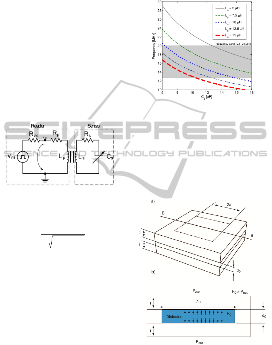
Figure 1: Telemetry circuit.
If the transformer is replaced by its T model, the
following expression for the oscillating frequency is
obtained:
()
2
1
21
osc
ss
f
kLC
π
=
−
,
(1)
where k represents the coupling coefficient of the
transformer.
The system oscillation frequency was chosen to
operate in the frequency band from 12.5 to 20.0
MHz, allocated specifically for medical applications.
This frequency band presents additional advantages,
unlike low operational frequencies, since the
inductors and capacitors require small dimensions
and therefore small sensors’ area. Assuming a k =
0.06 (expected value for a distance of 5cm between
the sensor system and the external reader) Equation
1 is used to assess the capacitance and inductor
values required for the chosen frequency band. The
results are presented in Figure 2.
Figure 2: Telemetry system oscillating frequency vs.
capacitance for several inductor values.
A detailed analysis as that shown in Figure 2
reveals that for inductors ranging from 5 to 15 μH,
the capacitive changes should be between 5 and 18
pF to be within the chosen frequency band. The
external reader is expected to have a resolution
better than 1 kHz. If an inductor of 12.5 μH is used
during the design of the sensor, the capacitive
pressure sensor changes should be within the
interval 5-12 pF for pressure variations between 6 to
120 mmHg.
Figure 3: Schematic of the pressure square (sidelength =
2a) sensor a) 3D view and b) section cut B-B.
BIODEVICES 2011 - International Conference on Biomedical Electronics and Devices
16

3 PRESSURE SENSOR MODEL
The proposed pressure sensor is based on two
square-plate (diaphragm) electrodes separated by a
dielectric (air, at a pressure P
0
). Changes on the
outside pressure (P
out
) deform the square plate and
consequently generate a capacitive change. A
schematic of the square platform (sidelenght of 2a)
pressure sensor is shown in Figure 3.
The sensor involves two coupled domains,
mechanical and electrical, that define the sensor
behaviour. An analysis of the behaviour of the two
domains leading to the final model is performed
next.
3.1 Mechanical Domain
The starting point to build the analytical model is the
generic square diaphragm described in Figure 4
where a is the sidelength, t is the thickness and y
0
is
the deflection. The diaphragm is clamped at the
edges.
For a clamped diaphragm under a uniform load
(like pressure), the angle of deflection, ϕ, can be
defined as equal to zero at the center (r = 0) and at
the edge (r = a) of the diaphragm. For these
boundary conditions, the deflection of a square
diaphragm under a pressure load can be modelled by
(Chau and Wise, 1987):
3
4
00
0
24 3
4.20 1.58
(1 )
out
yy
Et
PP
t
at
υ
⎡⎤
−= +
⎢⎥
−
⎣⎦
(2)
where
υ
is the Poisson’s ratio, E is the Young’s
modulus, and
Δ
P=P
0
-P
out
is the pressure load.
Figure 4: Generic model for a deflectable diaphragm.
Equation (2) allows the calculation of the
deflection at the center of the diaphragm for a given
pressure load, but, the deflection along the
diaphragm is still required to model the capacitive
changes due to gap variation. The complexity of the
mechanical deflection model makes it difficult to
obtain a closed form solution for the deflection of
the diaphragm from the center to the edges.
Assuming large deflections (expected due to the
elasticity and low Young’s Modulus of the flexible
membranes) a circular deflection is considered and
introduced here as:
0
() sin arccos
r
yr y
a
⎛⎞
⎛⎞
=
⎜⎟
⎜⎟
⎝⎠
⎝⎠
(3)
Although the profile given by equation (3) might
introduce some errors, it enables the calculation of a
closed form expression for the changes in the
capacitor.
3.2 Electrostatic Domain
A capacitor is an electronic component with two
electrodes that are separated by a dielectric. For the
simple case of a parallel plate capacitor, and in the
absence of displacements, the model for the
capacitor is:
0
0
r
wl
C
d
εε
= ,
(4)
where
ε
0
is the permittivity of free space
(
8.8546x10⁻¹² F/m),
ε
r
is the relative permittivity, w
and
l are the width and length of the capacitor
electrodes, and
d
0
is the gap between the electrodes.
Figure 5: Area of a circular diaphragm vs. square
diaphragm.
Since the capacitive sensor proposed here uses
diaphragm electrodes with a complex bending
profile, integration over the effective area of the
electrodes is required to compute the total
capacitance:
0
0
2(,)
r
Cdxdy
ddxy
εε
=
+
∫∫
,
(5)
where d(x,y) is the distance between electrodes due
to the diaphragm bending at position x, y. The
integration of the bending profile of a square
diaphragm is a complex exercise, and therefore, an
interesting solution is to consider a circular
diaphragm and use integration along the radius to
DESIGN OF A PRESSURE SENSOR FOR MONITORING OF POST-ENDOVASCULAR ANEURYSM REPAIR
17

compute the capacitance (see Figure 5). With this
simplification and replacing d(x,y) in equation (5)
for y(r) yields for the capacitor model:
()
(
)
2
0
00
00
2
00 00 0
0
2
0
2 sin arccos
ln( ln( 2 ) 2
2
a
r
d
dr
Crdrd
r
dy
a
ad d d y y
C
y
π
εε
θ
π
εε
==
⎛⎞
⎛⎞
+
⎜⎟
⎜⎟
⎝⎠
⎝⎠
−++
=
∫∫
(6)
The total capacitance, considering the areas not
covered by the circular diaphragm, and assuming an
average bending at the corners of 8% of the total
bending is:
2
0
00
(4 )
0.08
total d r
a
CC
dy
π
εε
−
=+
+
(7)
4 FABRICATION PROCESS
Given the characteristics of the application (the
sensor will be attached to the stent-graft) the
capacitive sensor must be foldable, extremely
flexible and characterized by a very small profile. In
addition, the technology should be simple and
biocompatible. Silicon based microtechnologies are
widely used in implantable medical devices
(Receveur et al., 2007), but due to the application
specifications, a new fabrication process is being
developed.
The proposed fabrication process uses aligned
carbon nanotubes (CNTs) to build the conductive
elements, namely the inductor and the capacitor
electrodes. The CNTs are embedded in a flexible
substrate of polydimethylsiloxane (PDMS), a
transparent, nontoxic and biocompatible silicone
elastomer.
The fabrication process flow for the development
of the flexible pressure sensor is schematically
presented in Figure 6. Acrylic moulds are produced
by CNC milling (Figure 6a) for posterior fabrication
of the PDMS membranes. This technique has low
costs and fast production times, but it is associated
with poor dimensional control (dimensions less than
50μm are difficult to achieve).
The electrical components (capacitor electrodes
and inductor) are based on aligned CNTs, as shown
in Figure 6b. Chemical vapour deposition (CVD) is
used to grow forests or “carpets” of vertically-
aligned CNTs (Bello, Hart, Ahn, Hallock,
Yamamoto, Garcia, Ellenbecker and Wardle, 2008).
Figure 6: Fabrication process flow for the development of
a flexible pressure sensor with aligned-CNT/PDMS
nanocomposites.
A silicon substrate with patterned Fe/Al
2
O
3
catalyst
is placed on a horizontal quartz tube furnace at
atmospheric pressure at 750 ºC (Hart, and Slocum,
2006) for the CNT growth. This method has the
advantage of allowing growth of high purity, high
yield and vertically aligned morphology. Next, the
CNTs are embedded into the polymer matrix
(PDMS). This step is schematically represented in
Figure 6c. The substrate is placed against the
moulds, and the PDMS is introduced in the cavities
through a hole, followed by the curing of the
elastomer.
The flexible pressure sensor is composed of three
thin layers, with the top and bottom layers defining
the inductor and the electrodes, and the middle one
defining the dielectric (air). This configuration
requires bonding of PDMS membranes. Eddings,
Johnson and Gale (2008) tested five different
bonding techniques and the highest reported bond
strength was obtained for both partial curing and
uncured PDMS adhesive techniques. The latter
approach has proven successful in our work as well,
and will be used for future experimentation.
5 RESULTS AND DISCUSSION
The key step of the fabrication process is the CNT-
PDMS impregnation and respective mechanical and
electrical properties (required for the sensor design).
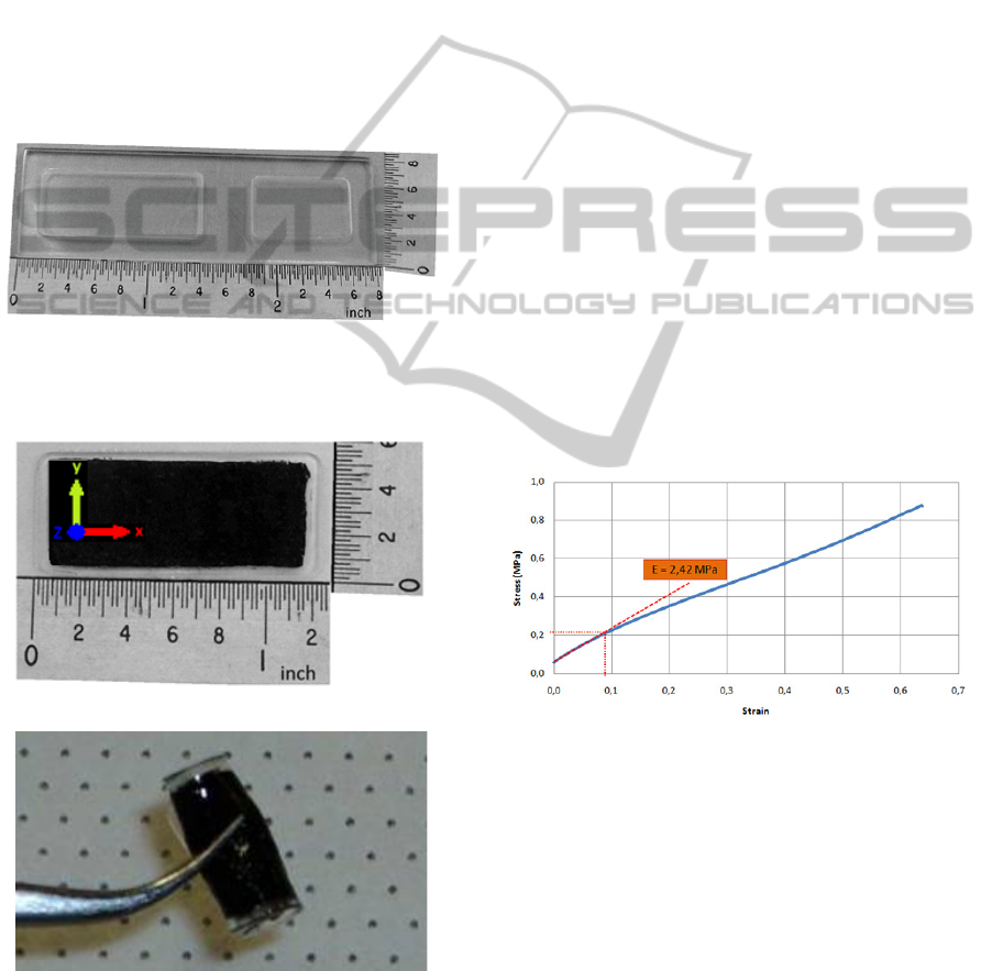
Acrylic moulds have been fabricated (Figure 7), and
are being used to build the PDMS flexible
membranes with embedded CNTs (Figure 8).
BIODEVICES 2011 - International Conference on Biomedical Electronics and Devices
18
Aligned CNTs are oriented in the out-of-plane (or
normal to the wafer plane) direction such that the
polymer nanocomposite can be presumed
transversely isotropic, i.e., isotropic in the plane of
the sensor. Furthermore, the modulus enhancement
due to CNTs is likely minimal as the long axis of the
CNTs are oriented perpendicular to the loading
direction, such that the PDMS polymer dominates
the response. Recent work has shown significant
increase in modulus due to aligned CNTs in polymer
(PDMS) (Ajayan et al., 2000) and epoxy (Cebeci et
al., 2009) in the CNT axis direction, but little
reinforcement effect in the transverse direction as
used here. This result is expected from composite
micromechanics analyses and experimental results.
Figure 7: Fabricated acrylic moulds for the production of
PDMS membranes.
a)
b)
Figure 8: PDMS membrane with embedded aligned CNTs
a) normal (the “z” axis corresponds to the direction of
CNTs) and b) folded.
5.1 Electrical and Mechanical
Characterization
Preliminary measurements of a series of PNC
samples (PDMS membranes with embedded CNTs)
indicate an electrical conductivity of 11.43 S.m
-1
with a standard deviation of 13.37 S.m
-1
. The
relatively high value of the standard deviation is
related to the manual process being used for the
membrane fabrication which gives origin to some
imperfections.
Some other samples where subject to mechanical
tests to obtain the elastic modulus and tensile
strength. The PDMS/CNTs specimens were
moulded into rectangular shapes with dimensions of
32 x 14 x 0.4 mm
3
(L x W x H), as shown in Figure
8a. The tensile tests were performed on a Zwick
Z010 machine with a 500 N load-cell and extension
rate of 1 mm/min for all specimens. Through the
measured stress-strain curve, both the elastic
modulus and tensile strength can be determined.
Figure 9 shows an exemplary stress-strain curve of
PDMS/CNTs membrane which has ~1% CNTs by
volume oriented perpendicular to the loading
direction. The tested membranes present an elastic
modulus of about 2.42 MPa (at the initial stage) and
rupture at around 0.87MPa. The pure PDMS has a
Young modulus of approximately 0.5 MPa.
Figure 9: Stress-Strain curve of a flexible PDMS
membrane with embedded CNTs.
5.2 Sensor Geometry
Equations (6) and (2) enable us to analytically
calculate the capacitance changes for a given applied
pressure on the sensor. An analytical model was
implemented using the two equations and was used
to design the sensor. The main concerns during the
design phase were related to the device thickness
(<=300 μm) and the capacitor total area (<=1.5
cm
2
).
DESIGN OF A PRESSURE SENSOR FOR MONITORING OF POST-ENDOVASCULAR ANEURYSM REPAIR
19

Table 2: Dimensions and material properties of the
pressure sensor.
Parameter Description Value
a radius 5 mm
d
0
distance between
electrodes
50 μm
P
0
Pressure of the sensor
cavity
8000 Pa
t diaphragm thickness 100 μm
E Elastic Modulus 2.42 MPa
υ
Poisson’s ratio 0.48
ε
r
relative permittivity 1
ε
0
permittivity of free space 8.854x10
-12
F/m
An important characteristic of the sensor
behaviour is the sensitivity dependence on the
dielectric cavity pressure (P
0
). If the last bonding
step is performed in a pressure controlled
environment, P
0
can be controlled which allows the
realization of sensors with different sensitivities and
dynamic ranges. Table 2 presents the defined sensor
dimensions taking into account that for this
application, the pressure range to be measured is
around 6-16 mmHg, while Figure 10 presents the
expected capacitance changes using the analytical
model.
In order to validate the model, a Finite Element
Model (FEM) was developed in ANSYS using a
coupled domain (mechanical and electrostatic)
approach. The developed FEM model uses initially a
structural physical domain that computes the
bending due to applied pressure. Then, the command
dvmorph is issued and the non-structural areas are
re-meshed (taking into account the displacement of
the diaphragm due to pressure applied). Finally, an
electrostatic physical domain is used to calculate the
capacitance. The comparative results are presented
in Figure 10. The deviations between models are due
to the assumptions made during the derivation of the
analytical model.
Figure 10: Capacitance changes due to external pressure
changes.
Figure 11a shows the bending of the diaphragm for
an external pressure of 6mmHg and Figure 11b the
stress on the membranes.
5.3 Discussion
The results obtained raise three main concerns
regarding the suitability of the realization of a
pressure sensor with passive telemetry using the
proposed technology. The first one is related to the
rather low conductivity of the PDMS membranes
with embedded CNTs. The low conductivity will
generate a rather high resistance of the inductor and
therefore the energy transferred inductively will be
dissipated in the resistor. Solutions to overcome this
problem are already being studied, and the use of
inkjet-printed conductive inks seems to be a good
candidate. Alignment of the continuous CNTs in the
conduction direction is another option, as much
higher conductivities have been reported for PNCs.
A second concern is the low capacitive value (1-
2pF) of the proposed sensor geometry. While the
capacitive changes are within the desirable values,
the total capacitor value is lower than the required
one (see section 2). This problem can be easily
overcome by placing a fixed capacitor in parallel
(using the middle PDMS layer as dielectric) in such
a way that the total capacitance value is within the
required values (5-12pF). PNC morphology changes
may also be used to engineer this quantity as with
electrical resistivity above.
Figure 11: Results from the FEM model a) bending and b)
von Mises stress contours.
BIODEVICES 2011 - International Conference on Biomedical Electronics and Devices
20

The third concern relates to the tensile strength
of the membranes. The measured rupture stress of
the samples (~0.87 MPa) is within the range of
stresses given by the FEM model. While the stresses
on the diaphragm are well below this value, the
stresses retrieved from the FEM model on the edges
of the diaphragm approach the membranes tensile
strength meaning that the devices can break during
operation. A solution to reduce the stress in the
edges could be to work on the mould in order to
avoid sharp edges (where stresses tend to
accumulate). Alternatively, one could try to increase
the tensile strength of the membranes by changing
the volume fraction and/or configuration of the
embedded aligned CNTs.
6 CONCLUSIONS
This paper introduces a new approach for the
pressure measurement within an aneurysm sac for
post-EVAR surveillance based on a highly flexible
pressure sensor. The pressure sensor is flexible and
thin so it can be placed on top of a stent-graft and
delivered during the EVAR procedure without the
requirement of an extra surgery step.
The characterization results of the new
introduced fabrication process are promising and
enable the realization of a pressure sensor that has
the required specifications (sensitivity and dynamic
range) for the application. Nevertheless, some
problems are foreseen that can jeopardize the final
implementation. This technology can find
applications in other fields such as e-textiles and
portable medical devices, opening the scope of the
current research.
The first sensor prototypes are under
development, and fully sensor characterization is
expected soon.
ACKNOWLEDGEMENTS
The first author wishes to thank FCT - Fundação
para a Ciência e Tecnologia, Portugal, for the
financial support provided by the grant SFRH/BD/
42922/2008. This work is supported by FCT under
the project MIT-Pt/EDAM-EMD/0007/2008. CNT-
based polymer composite materials were developed
with funding from Airbus S. A. S., Boeing, Embraer,
Lockheed Martin, Saab AB, Spirit AeroSystems,
Textron Inc., Composite Systems Technology, and
TohoTenax Inc. through MIT’s Nano-Engineered
Composite aerospace STructures (NECST)
Consortium.
REFERENCES
Ajayan, P. M., Schadler, L. S., Giannaris, C. and Rubio,
A. (2000), Single-Walled Carbon Nanotube–Polymer
Composites: Strength and Weakness. Advanced
Materials, 12, 750-753.
Bello, D., Hart, A. J., Ahn, K., Hallock, M., Yamamoto,
N., Garcia, E. J., Ellenbecker, M. J., Wardle, B. L.
(2008). Particle exposure levels during CVD growth
and subsequent handling of vertically-aligned carbon
nanotube films. Carbon, 46, 974-977.
Cebeci, H., Guzmán de Villoria, R., Hart, A. J., and B. L.
Wardle (2009). Multifunctional Properties of High
Volume Fraction Aligned Carbon Nanotube Polymer
Composites with Controlled Morphology. Composites
Science and Technology, 69, 2649-2656.
Chau, H.-L. and Wise, K. D. (1987). Scaling limits in
batch-fabricated silicon pressure sensors. IEEE Trans.
Electron Devices ED, 24, 850–858.
Chuter, T., Parodi, J. C. and Lawrence-Brown, M. (2004).
Management of abdominal aortic aneurysm: a decade
of progress. Journal of Endovascular Therapy,
11(Suppl II), S82-S95.
Eddings, M. A., Johnson, M. A., Gale, B. K. (2008).
Determining the optimal PDMS-PDMS bonding
technique for microfluidic devices. J. Micromech.
Microeng. 18, 067001.
Greenhalgh, R. M. (2005). Endovascular aneurysm repair
versus open repair in patients with abdominal aortic
aneurysm (EVAR trial 1): randomised controlled trial.
Lancet, 365(9478), 2179-2186.
Hart, J., Slocum, A. H. (2006). Rapid growth and flow-
mediated nucleation of millimeter-scale aligned
carbon nanotube structures from a thin-film cata-lyst.
Journal of Physical Chemistry B, 110, 8250-8257.
Hayter C. L., Bradshaw S. R., Allen R. J., Guduguntla M.
and Hardman D. T. (2005). Follow-up costs increase
the cost disparity between endovascular and open
abdominal aortic aneurysm repair. Journal of Vascular
Surgery, 42(5), 912-918.
Katzen, B. T. and MacLean, A. A. (2006). Complications
of endovascular repair of abdominal aortic aneurysms:
A review. CardioVascular and Interventional
Radiology, 29(6), 935-946.
Li, Z. and Kleinstreuer, C. (2006). Analysis of
biomechanical factors affecting stent-graft migration
in an abdominal aortic aneurysm model. J. of
Biomechanics, 39 (12), 2264-73.
Michaels, J. A., Drury, D. and Thomas, S. M. (2005).
Cost-effectiveness of endovascular abdominal aortic
aneurysm repair. British Journal of Surgery, 92, 960-
967.
Milner, R., Kasirajan, K. and Chaikof, E. L. (2006). Future
of endograft surveillance. Seminars in Vascular
Surgery, 19(2), 75-82.
DESIGN OF A PRESSURE SENSOR FOR MONITORING OF POST-ENDOVASCULAR ANEURYSM REPAIR
21

Mokwa, W. (2007). Medical implants based on
Microsystems. Meas. Sci. Technol., 18, R47-R57.
Myers, K., Devine, T., Barras, C., Self, G. (2001).
Endoluminal Versus Open repair for abdominal aortic
aneurysms. 2nd Virtual Congress of Cardiology.
Parodi, J. C., Palmaz, J. C. and Barone, H. D. (1991).
Transfemoral intraluminal graft implantation for
abdominal aortic aneurysms. Annals of Vascular
Surgery, 5(6), 491-499.
Potkay, J. A. (2008). Long term, implantable blood
pressure monitoring systems. Biomed Microdevices,
10, 379–392.
Receveur, R. A. M., Lindemans, F. W. and de Rooij, N .F.
(2007). Microsystems technologies for implantable
applications. J. Micromech. Microeng., 17, R50-R80.
Rutherford, R. B. and Krupski, W. C. (2004). Current
status of open versus endovascular stent-graft repair of
abdominal aortic aneurysm. Journal of Vascular
Surgery, 39(5), 1129-1139.
Springer, F., Günther, R. W. and Schmitz-Rode, T. (2007).
Aneurysm sac pressure measurement with minimally
invasive implantable pressure sensors: An alternative
to current surveillance regimes after EVAR?.
CardioVascular and Interventional Radiology, 31(3),
460-467.
BIODEVICES 2011 - International Conference on Biomedical Electronics and Devices
22
