
A MULTIMODAL BRAIN-ARM INTERFACE FOR OPERATION
OF COMPLEX ROBOTIC SYSTEMS AND UPPER LIMB MOTOR
RECOVERY
Michele Folgheraiter
1
, Elsa Andrea Kirchner
1,2
, Anett Seeland
1
, Su Kyoung Kim
1,2
Mathias Jordan
1
, Hendrik Woehrle
1
, Bertold Bongardt
1
, Steffen Schmidt
1
Jan Christian Albiez
1
and Frank Kirchner
1,2
1
German Research Center for Artificial Intelligence (DFKI), Robotics Innovation Center
Robert-Hooke-Strasse 5, D-28359 Bremen, Germany
2
University of Bremen, Robotics Lab, Robert-Hooke-Strasse 5, D-28359 Bremen, Germany
Keywords:
Haptic Interface, Bio-Inspired Design, Brain-Computer Interface, Wearable Exoskeleton, Support Vector
Machine, Adaptive Brain Reading Interface, Electroencephalogram, Lateralized Readiness Potential, Bere-
itschaftspotential.
Abstract:
This work introduces the architecture of a novel brain-arm haptic interface usable to improve the operation of
complex robotic systems, or to deliver a fine rehabilitation therapy to the human upper limb. The proposed
control scheme combines different approaches from the areas of robotics, neuroscience and human-machine
interaction in order to overcome the limitations of each single field. Via the adaptive Brain Reading Interface
(aBRI) user movements are anticipated by classification of surface electroencephalographic data in a mil-
lisecond range. This information is afterwards integrated into the control strategy of a wearable exoskeleton
in order to finely modulate its impedance and therefore to comply with the motion preparation of the user.
Results showing the efficacy of the proposed control approach are presented for the single joint case.
1 INTRODUCTION
Service robotics systems are becoming more and
more complex both from the manipulation and lo-
comotion capabilities point of view. This inevitably
brings new challenges for their control strategy, which
nowadays on the one hand is still lacking a complete
autonomy and on the other hand is constantly required
to accomplish the intention of the human that is inter-
acting or supervising the machine.
To improve the interaction between the machine
and the human it is therefore necessary to develop
proper interfaces that allow a bidirectional communi-
cation: namely interpret the will of the user and trans-
late it into a proper command for the robot, and reflex
to the user the perception of the environment that sur-
round the robot.
Exoskeleton interfaces for the upper and lower
limbs have gained increasing attention in the last
decade. They can be employed in a wide range of
applications: as master devices for teleoperation, as
haptic interfaces that mediate the interaction of the
user with virtual objects, as physiotherapy tools, or
as devices that enhance the strength of the user.
The ESA Exoskeleton (Schiele and van der Helm,
2006), developed at the European Space Agency, is an
example of upper limb interface equipped with 16 De-
grees Of Freedom (DOF), eight of which moved via
a tendon-based system. The device is intended to al-
low astronauts inside the International Space Station
(ISS) to teleoperate EUROBOT, a humanoid robot
that will support extravehicular activities (EVA). Al-
though some of the joints are not directly actuated, the
overall arm-exoskeleton system is fully controllable.
This is due to the parallel structure that is formed dur-
ing the interaction between limb and the device.
At the department of Electrical Engineering, Uni-
versity of Washington, a third generation dual-arm (7
+ 7 DOF) exoskeleton (Rosen et al., 2005) was devel-
oped on the base of anthropometric data. The system
150
Folgheraiter M., Andrea Kirchner E., Seeland A., Kyoung Kim S., Jordan M., Wöhrle H., Bongardt B., Schmidt S., Christian Albiez J. and Kirchner F..
A MULTIMODAL BRAIN-ARM INTERFACE FOR OPERATION OF COMPLEX ROBOTIC SYSTEMS AND UPPER LIMB MOTOR RECOVERY.
DOI: 10.5220/0003135501500162
In Proceedings of the International Conference on Biomedical Electronics and Devices (BIODEVICES-2011), pages 150-162
ISBN: 978-989-8425-37-9
Copyright
c
2011 SCITEPRESS (Science and Technology Publications, Lda.)

is fixed to the floor via a special frame; each arm has
seven single-axis revolute joints moved by cables and
pulleys that transmit the forces from the actuators lo-
cated in the robot base. A precise placement of the
joint singularities in the periphery of the workspace
guarantees high-force isotropy and avoids workspace
restrictions at the same time.
The SARCOS MasterArm (from SARCOS Inc.)
(Mistry et al., 2005) is a 7 DOF hydraulically actuated
arm-exoskeleton. The system is hung up by a fixed
platform and the user operates the device by holding
it at the most distal joint. The shoulder in this case
remains unconstrained, but is positioned such that the
three rotation axes of the exoskeleton approximately
intersect with the center of rotation of the articulation.
Another important field where exoskeletons can
bring significant benefits is represented by rehabilita-
tion. In particular the usage of robotic devices is suit-
able for the long-term therapy of patients with neu-
rodegenerative diseases or trauma-inflicted impair-
ments (Reinkensmeyer et al., 2001; Harwin et al.,
2006).
Robotic rehabilitation is expected to allow thera-
peutic interventions that are tailored to patients’ con-
ditions, enabling repeatable training curricula, objec-
tified assessment of progress, and can be used by pa-
tients independently. Neuro-plasticity, i.e., the reorga-
nization of tissue in the central nervous system (Har-
win et al., 2006), is a key motivation for robotic re-
habilitation. Stimulation of the sensorimotor system
with increased levels of proprioceptive input gener-
ated by robotic rehabilitation devices has been argued
(Reinkensmeyer et al., 2004) to yield higher levels of
functional recovery than those achieved by conven-
tional approaches in some studies.
The MANUS system, initially developed at MIT,
has been in daily operation since 1994 delivering
therapy to stroke patients at the Burke Rehabilitation
Hospital (Krebs et al., 2004). MANUS is a planar
module which provides two translational degrees-of-
freedom for elbow and forearm motion. The mod-
ule is portable and consists of a direct-drive five
bar-linkage SCARA (Selective Compliance Assem-
bly Robot Arm). The system has been commercial-
ized and is currently marketed by Interactive Motion
Technologies Inc.
ARMin II is the second prototype of a robot for
arm therapy applicable to train activities of daily liv-
ing in the virtual reality, developed at ETH Zurich.
ARMin II has a semi-exoskeletal (grounded) struc-
ture with seven active degrees of freedom, five ad-
justable segments to fit different user sizes, and is
equipped with position and force sensors. The sys-
tem is back-drivable and enables the implementation
of impedance or admittance-based patient cooperative
control strategies via analysis of force and torque sen-
sor data.
The analysis of brain activity for the purpose of
rehabilitation is mainly realized by the application of
Brain-Computer Interfaces (BCIs) to restore the abil-
ity to communicate, manipulate, or move (Wolpaw
et al., 2002). One of the first BCIs was based on
the detection of the ERP P300 (Farwell and Donchin,
1988) which is elicited in the brain whenever a seldom
and important stimulus is processed (Squires et al.,
1975). Similarly, brain activity related to movement
preparation or the imagination of movement is used
to directly control computer programs, machines, or
protheses by the use of BCIs. For that, analysis fo-
cuses on the detection of event-related synchroniza-
tion (ERS) or desynchronization (ERD) in certain fre-
quency bands of the EEG (Leeb et al., 2006) or ERPs
that are related to movement preparation (Blankertz
et al., 2006), like the BP or the LRP (Kornhuber and
Deecke, 1965; Masaki et al., 2004).
Movement related potentials (such as BP/LRP),
evoked during voluntary movement tasks, have been
analyzed by several BCI research groups. For in-
stance, Blankertz et al. showed that it is possible to
distinguish single trials of left vs. right finger move-
ment in a self-paced keyboard typing task (Blankertz
et al., 2003; Krauledat et al., 2004). The data pro-
cessing for every channel is done first by emphasizing
the end of each window of length 1280 ms sampled at
100 Hz with a cosine function of the form
w(n) := 1 − cos(
n · π
128
) for n = 0, . . . , 127, (1)
since for a fast detection of the LRP always the last
points in time of the extracted signal are most im-
portant. After that, a frequency filtering with a pass-
band from 0.4 to 3.5 Hz and a subsampling to 20 Hz
is applied. Then the last 4 data samples in each win-
dow are used as features and are classified by Regu-
larized Fisher Discriminant. For a pseudo-online test
in a feedback session, where subjects see the classifier
output as a moving trace on a screen, sliding windows
are extracted every 40 ms.
The data set generated by Blankertz et al. was also
published for the NIPS*2001 (BCI) post-workshop
Competition 2001 (Sajda et al., 2003) and analyzed
by several other authors with different approaches.
For example, Pires et al. filtered below 5 Hz and gen-
erated features using a regression model. These fea-
tures were then classified with Linear Discriminant
Analysis (Pires et al., 2007). In contrast Li et al. used
the amplitude difference between left and right elec-
trodes as features, after a filtering from 0 to 3 Hz. Sub-
sequently spatial filtering is applied and features are
A MULTIMODAL BRAIN-ARM INTERFACE FOR OPERATION OF COMPLEX ROBOTIC SYSTEMS AND UPPER
LIMB MOTOR RECOVERY
151
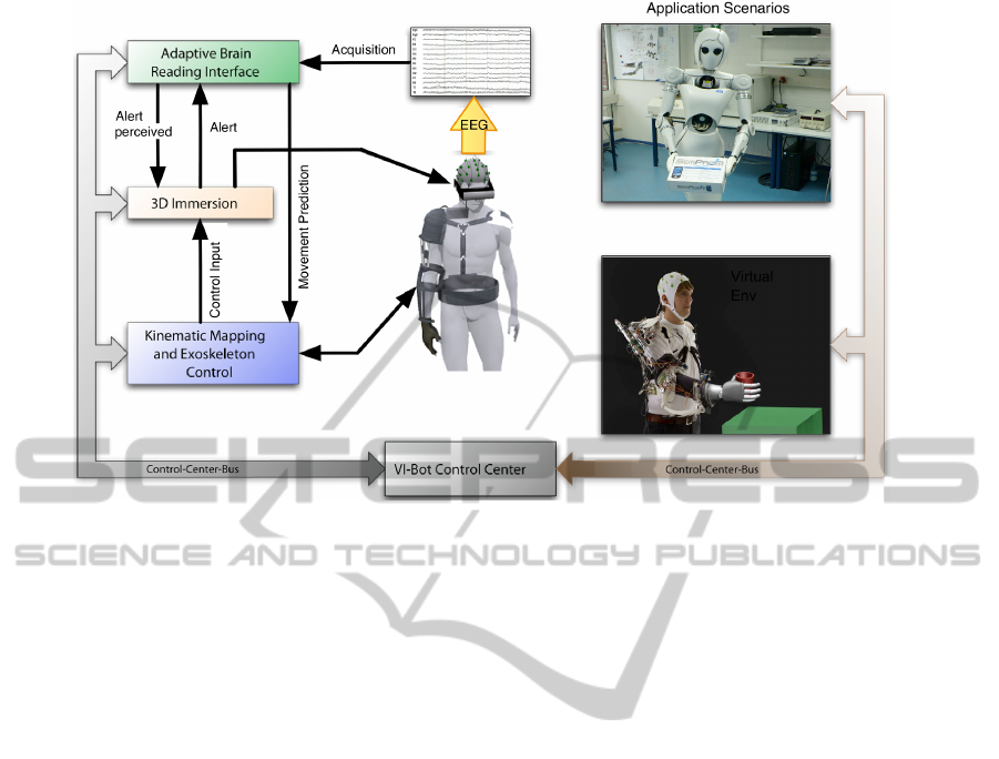
Figure 1: The Overall Control Framework Architecture.
classified with a perceptron. Furthermore they used
additionally frequency features for the detection of
ERD/ERS and improved classification performance
(Li et al., 2004). Nevertheless both approaches were
not tested in an online manner.
Beside the discrimination of right vs. left move-
ment, it is in an online scenario of particular impor-
tance to detect the movement per se. For this pur-
pose, Blankertz and colleagues outlined another clas-
sifier, which is tested in combination with the clas-
sifier performing the left-right movement discrimina-
tion. However, the authors admit, that further research
has to be done to improve the distinctness of the clas-
sifier output (Blankertz et al., 2002).
2 THE MULTI-MODAL
CONTROL ARCHITECTURE
One main goal of our project is to develop a multi-
modal control interface that will enable a single hu-
man operator to control such complex robotic sys-
tems in an intuitive way. The interplay between a
safe wearable exoskeleton, an adaptive Brain Reading
Interface (aBRI), and a multipurpose virtual environ-
ment will lift the control of different robotic systems
up to the next level, enabling to dissolve the bound-
aries between robot and operator, as well as combin-
ing the cognitive abilities of the human with the ro-
bustness of the robotic system. Figure 1 depicts the
overall control scenario where the user, at the cen-
ter of the architecture, is wearing the three interfaces.
This paper mainly focuses on the exoskeleton and the
aBRI; the 3D-Immersion and Control Center modules
are therefore not described in detail. In particular, a
control scheme is proposed that uses the information
coming from the detection of movement preparation
(Section 4) to modulate the behavior of the haptic in-
terface and therefore to improve the interaction expe-
rience between the user and the robotic system. How-
ever, for the acquisition of the electroencephalogram
(EEG), a virtualized scenario is used as explained in
Section 4.2.
Due to the fact that the kinematics of the exoskele-
ton and its control system were tailored on the base of
the anatomy and neurophysiology of the human limb
(Section 3), such interface is also suitable for deliv-
ering a precise and customized rehabilitation therapy
for the human arm.
In particular, we want to introduce an approach
for the support of patients suffering from a partial
lack of the control of their motor system. For sev-
eral reasons, e.g., after an accident, it might be hard
for a patient to move an injured limb properly with
the required force and precision. To assist recovery of
the patient, we want to apply a wearable exoskeleton
whose functionality is based on a bio-inspired con-
trol strategy that allows a natural integration of pre-
dictions regarding the prepared movements of the pa-
tient. Pre-knowledge about movements allows the
system to support the patient more accurately. The
movement prediction is based on the on-line analy-
BIODEVICES 2011 - International Conference on Biomedical Electronics and Devices
152

sis of brain activity. The integration of this informa-
tion into the control architectures allows to support
the patient even in situations where he or she can-
not move his/her limb by him-/herself, but brain ac-
tivity can still be measured. For this purpose, single
trial online-detection of movement-related brain ac-
tivity without knowing movement onset has to be ac-
complished. To achieve this, our framework for aBRI
(Kirchner et al., 2009; Kirchner et al., 2010) was ex-
tended to allow movement prediction based on the de-
tection of certain event related potentials (ERPs), i.e.,
the lateralized readiness potential (LRP) and the Be-
reitschaftspotential (BP) (Section 4), and integrated
into the brain-arm interface. For best results several
combinations of filters and their related data process-
ing times are compared.
The brain-arm haptic interface will not only support
the execution of the movement by reinforcing the
strength, but also by supporting the patient for a pre-
cise trajectory execution. Due to the fact that the joint
impedance is modulated via the integration of the
movement preparation signal and the measurement
of the exoskeleton-arm interaction forces, the system
will always respond in a natural way according to the
prepared user movement. The presence - at joint level
- of different safety mechanisms (Folgheraiter et al.,
2009c) will guarantee that the torque/force applied to
the limb will be limited within a proper range. This
is very important in order to avoid uncomfortable or
even dangerous postures for the user.
3 EXOSKELETON
INTERFACE - DESIGN
AND CONTROL
The arm interface is a 9 DOF wearable exoskele-
ton designed to deliver a fine force feedback in three
contact points with the user limb: shoulder, upper-
arm, and forearm. The device is hydraulically as
well as pneumatically actuated; the pump, compres-
sor, and primary power supply are located outside the
exoskeleton to avoid additional weight to the system.
In total there are seven actuated joints: five lo-
cated in the shoulder/upper-arm and two in the fore-
arm (Figure 2). Two additional passive joints allow
the wrist supination-pronation, finally two adjustable
links permit the adaptation of the shoulder and upper
arm lengths to the specific user anthropometry.
The haptic interface is intended to be easily worn
by the user due to the presence of adjustable strips and
belts around the upper-body, upper arm, and wrist.
During operation, all reaction forces are loaded on the
Figure 2: The 9-DOF arm exoskeleton.
back of the operator, therefore the weight of the sys-
tem is not directly perceived on the limb. Although a
big effort was dedicated to keep the structure as light
as possible, at the moment the full prototype has a
weight of 14 Kg, as thus for usage as rehabilitation
tool needs to be supported by a tutor, which can be
connected in the back part of it.
3.1 Exoskeleton Kinematics Design
To define the kinematic architecture of the exoskele-
ton, at first we modeled the human arm using a com-
mon notation from robotics, this enables us to easily
combine the two systems in order to study the over-
all mobility. Figure 3 depicts, that the coupled arm-
exoskeleton system shows different closed kinematics
loops. This in general brings restriction to the move-
ments of the limb, requesting a proper analysis of the
combined system.
Through a series of simulations, and by the in-
tegration of real arm trajectories, it was possible to
set the requirements to design the final device (Fol-
gheraiter et al., 2009b), e.g., number and configura-
tion of the DOF, angular range for each joint, opti-
mal link dimensions, joint-articulation alignment, and
maximum joint torque required. The kinematic archi-
tecture, depicted in Figure 3 (blue parts), includes a
total of 9 DOF. Starting from the back connection to-
ward the upper arm contact point (where Ja5 is lo-
cated), the presence of 5 actuated DOF guaranty free
mobility of the shoulder as well as the possibility to
deliver a three-dimensional force feedback. From the
upper-arm toward the forearm other 4 DOF allow the
elbow flexion-extension and the forearm pronation-
supination. To notice that the additional DOF that
let the wrist flexion-extension are not consider in this
study; this is due to the fact that the last contact point
between the haptic interface and the arm is located
before the wrist articulation.
A MULTIMODAL BRAIN-ARM INTERFACE FOR OPERATION OF COMPLEX ROBOTIC SYSTEMS AND UPPER
LIMB MOTOR RECOVERY
153
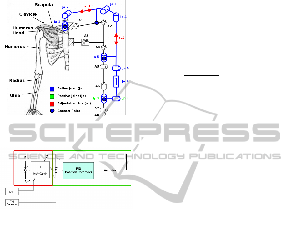
Figure 3: The simplified human arm kinematic model (right
side in gray ) combined with the exoskeleton model (in
blue).
Figure 4: Exoskeleton single joint control scheme; (left
square) force controller; (right square) cascade PID posi-
tion controller
3.2 Single Joint Control System
This section focuses on the description of the sin-
gle joint position/force controller. Both elements are
based on classical controller approaches building the
basis of the bio-inspired control scheme (Folgheraiter
et al., 2009a), (Folgheraiter et al., 2009c) as well as
the connection to the aBRI interface. Figure 4 shows
a schematic of the low-level joint controller consist-
ing of these two parts.
In Figure 4, the right square marks the cascade
PID position controller, while the left square marks
the part including the adaptive admittance controller.
Within the position controller structure, q
d
describes
the desired actuator position given by a trajectory gen-
erator located in a superior part of the overall con-
trol system, and q
act
is the actual actuator position.
Results for single joint position control are shown in
Section 5.1.
The force controller includes a variable admit-
tance filter with a specified stiffness K, damping D,
and inertia M, while q
i
is the change in actuator refer-
ence position due to an error between the desired in-
teraction force F
d
and the measured force F
meas
. The
described force controller passively regulates the in-
teraction force between the operator and the exoskele-
ton by introducing a mass-spring-damper relationship
between q
i
and F (Hogan, 1985). The transfer func-
tion of the admittance filter is given by the following
equation:
q
i
=
1
Ms
2
+ Ds + K
· (F
d
− F
meas
). (2)
The resulting deviation q
i
caused by a measured con-
tact force F
meas
has to be tracked by the subsequent
position controller described before. Through adap-
tion of the three coefficients K, D, and M using the
result of the movement preparation detection one can
specify the reaction of the device to an occurring
movement. Generally the stiffness K regulates the
amplitude of interaction force for a given trajectory,
while the damping factor D specifies whether more or
less energy is to be dissipated during the movement.
A verification of the effect of these two parameters to
admittance filter characteristic is done in 5.1. The in-
ertia factor M is neglected because the device should
not propagate a virtual mass to the operator. If move-
ment preparation is detected the values of K and D
are adjusted using Equations 3 and 4, causing the ex-
oskeleton to respond more or less sensitively to any
given force input generated by operator movements.
K = K
st
− (S
LRP
· ∆K
m
) (3)
D =
(
D
st
+ (S
LRP
· ∆D
m
) , S
LRP
< ε
D
st
−
1
1−ε
(S
LRP
− ε) · ∆D
m
, S
LRP
≥ ε
(4)
Equation 3, K
st
is representing the stiffness coeffi-
cient when no preparation of movement (LRP and
BP) is detected, S
LRP
∈ [0, 1] is the score value the
LRP detection algorithm provides to the exoskeleton
control system, and ∆K
m
is the maximum allowed
change of stiffness due to a detected movement prepa-
ration. Further, in Equation 4, D
st
is representing the
damping coefficient in case of no movement prepara-
tion (LRP and BP) detection, ∆D
m
is the maximum
allowed change of damping ratio, while ε is repre-
senting a threshold the LRP score has to overcome to
guarantee that a starting movement is quite possible.
In the overall context ε is used to tune the force con-
troller more sensitively according to the LRP detec-
tion algorithm. This means explicitly, that in case of
low LRP scores, smaller than the threshold ε, the pos-
sibility of a movement of the operator is very low. In
any case the stiffness is lowered by Equation 3 result-
ing in a higher sensitivity of the device to any given
BIODEVICES 2011 - International Conference on Biomedical Electronics and Devices
154

input. By a parallel increase of the damping the de-
vice is reacting more conveniently.
If the LRP score overcomes the threshold, stiff-
ness as well as damping are reduced, preparing the
system to react instantaneously to an expected move-
ment of the operator. Results of single joint admit-
tance control using variable stiffness and damping are
presented in Section 5.1.
4 aBRI
INTERFACE - ARCHITECTURE
AND METHODOLOGY
Most applications in the context of rehabilitation that
make use of the EEG, namely brain activity recorded
on the surface of the skull, are situated in the field
of BCIs. Those interfaces serve to restore the ability
of disabled patients to communicate (Wolpaw et al.,
2002) by enabling them to control machines or com-
puter programs by brain activity.
Our approach is not to use brain activity to di-
rectly control any devices, but to read the brain ac-
tivity to gain insight into the human mental and/or
cognitive state (Kirchner et al., 2009; Kirchner et al.,
2010). The developed interface is called adaptive
Brain Reading Interface (aBRI) and can be used to
”inform” a control scenario about, e.g., warning pro-
cessing of the user or, like in this application, the
preparation to move a certain limb. In both cases, the
aBRI will work in the background and does not re-
quire any cognitive resources of the user. The aBRI,
utilized for movement prediction, is combined and
linked via a bio-inspired control architecture with a
wearable exoskeleton which together form the brain-
arm haptic interface.
Before a movement is executed, it is planned by
the brain. Especially directed movements, in compar-
ison to, e.g., reflexes, are planned and controlled by
the cortex. Several areas of the cortex are involved
in motor planning. By detecting the activity of those
brain areas it is possible to predict the occurrence of
movement as well as which part of the body will be
moved. As presented later on, movement onset pre-
diction is done in real-time by single trial detection of
ERPs called LRP and the earlier evoked BP (Kornhu-
ber and Deecke, 1965; Balconi, 2009).
In comparison to the detection of changes in the
frequency range of the EEG (Leeb et al., 2006), the
detection of ERPs is possibly faster, since ERPs are
temporally clearly differentiated brief events and es-
pecially in the case of the BP much earlier to de-
tect. The BP, also called readiness potential (RP),
can be detected even seconds before the start of the
movement though a differentiation between the side
of movement e.g., right or left, and the part of the
body, e.g. arm or leg, can only be predicted by the
later evoked LRP which is the lateralized part of the
RP. The LRP can be measured above certain parts of
somatotopically organized brain areas to differentiate
between periods of movement and rest of correspon-
dent body areas.
Our approach therefore allows in principle not
only to detect movement onset very early by detect-
ing the BP but also to differentiate between the side of
movement and certain parts of the body by detecting
the LRP. We also believe that the detection of ERP
components is less prone to artifacts possibly origi-
nating from muscle activity or noise induced by the
exoskeleton, e.g., by hydraulic pumps or electroni-
cally controlled switches. Especially muscle artifacts
are a major problem since the subject is not seated in
a chair but is standing and therefore constantly mov-
ing slightly while wearing and using the exoskele-
ton. Since the chosen data processing for ERP detec-
tion needs only information in the very low frequency
range (below 4 Hz), rigorous filtering can be applied
that eliminates or at least strongly reduces the before
mentioned artifacts.
The challenge of our approach is the detection
of a rather weak signal of short duration at an un-
known time point. Both, BP and LRP are about 10 to
100 times smaller in amplitude than the superimposed
brain activity and can normally only be detected in av-
erage analysis (enhancing time-triggered ERP activity
and reducing so-called activity-unrelated noise). For
our approach, single trial EEG analysis in real time is
needed that has to be fast to allow multiple testing for
the occurrence of ERPs before the movement.
4.1 Framework
In this section, we present the architecture of our
framework for the aBRI that is used to make a predic-
tion whether an operator prepares to perform a move-
ment or whether he does not. This prediction is inte-
grated into the bio-inspired control architectures that
controls the stiffness of the exoskeleton.
The framework is designed to classify single trial
EEG epochs, which is a major requirement for vari-
ous different application scenarios for adaptive Brain
Reading (aBR) (Kirchner et al., 2009). Since a
machine-learning based approach is used for single
trial classification, the framework has to support vari-
ous data preprocessing methods and training sessions
of the underlying classifier.
Major requirements for the aBRI are, among oth-
A MULTIMODAL BRAIN-ARM INTERFACE FOR OPERATION OF COMPLEX ROBOTIC SYSTEMS AND UPPER
LIMB MOTOR RECOVERY
155
ers, a high classification accuracy, modular design to
facilitate the development process by rapid prototyp-
ing, different instances of possible data processing de-
signs and evaluation of the used algorithms, as well as
high performance for online data processing.
To fulfill these requirements, the data processing
system is based on the Modular toolkit for Data Pro-
cessing (Zito et al., 2008), which in turn is based on
NumPy and SciPy (Jones et al., 2001) to perform the
computations. These frameworks consist of C++ im-
plementations of the mentioned algorithms with bind-
ings to Python. Since the actual computationally in-
tensive algorithms are realized as binary object code,
the performance impairment of a scripting language
does not account here significantly.
The framework is realized as a set of independent
modules which are called nodes. Several nodes can
be assembled to create flows, where the data is trans-
ferred from one node to the next one. Different es-
pecially time-critical nodes are realized in C++ and a
channel-wise parallelization by using OpenMP.
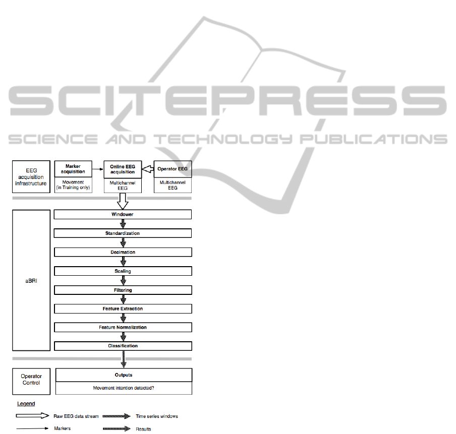
The overall processing system is structured as fol-
lows (Figure 5 for an overview):
Figure 5: Data processing scheme.
EEG Acquisition. This module acquires the data
from the EEG hardware and transfers it to the succes-
sive data processing modules. In this step, the data is a
continous stream of the raw signal data. An important
point is the capability to automatically add markers to
the datastream to label special events for training ses-
sions, e.g. when the operator starts to move or enters
a specific position. A streaming of files which contain
previously acquired EEG data is also possible.
Windowing. In this step, the raw EEG data stream
is segmented into windows of the same shape (length
of the signal frame) to extract instances which can be
processed and classified independently of each other.
This simplifies the successive computations since it
allows to work always on instances of the same shape.
The process of extracting the time windows is
called windowing. The framework is capable of us-
ing different methods for window generation, e.g. to
generate training samples for classifier training and
testing by using specified markers, or for online data
processing in the real application scenario.
In the case of BP and LRP detection later on EEG
data is segmented into windows of length of 1000 ms.
Instances containing movement preparation were cut
out with respect to a movement marker and instances
containing no movement preparation were extracted
during a rest period (Section 4.2).
Preprocessing and Feature Generation. Prepro-
cessing refers to operations aimed at increasing the
signal-to-noise ratio. It can be performed in several
steps. In Figure 5, an example flow with several dif-
ferent data processing methods is shown.
Specifically in the flow which is used later on for
the movement prediction, each window is standard-
ized channel-wise (subtraction of the corresponding
mean and division by the standard deviation). A dec-
imation is applied afterwards with an anti-aliasing
filter to reduce the sampling rate of the data from
5000 Hz to 20 Hz.
After that, the data is scaled with the function
specified by Equation 1 from Section 1. The next
processing step is another band pass filter with a nar-
row frequency band, which is applied to remove un-
wanted frequencies while retaining the sample rate. In
the end, the last 4 values per channel of each window
are used as the extracted features for the classifier. In
the current scenario, all features are normalized be-
fore they are used for classification.
Classification. Any kind of classification algorithm
suited for binary decision tasks can be used here. We
applied support vector machines with a linear kernel.
4.2 Experimental Setup
In this section the experimental setup which is used
for the acquisition of both training and test data is pre-
sented.
BIODEVICES 2011 - International Conference on Biomedical Electronics and Devices
156
C4 / C3
0
3
6
-3
-1000
-400 0-600 -200 200 400
movement marker
-6
-800 600 800
!V
ipsilateral (C4; n = 253)
contrallateral (C3; n = 253)
ms
a
b
Ball
presented
Rest
Position
left
Recording
Runs
Presentation
of Target Ball
Run 1
Start End
Rest
Run 3
Movement
Ball
entered
Start End Start End
ITI
Ball
presented
Rest
Window 2
Movement
Rest
Position
left
Ball
entered
Window 1
Trial 1 Trial 2
Run 2
Break
Break
...
c
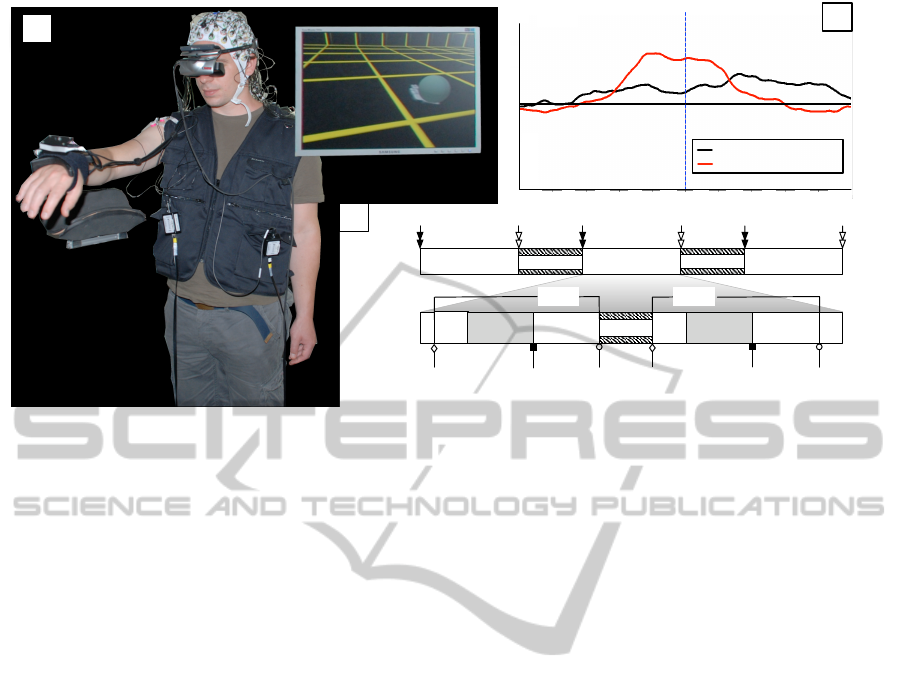
Figure 6: Experimental setup: a) Subject performs goal-oriented movements triggered by target balls; c) experimental design;
b) averaged EEG activity before and after the movement measured above the primary motor cortex areas, ipsilateral (electrode
position C4) and contralateral (electrode position C3) to the side of movement.
Subjects. Two subjects (two males, 30 and 27 years
old) participated in this experiment. The participants
were right-handed and had normal or corrected-to-
normal vision. For each participant, three runs con-
sisting of 60 trials were conducted on the same day,
two of which were used for parameter optimization
and one for validation.
Design and Procedure. Participants wore a head-
mounted display (HMD) and stood in a dimly lit room
while performing a task in a virtual environment. The
task was to move their right arm from a rest position
in order to reach virtual target balls, which were pre-
sented in the HMD to allow free movements indepen-
dent of head position (Figure 6 a).
Leaving the rest position was detected by a hand-
tracking system. Whenever the subjects moved their
arm 5 cm away from the rest position, a marker for
movement was sent and stored together with the EEG
(Figure 6 b). Based on the movement marker, the
EEG stream was segmented into windows of length
of 1000 ms (Section 4.1).
After entering the target ball, the subjects returned
to the rest position. At the same time the next target
ball appeared. Time needed to return to the rest po-
sition and for the next target ball to appear depended
on the distance between the entered target ball and
the rest position. Therefore, this time, i.e. inter-trials-
interval (ITI, Figure 6 c), varied according to the dif-
ferent distances between target balls and rest position.
To support the rest state of the arm, an armrest
that was designed as part of our test bed was used.
This arm rest was integrated into the setup to imitate
a strong support of the arm by the exoskeleton. This
is for example useful whenever a subject is holding
something still in his hand or is manipulating a de-
vice with outstretched arms. In both cases, a strong
force would rest on the arm which the exoskeleton
would support. Participants had to stay in the rest po-
sition for at least 5 seconds. In case that a subject
would leave the rest position earlier, the next target
ball would disappear. This was done to avoid too fast
changes between movement and rest which was very
important to assure long enough non-movement peri-
ods for training.
Data Acquisition. The EEG was continuously
recorded from 128 electrodes (extended 10-20 sys-
tem, actiCap, Brain Products GmbH, Munich, Ger-
many), referenced to FCz. EEG signals were ampli-
fied using four 32-channel BrainAmp DC amplifiers
(Brain Products GmbH, Munich, Germany) and fil-
tered with a low cutoff of 0.1 Hz and high cutoff of
1000 Hz. Signals were digitized with a sampling rate
of 5000 Hz. Impedance was kept below 5 kΩ.
5 RESULTS
In this section first results about performances in an-
ticipating movements via the aBRI interface, and the
suitability of the proposed control approach to modu-
late the exoskeleton joints impedance, are presented.
It is worth to mention that tests of the two interfaces,
A MULTIMODAL BRAIN-ARM INTERFACE FOR OPERATION OF COMPLEX ROBOTIC SYSTEMS AND UPPER
LIMB MOTOR RECOVERY
157
in this case, were conducted separately. Nevertheless
this is sufficient to demonstrate the feasibility of our
approach and gives solid basis to define future com-
bined experiments.
5.1 Active Exoskeleton - Results
This section provides results for position and admit-
tance control of hydraulic actuators using the schemes
described in Section 3.2. Therefore, a single joint
testbed was equipped with a hydraulic actuator driv-
ing a lever with a force sensor implemented at the
tip. Actuator positions are acquired with an absolute
optical encoder series HEDS 9040 from Agilent pro-
viding a resolution of 2880 ticks per revolution, i.e.
∆q =
0.125
◦
tick
.
Position Control Results. For evaluating the posi-
tion control performance of the testbed, a sequence
of different desired positions is given within the
workspace of −84
◦
≤ q
d
≤ 53
◦
. For a better tran-
sient behavior, changes in reference are propagated to
the control system by a PT
2
trajectory generator. See
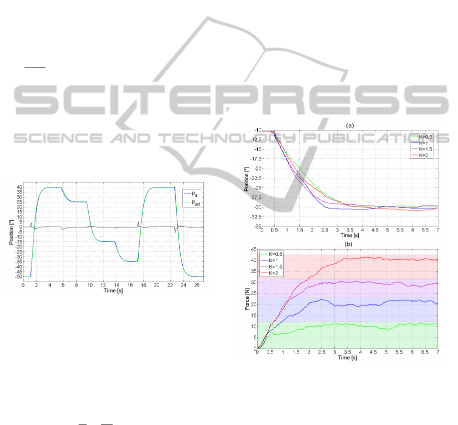
Figure 7 for results.
Figure 7: Single joint position results; solid: reference tra-
jectory; dashed: actual joint position; grey: controller error.
The control loop shows a good performance in the
overall working range. Desired positions are tracked
with a steady state error of e
ss
= 0.25
◦
which is equal
to two encoder ticks, while transients are followed by
only a small phase shift. The precision of the control
loop is limited to a minimum of one encoder tick.
The maximum angular speed of the hydraulic actuator
can be extracted to
dq
dt
=
90
◦
s
.
The position controller offers a good positioning
accuracy as well as a proper transient behavior and
thus is a suitable basis for the tracking of a given tra-
jectory.
Admittance Control Results. Here, the reaction of
the admittance control system to a given input from
an operator is demonstrated. Furthermore, the influ-
ence of the stiffness and damping parameters K and D
from Equation 2 on the behavior of the control loop
is illustrated. For the first set of experiments only an
adaption of K is performed, while damping is kept at
a constant value. Afterwards, the damping is varied
for a fixed stiffness. During all test runs, a human
is trying to move the single joint along an identical
trajectory from a start position of q
d
= −10
◦
(hori-
zontal orientation of the lever) to an end position of
q
d
= −30
◦
by exerting a force to the sensor located at
the tip of the device.
Figure 8 depicts the results of piloting the joint
in admittance control mode at different stiffness val-
ues and a constant damping of D = 0.35. Figure 8(a)
shows the movement of the actuated joint, while Fig-
ure 8(b) presents the simultaneously measured con-
tact forces. Note that the position trajectories are not
aligned because they are performed manually by a hu-
man, trying to repeat the same movement in each run.
(a)
(b)
Figure 8: a) trajectories of hydraulic joint for different stiff-
ness coefficients of admittance filter and constant damping
of D=0.35; b) measured contact force between human and
hydraulic actuator during the movements
It is obvious that an increase of the stiffness coef-
ficient in the range of K ∈ [0.5, 2] results in a higher
contact force between operator and device during the
whole movement, i.e. more force has to be generated
by the user to transfer the system to the wanted posi-
tion. Moreover, it can be determined that the steady
state value for the contact force is directly propor-
tional to K. Utilizing these results in the overall sce-
BIODEVICES 2011 - International Conference on Biomedical Electronics and Devices
158

nario, the idea of lowering the stiffness according to
a measured LRP will result in a smaller impedance of
the device against performed motions, reduce the im-
pact force at the beginning of the movement, and thus
makes the device more transparent to the user.
In the next step, the influence of the damping co-
efficient D to the control loop is investigated, keeping
the stiffness at a constant value of K = 1. Results of
this experiment are depicted in Figure 9, while Figure
9(a) again shows the movement of the device, Figure
9(b) is containing the related force curves.
(a)
(b)
Figure 9: a) trajectories of hydraulic joint for different
damping coefficients of admittance filter and constant stiff-
ness of K=1; b) measured contact force between human and
hydraulic actuator during the movements
By changing the damping ratio only the transient
behavior is influenced, while the steady state values
end up in the same interaction force governed by the
stiffness coefficient. Mechanically damping can be
described as a sink which dissipates more energy
the higher it is. Experimental results verify this
point of view by showing that the user has to apply
more force for higher than for lower ratios, to get the
device from the start to the end point in the same time.
5.2 aBRI - Movement Prediction
Results
Three different analyses are presented below to out-
line our approach and to show current work. The
aim of aBRI is to distinguish between the two classes:
“no movement” and “movement”. In contrast to var-
ious BCI-groups dealing with ERP research (Section
1), which often use accuracy as a performance mea-
sure of their systems, here Area Under Roc is ap-
plied. There are two reasons: first, the datasets are
unbalanced (about four times more “no movement”
instances) and second, even this class ratio might not
be constant, e.g., in the online case. So a performance
measure beeing robust against a varying class ratio
has been chosen (Fawcett, 2006).
Data Processing Optimization Results. For the
capability of the system to detect and respond to
a movement preparation before its actual execution,
both the classification performance and the running
time of the data processing are important factors.
To get an impression which algorithms are appli-
cable for online detection, the running time and the
classification performance of several algorithms were
measured and compared. A major bottleneck of the
data processing are all operations that are applied be-
fore the decimation (which is the reduction of the
sample rate with preceding filtering) since these have
to deal with a high amount of data. In the used flow
(Figure 5), these are the standardization and the anti-
alias filtering step of the decimation itself.
To evaluate which algorithm is suitable for the
filtering step decimation procedure, different anti-
aliasing filters (AAF) were compared. All filtering
steps of the AAF were applied in two consecutive
steps (with decimation factors of 25 and 10, respec-
tively). The inspected types were: the use of no filter
at all (called downsampling in the following), a finite
impulse response filter (FIR, applied as a direct form
time domain convolution with a filter kernel having a
length of 31 taps designed using the window design
method and using a hamming window, omitting the
time series values that are irrelevant due to the subse-
quent downsampling), and an elliptic infinite impulse
response filter (IIR, with 60dB stopband attenuation
with an order of 10, realized in direct form). Of the
successive operations, the application of the band pass
filter (BPF) was another time-consuming step, so that
different types of BPF were examined (again with the
described FIR and IIR filters, and simply using an
FFT to set all unwanted frequencies to 0). For the
evaluation of the classification performance, several
high and low cutoffs of the BPF and several complex-
ities (SVM parameter) were tested additionally.
Repeated measures ANOVA with four factors was
performed: AAF (IIR, FIR, Downsampling), BPF
(FFT, FIR, IIR), Low/High cutoff (0.4/4.0, 0.1/4.0,
0.4/2.0, 0.1/2.0) and SVM complexity (5.0, 1.0, 0.1,
0.01). Subsequently, repeated measures ANOVA with
two factors was performed: AAF (IIR, FIR, Down-
A MULTIMODAL BRAIN-ARM INTERFACE FOR OPERATION OF COMPLEX ROBOTIC SYSTEMS AND UPPER
LIMB MOTOR RECOVERY
159
sampling) and BPF (FFT, FIR, IIR, No). If needed,
Greenhouse-Geisser correction was applied and the
corrected p-value is reported. For pairwise compar-
isons, Bonferroni correction was applied.
A main effect of AAF [F(2, 94) = 8.07, p <
0.005; pairwise comparisons: IIR > Downsampling,
IIR > FIR, Downsampling vs. FIR: n.s.] and a main
effect of BPF [F(2, 94) = 14.99, p < 0.001; pairwise
comparisons: FFT > FIR, IIR > FIR, FFT vs. IIR:
n.s.] were found. There was an interaction between
two factors [BPF x AAF: F(4, 188) = 79.05, p <
0.001]. Pairwise comparisons showed that the best
combination was ”IIR AAF-FFT BPF-0.1/4.0 Hz-0.1
complexity”. Subsequent analysis of control condi-
tion (No BPF with three types of AAF) revealed that
the best combination was significantly better than the
control condition [p < 0.002].
Beside the classification performance, the com-
puting time was evaluated. Even if the corresponding
computations are performed on a high performance
computing system in parallel, the used algorithms
play an important role.
The running times are the averages of the wall-
clock processing times of windows of all datasets that
were used in the optimization procedure. We used an
Apple Mac Pro with two Intel Quad-Core Xeon pro-
cessors (resulting in 16 virtual cores due to Hyper-
Threading) at 2.66 G Hz and 32 GB memory for the
time measurements. A channel-wise parallelization
of the used filtering procedures and the standardiza-
tion was performed using OpenMP. The average and
maximum running times are shown in Table 1.
Table 1: Average (and maximum computation times in
brackets) of different filtering algorithms in ms.
Anti alias
filter type
Band pass filter type
FIR IIR FFT No
FIR 26.4
(64.3)
25.4
(30.6)
28.0
(34.5)
20.3
(24.5)
IIR 25.4
(28.4)
24.9
(28.0)
27.6
(31.6)
20.2
(27.1)
No 20.7
(25.0)
19.8
(26.6)
22.4
(29.9)
14.7
(21.5)
Time-Dependent Classification Performance.
Apparently, the longer the distance in time between
classification and actual movement onset, the more
difficult it is for the algorithm to detect the BP/LRP.
In addition neurobiological analysis about the be-
ginning of movement preparation from averaging
lots of trials for the channels C3 and C4 (Figure
6 c) does not allow to draw conclusions for the
multi-channel single trial case. To obtain knowledge
about how performance increases with sliding in
time closer to the movement, a 5×2 cross-validation
with the optimized parameters on one dataset of each
subject was performed. These datasets were not
used for the optimization procedure to ensure reliable
performance measurements.
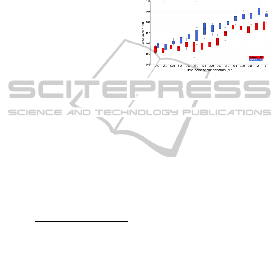
Figure 10: Boxplots of the time-dependent classification
performance for two subjects: NP (red) & CJ (blue).
Figure 10 shows the evolvement of performance
over time, whereas the time points denote the end of
each extracted time window. I.e., one box plot de-
picts the result for a classifier trained on windows
up to a specific time point and tested on other trials
windowed with the same procedure. Note that the
movement marker (time point zero) does not indicate
movement onset, since it is stored when the subject
had already moved 5 cm. That means, the interest-
ing range for the brain-arm interface would be quite
before that point (at least around -150 to -250 ms).
Although, in the online case, there is no time-
dependent classification possible and also the subject-
specific differences need further investigations, these
results demonstrate that the approach in principle al-
lows to detect movement preparation.
Online Simulation Results. Since, in the real ap-
plicable system, there will be a continuous movement
prediction, another test was conducted on the same
datasets as for the time-dependent test, but this time
in an pseudo online manner. For the test, a classifier
with optimized parameters was trained on two differ-
ent windows of each trial, i.e., cut out up to -250 and
-150 ms. This was done to make the classifier some-
how robust (Blankertz et al., 2006) against the “mov-
ing” LRP in the windows. The classifier is then tested
on sliding windows extracted every 50 ms.
For the “Force Control” module of the brain-arm
interface, a continuous value S
LRP
from 0 to 1 is ex-
pected. To achieve this, the SVM score can be used
and scaled in the demanded range. In Figure 11, the
classifier output against the time point of classifica-
tion is shown. It is below zero if an instance is classi-
fied to be “no movement” and above zero otherwise.
BIODEVICES 2011 - International Conference on Biomedical Electronics and Devices
160
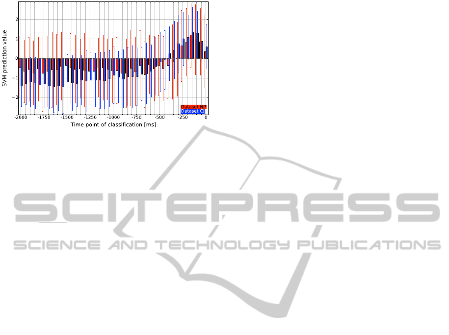
Figure 11: Mean (bars) with standard deviation (errorbars)
of the SVM prediction values for sliding windows of the
test datasets of two subjects: NP (red) & CJ (blue).
Scaling can be done for example by
S
LRP
=
svm
min
if svm
a
< svm
min
svm
a
2·svm
max
+ 0.5 if svm
a
∈ [svm
min
, svm
max
]
svm
max
if svm
a
> svm
max
where svm
a
is the SVM score for the actual classi-
fied time window in the online test case and svm
min
& svm
max
are the minimum and maximum values for
the SVM score obtained in the training phase of the
classifier.
6 CONCLUSIONS AND FUTURE
WORK
This paper proposes the architecture of a multimodal
haptic interface that has two main fields of appli-
cation: as a control device to operate complex and
heterogeneous robotic systems in an intuitive man-
ner, and as rehabilitation tool in order to facilitate
and speedup the recovery procedure of upper limbs.
In particular a control scheme that combines bio-
inspired with classical control techniques, and in-
tegrates information about movements preparation,
is presented. In comparison to classical BCI ap-
proaches, the proposed aBRI interface does not use
brain signal, to directly control the movements of the
haptic device, on the contrary the information is used
to modulate its impedance and therefore to facilitates
the prepared user movements. This improves the nat-
ural feeling in wearing the interface, enhancing the
operation of the robotics system, and increasing the
quality of the therapy.
Results show that modulating the stiffness and
damping of the force controller can be used on one
hand to ensure a safe interaction in case of low LRP
detection scores, by avoiding a too sensitive reaction
to motion inputs from the operator. On the other hand,
this feature can be used to facilitate the ability of the
system to work as a rehabilitation device, resisting or
supporting the movements of a user.
For future work we plan to improve performance
of the movement prediction by e.g., investigating sev-
eral other classification and data processing algo-
rithms, perform a thorough evaluation of filter al-
gorithms and further smoothing methods, as well as
combining the detection of ERPs and changes in the
frequency range. Further on, we will improve adapt-
ability to different users and changes in brain activity
during the usage by the development of self-adapting
methods for aBRI.
Finally experiments that combine both interfaces
(Exoskeleton, aBRI) have to be conducted, this in or-
der to demonstrate the feasibility of the proposed con-
trol approach in a real time scenario. Questions rel-
atively the user comfort and the benefits of the on-
line joint stiffness modulation have to be addressed
via testing the system on different users.
REFERENCES
Balconi, E. (2009). The multicomponential nature of
movement-related cortical potentials: functional gen-
erators and psychological factors. Neuropsychological
Trends, 5:59–84.
Blankertz, B., Curio, G., and M
¨
uller, K. (2002). Classifying
single trial EEG: Towards brain computer interfacing.
In Advances in neural information processing systems
14: proceedings of the 2001 conference, pages 157–
164. MIT Press.
Blankertz, B., Dornhege, G., Lemm, S., Krauledat, M., Cu-
rio, G., and M
¨
uller, K. (2006). The Berlin Brain-
Computer Interface: Machine learning based detec-
tion of user specific brain states. Journal of Universal
Computer Science, 12(6):581–607.
Blankertz, B., Dornhege, G., Sch
¨
afer, C., Krepki, R.,
Kohlmorgen, J., M
¨
uller, K., Kunzmann, V., Losch,
F., and Curio, G. (2003). Boosting bit rates and er-
ror detection for the classification of fast-paced motor
commands based on single-trial EEG analysis. IEEE
Transactions on Neural Systems and Rehabilitation
Engineering, 11(2):127.
Farwell, L. and Donchin, E. (1988). Talking off the top of
your head: toward a mental prosthesis utilizing event-
related brain potentials. Electroencephalography and
clinical Neurophysiology, 70(6):510–23.
Fawcett, T. (2006). An introduction to ROC analysis. Pat-
tern recognition letters, 27(8):861–874.
Folgheraiter, M., Bongardt, B., Albiez, J., and Kirchner, F.
(2009a). Design of a bio-inspired wearable exoskele-
ton for applications in robotics. In International Joint
Conference on Biomedical Engineering Systems and
Technologies (BIOSTEC-2009), Portugal, Porto.
A MULTIMODAL BRAIN-ARM INTERFACE FOR OPERATION OF COMPLEX ROBOTIC SYSTEMS AND UPPER
LIMB MOTOR RECOVERY
161

Folgheraiter, M., Bongardt, B., de Gea Fernand
´
ez, S. S. J.,
Albiez, J., and Kirchner, F. (2009b). Design of
an arm exoskeleton using an hybrid motion-capture
and model-based technique. In IEEE International
Conference on Robotics and Automation(ICRA-2009),
May 12-17, Kobe, Japan.
Folgheraiter, M., de Gea, J., Bongardt, B., Albiez, J., and
Kirchner, F. (2009c). Bio-inspired control of an arm
exoskeleton joint with active-compliant actuation sys-
tem. Applied Bionics and Biomechanics, 6(2):193–
204.
Harwin, W., Patton, J., and Edgerton, V. (2006). Challenges
and opportunities for robot-mediated neurorehabilita-
tion. Proceedings of the IEEE, 94(9):1717–1726.
Hogan, N. (1985). Impedance control - an approach to ma-
nipulation. i - theory. ii - implementation. iii - appli-
cations. ASME Transactions Journal of Dynamic Sys-
tems and Measurement Control B, 107:1–24.
Jones, E., Oliphant, T., Peterson, P., et al. (2001). SciPy:
Open source scientific tools for Python.
Kirchner, E. A., Metzen, J. H., Duchrow, T., Kim, S.,
and Kirchner, F. (2009). Assisting telemanipulation
operators via real-time Brain Reading. In Lemgoer
Schriftenreihe zur industriellen Informationstechnik,
Paderborn.
Kirchner, E. A., W
¨
ohrle, H., Bergatt, C., S. K. Kim, J.
H. M., and Kirchner, F. (2010). Towards opera-
tor monitoring via brain reading - an eeg-based ap-
proach for space applications. In Procedings of the
10th International Symposium on Artificial Intelli-
gence, Robotics and Automation in Space.
Kornhuber, H. and Deecke, L. (1965). Hirnpoten-
tial
¨
anderungen bei Willk
¨
urbewegungen und passiven
Bewegungen des Menschen: Bereitschaftspotential
und reafferente Potentiale. Pl
¨
ugers Archiv f
¨
ur die
gesamte Physiologie des Menschen und der Tiere,
284:1–17.
Krauledat, M., Dornhege, G., Blankertz, B., Curio, G., and
M
¨
uller, K. (2004). The Berlin brain-computer in-
terface for rapid response. Biomedizinische Technik,
49(1):61–62.
Krebs, H. I., Ferraro, M., Buerger, S. P., Newbery, M. J.,
Makiyama, A., Sandmann, M., Lynch, D., Volpe,
B. T., and Hogan, N. (2004). Rehabilitation robotics:
pilot trial of a spatial extension for mit-manus. Jour-
nal of Neuroengineering and Rehabiltation, 1(1):5.
Leeb, R., Keinrath, C., Friedman, D., Guger, C., Scherer,
R., Neuper, C., Garau, M., Antley, A., Steed, A., and
Slater, M. (2006). Walking by thinking: the brain-
waves are crucial, not the muscles! Presence: Teleop-
erators and Virtual Environments, 15(5):500–514.
Li, Y., Gao, X., Liu, H., and Gao, S. (2004). Classifica-
tion of single-trial electroencephalogram during finger
movement. IEEE Transactions on biomedical engi-
neering, 51(6):1019–1025.
Masaki, H., Wild-Wall, N., Sangals, J., and Sommer, W.
(2004). The functional locus of the lateralized readi-
ness potential. Psychophysiology, 41(2):220–230.
Mistry, Mohajerian, and Schaal (2005). Arm movement ex-
periments with joint space force fields unsing an ex-
oskeleton robot. In 9th International Conference on
Rehabilitation Robotics.
Pires, G., Nunes, U., and Castelo-Branco, M. (2007).
Single-trial EEG classification of movement related
potential. In IEEE 10th International Conference on
Rehabilitation Robotics, 2007. ICORR 2007, pages
569–574.
Reinkensmeyer, D., Lum, P., and Winters, J. (2001). Emerg-
ing technologies for improving access to movement
therapy following neurologic injury. Emerging and
Accessible Telecommunications.
Reinkensmeyer, D. J., Emken, J. L., and Cramer, S. C.
(2004). Robotics, motor learning, and neurologic re-
covery. Annual review of biomedical engineering,
6:497–525.
Rosen, J., Perry, J., Manning, N., Burns, S., and Hannaford,
B. (2005). The human arm kinematics and dynam-
ics during daily activities - toward a 7 dof upper limb
powered exoskeleton. In Advanced Robotics, 2005.
ICAR ’05. Proceedings., 12th International Confer-
ence on, pages 532–539.
Sajda, P., Gerson, A., Muller, K., Blankertz, B., and Parra,
L. (2003). A data analysis competition to evaluate ma-
chine learning algorithms for use in brain-computer
interfaces. IEEE Transactions on neural systems and
rehabilitation engineering, 11(2):184–185.
Schiele, A. and van der Helm, F. (2006). Kinematic design
to improve ergonomics in human machine interaction.
IEEE Transactions on neural systems and rehabilita-
tion engineering, 14(4):456–469.
Squires, N., Squires, K., and Hillyard, S. (1975). Two va-
rieties of long-latency positive waves evoked by un-
predictable auditory stimuli. Electroencephalography
and clinical Neurophysiology, 38(4):387–401.
Wolpaw, J., Birbaumer, N., McFarland, D., Pfurtscheller,
G., and Vaughan, T. (2002). Brain-computer inter-
faces for communication and control. Clinical neuro-
physiology, 113(6):767–791.
Zito, T., Wilbert, N., Wiskott, L., and Berkes, P. (2008).
Modular toolkit for data processing (mdp): a python
data processing frame work. Front. Neuroinform.,
8(2).
BIODEVICES 2011 - International Conference on Biomedical Electronics and Devices
162
