
MEASURING INTENTION TREMOR IN MULTIPLE SCLEROSIS
USING INERTIAL MEASUREMENT UNIT (IMU) DEVICES
Laurence P. Ketteringham, Simon A. Neild, Richard A. Hyde
University of Bristol, Dept. Mechanical Engineering, Queen’s Building, University Walk, Bristol, BS8 1TR, U.K.
Rosemary J. S. Jones, Angela M. Davies Smith
Bristol & Avon Multiple Sclerosis (BrAMS) Centre, Frenchay Hospital, Bristol, BS16 1LE, U.K.
Keywords: Measurement, Tremor, Multiple sclerosis, MS, Inertial measurement unit, IMU.
Abstract: This paper describes research to create a sensor based measurement system in order to provide detailed and
accurate data on the movement disorder known as intention tremor, a condition that affects a significant
proportion of individuals with multiple sclerosis. Intention tremor is a complex movement disorder that
worsens during goal directed movements and can therefore be extremely disabling. Multiple inertial
measurement unit devices were used to measure the upper limb of subjects with multiple sclerosis and
intention tremor during standard clinical finger-to-nose tests and reach-retrieve tasks, which were designed
to mimic activities of daily living. Analyses allowed information on tremor characteristics to be ascertained
during these movements. The equipment and software provide a useful tool for clinical assessment of
tremor, displaying a variety of relevant information at differing levels of detail, obtainable at several points
over the torso, shoulder, upper arm, lower arm and hand. Examples of this data are discussed. The system
allows tremor assessment in more detail than is possible with clinical tests that rely on visual assessments,
and provides a tool that can accurately assess the benefits of future tremor reduction devices, or other
interventions.
1 INTRODUCTION
MS is the most common disabling neurological
condition affecting young adults (Calabresi, 2004).
The onset of symptoms is typically between 20 and
45 years of age. More than 2.5 million individuals
worldwide have MS. MS leads to substantial
disability in more that 50% of patients (Prat, et al.,
2002).
Though currently incurable, several treatments
are available which may slow the appearance of new
symptoms and reduce the severity of existing ones.
Movement disorders, including tremor, often
occur as a result of MS. Tremor is estimated to
affect 75% of people diagnosed with MS; it can be
severely disabling and extremely difficult to treat
(Alusi, et al., 1999). A form of tremor called
intention tremor (sometimes described as, or as a
sub-category of, kinetic tremor) is especially
common in MS. This tremor exhibits itself during
purposeful movement, such as reaching out or
picking up an object, rather than at rest. It is often
accompanied by slower, uncoordinated movements
and a tendency to overshoot or undershoot targets,
referred to as ataxia and dysmetria, respectively
(Alusi, et al., 1999). Muscle weakness and sensory
impairments are also found (Alusi, et al., 2000);
these are likely to further complicate the movement
disorder. Wrist, elbow and shoulder tremors were
found to be particularly disabling when they
occurred during activities of daily living (ADL)
(Alusi, et al., 2001).
Initial work in this area discussed the use of
miniature accelerometer and gyroscope micro-
electromechanical systems (MEMS) sensors for
measuring positions and movement (Hyde, et al.,
2008). Such sensors have been combined into
devices that provide three orthogonal axes each of
accelerometer, gyroscope and magnetometer
measurements, together with microprocessors that
convert these readings into 3D orientations in space.
The early development of these sensors is detailed in
Luinge, et al., 2004 Luinge, et al., 2005. These have
since been developed into commercial devices and
204
P. Ketteringham L., Neild S., Hyde R., S. Jones R. and Davies Smith A..
MEASURING INTENTION TREMOR IN MULTIPLE SCLEROSIS USING INERTIAL MEASUREMENT UNIT (IMU) DEVICES.
DOI: 10.5220/0003156002040211
In Proceedings of the International Conference on Biomedical Electronics and Devices (BIODEVICES-2011), pages 204-211
ISBN: 978-989-8425-37-9
Copyright
c
2011 SCITEPRESS (Science and Technology Publications, Lda.)

several publications discuss their use in human
measurement, monitoring and rehabilitation
applications (e.g., Heinz, et al., 2006, Beauregard,
2007, Moore, et al., 2007 and Zhou, et al., 2006).
2 MOVEMENT MEASUREMENT
Several commercial systems that can provide 3D
orientations in this manner are discussed in
Ketteringham, 2010. The sensors used in this work
were chosen for their ability to provide 3D
orientation measurements in real-time, in an easily
applied, unobtrusive system. These data can be used
to give the position and movement of body segments
in space.
This research used a set of 5 MTx sensors (in an
Xbus kit, Xsens Technologies, The Netherlands).
The computed 3D orientation from each of the 5
sensors was recorded over time during each run. The
MTx sensors communicated with a battery powered
Xbus Master unit that was worn on the body and
communicated wirelessly with a PC.
The five sensors were positioned over the body
surfaces at the torso, shoulder, upper arm, lower arm
and hand, allowing the orientation of each body
segment to be found at each point in time. The base
of the torso was assumed to be static. Applying the
measured body segment orientations to the known
body segment dimensions allowed calculation of the
body segment displacements, along with the
displacements of points in space that move in
relation to the body segments (e.g. a held object).
The relative orientations between segments (joint
rotations) can also be found, and these can each be
converted into a set of three rotations (Euler angles)
that represent the rotation of each the joint around
three orthogonal axes. These angles could prove
useful in clinical practice if there was a requirement
to study a specific joint angle, or set of joint angles.
The displacement and angle data can also be
differentiated with respect to time to produce
velocities and accelerations, and angular rates and
angular accelerations. Further analyses can reveal
the frequency content of the movements. The joint
angles, angular rates and angular accelerations have
also been used in inverse dynamics models, created
in the Matlab
®
SimMechanics™ toolbox, for
estimating joint torques during the movements, as
described in Ketteringham, 2010 and Ketteringham,
et al., 2008.
The movement measurement system therefore
provides a useful tool for measuring tremor levels
and movement capabilities in individuals during
clinical assessments. It allows quantitative
assessment of the efficacy of other treatments in a
less subjective manner and in far more detail than is
possible with visual assessment alone.
3 EQUIPMENT AND
EXPERIMENTAL DESIGN
The Xbus Master was wirelessly interfaced via
Bluetooth
®
to a portable PC running code written in
Matlab, to obtain orientation and sensor data from
the MTx sensors. Data were obtained at 50 Hz for
each of the 5 MTx sensors.
3.1 Initial and Clinical Measurements
Ethical approval was obtained before carrying out
these studies, and all subjects completed consent
forms at or prior to the time of testing.
The subjects were initially tested to determine
their symptom characteristics, before attachment of
sensors. The initial clinical tests consisted of:
A check for pain-free range of joint movement;
An evaluation of eyesight;
Muscle strength evaluation assessed on a
Motricity scale;
A Fahn test for upper limb tremor and ataxia.
These joint range of movement, eyesight and
muscle strength tests were carried out to ensure that
the subjects could comfortably carry out the tasks
required during the recorded movements. Further
details are given in Ketteringham, 2010.
The Fahn test consisted of a tremor assessment
by observation while the subject held a pose, to
assess postural tremor, and performed a finger-to-
nose test, to assess kinetic and intention tremor. The
subject was asked to hold a pose and perform these
actions while a clinician observed the resulting
movements.
Resting tremor was assessed with the subject
sitting upright and fully supported by a high-backed
chair, with arms fully supported against gravity on
the chair’s armrests. Postural tremor was assessed
while the subject sat upright, with their arms held
out in front of them (elevated to 90° flexion) so that
the upper arm, lower arm and hand were horizontal,
and pointed directly forwards, with the hands
shoulder width apart and palms faced downwards.
Kinetic and intention tremor were assessed during a
finger-to-nose test, described below. The movement
towards the nose in the finger-to-nose test was used
to assess kinetic tremor, while the part of the finger-
MEASURING INTENTION TREMOR IN MULTIPLE SCLEROSIS USING INERTIAL MEASUREMENT UNIT (IMU)
DEVICES
205

to-nose test where the finger approached and briefly
remained at the nose was used to assess intention
(goal oriented) tremor. Feys et al., 2003 discuss the
reliability of the observed finger-to-nose test for
rating tremor.
Body segment dimensions were measured before
attachment of the sensors, as described in
Ketteringham, 2010.
3.2 Sensor Positioning
The MTx sensors were placed as follows, locating as
flat an attachment position under each sensor as
possible:
1. On the midline of on the torso, over the upper
part of the body of the sternum, pointing
superiorly (upwards);
2. On the superior aspect (top) of the shoulder, on
a flat region (where one could be found),
medial to the acromion process, pointing
laterally (to the side, along the shoulder);
3. On the distal end of the upper arm (the end of
that segment that is closest to the hand),
proximal to the lateral epicondyle, pointing
distally (towards the hand end of the arm);
4. On the distal end of the lower arm, proximal to
the wrist, on the dorsal surface (at the position
that a watch would normally be worn),
pointing distally;
5. On the dorsal surface (back) of the hand,
pointing medially (inwards, towards a plane
that divides the left and right sides of the
body).
These sensor locations were chosen, in
consultation with medical professionals, as being
positions on the body where minimal skin movement
artefacts would occur, due to movement of the
flexible and compressible soft tissues that cover the
more rigid skeletal structures beneath.
Sensor positions can be seen in Fig. 1 (with the
exception of the sensor on top of the shoulder).
Sensors on the top of the shoulder, arm and hand
were all positioned so that they were as horizontal as
possible when the arm was in the starting position
(described below).
The MTx sensors were adhered to the skin
surface using PALstickies™ hydrogel adhesive pads
(PAL Technologies Ltd, UK) in order to prevent the
sensors moving relative to the skin surfaces.
MaxWrap™ silicone elastic straps (La Pointique
Int’l Ltd., USA) were wrapped around the upper
arm, lower arm and hand over the sensors to ensure
minimal movement between the sensors and the
underlying rigid body structures. The straps are not
shown in Fig. 1, for clarity of the sensor positioning.
Figure 1: MTx sensor positions on the torso, shoulder (at
the top of the image, under clothing), upper arm, lower
arm and hand.
The Xbus Master data transmitter, which the
sensors were attached to, is shown as the white box
at the bottom of Fig. 1, attached to the subject with
the supplied waistband.
3.3 Sensor Calibration and Starting
Position
At the beginning of each movement test, which
consisted of three replicates of each type of
movement, the torso, shoulder, arm and hand were
stabilised in the starting position (described below)
for six seconds to allow the sensor readings to
stabilise and to obtain the initial sensor orientations.
The physiotherapist stabilised the arm in the starting
position by grasping the hand and the elbow, and
maintained as steady and stable a position as was
possible. The pose was held as steadily as possible
during this time, despite some subjects finding it
difficult to maintain a completely relaxed, steady
pose, even when fully supported and stabilised by
the physiotherapist.
The starting pose was defined as:
The torso held as upright as possible facing
forwards;
The shoulder and upper arm longitudinal axes
pointed laterally (to the side);
The lower arm and hand longitudinal axes
pointed to the front;
The fingers pointed forwards, with the hand
held flat, palm faced downwards.
All body segments were held as horizontal as
possible (except the torso, which was held vertical),
with orientations as close to the world X-, Y- and Z-
axes as possible, as shown in Fig. 2. It was the
central axis of each segment (considered to be the
BIODEVICES 2011 - International Conference on Biomedical Electronics and Devices
206

line that directly linked the joints between the body
segments) that was held aligned to the world X-, Y-
and Z-axes when in this starting pose.
This starting pose was easy for the
physiotherapist to maintain and had the additional
advantage of starting each axis of rotation, of each
joint, at a position that was close to the centre of its
range of movement. This meant that the joint angles
would be much less likely to vary by as much as
±90° from this position during these movement tests,
which is a great advantage when working with Euler
angles, as discontinuities can be achieved if the
middle angle of a set of Euler angles reaches ±90°.
Figure 2: Representation of the body segments for the left
arm (thick, purple lines), in the starting position, viewed
from behind and to the left. Sensors are shown as orange
wireframe boxes, in their average orientations during this
period, and in the approximate positions relative to each
body segment. World axes are shown as red, green and
blue arrows (X-, Y- and Z-axes, respectively) at the base
of the torso. Local axes of each sensor are shown in the
same colours, emanating from the centre of each sensor’s
base. The thin green line connects the point of interest
(green dot, described below) with the hand.
Average sensor orientations were obtained
during the sixth second of measurement. Since the
orientation of each body segment was known during
this time, the orientation offset between each sensor
and the body segment that it was attached to could
be found. Each of these orientation offsets was
removed from the orientations measured at each
sensor over the entire data recording period,
providing the orientations of the body segments
themselves.
Once the orientations of the body segments were
calculated, the displacements of the body segments
in space, relative to the origin at the base of the
torso, were found by multiplying the rotation
matrices representing the body segment orientations
with vectors representing the dimensions of the body
segments, then attaching the rotated body segment
vectors end-to-end, to provide a model of the body
segments like that in Fig. 2.
3.4 Movements Measured using
Sensors
Both clinical finger-to-nose and reach-retrieve tests
were measured using the sensors. The reach-retrieve
tests were designed to measure movement and
tremor during task-oriented (“functional”) everyday-
type movements. The movements were
unconstrained to make them as representative as
possible of movements in ADL.
The clinically assessed, and sensor-measured,
finger-to-nose tests used in these tests were similar
to those tested in Feys, et al., 2003 (which compared
a variety of methods). The movement sequence is
described below:
1. Starting at a holding position, with the arm
outstretched, and all limb segments pointing
laterally (to the side), with the elbow fully
extended, all arm segments held as horizontally
as possible;
2. Flexing the elbow to move the finger to the
nose;
3. Arriving at the nose and holding the finger at
the nose (or as close to it as possible) for a
short time;
4. Extending the elbow, and returning the arm to
the outstretched position.
The physiotherapist stood in front of the subject
and demonstrated the required movement before the
tests began. The clinical finger-to-nose test was
observed from in front of the subject.
The reach-retrieve movement required the
subject to move a ball between a near and a far cup,
in the sequence described below:
1. Starting at a resting position moving the hand
forwards to pick up the ball, initially situated
at the far cup;
2. Carrying the ball from the far cup to the near
cup and depositing it;
3. Moving back to the rest position after
depositing the ball, and resting briefly at the
rest position;
4. Moving forwards, from the rest position to pick
up the ball, now situated at the near cup;
5. Carrying the ball from the near cup to the far
cup and depositing it;
6. Moving back to the rest position after
depositing the ball.
The subject rested their arm before, between and
after each reach-retrieve part in a position where it
MEASURING INTENTION TREMOR IN MULTIPLE SCLEROSIS USING INERTIAL MEASUREMENT UNIT (IMU)
DEVICES
207

was completely supported by the armrest of the chair
in which they were seated. This allowed their tremor
to subside between movements, which gave visual
pointers to the duration of the movements in the
resulting data and provided a relatively static period
in which the sensors could reset the drift that can
occur in the readings during higher frequency
movements.
The balls in the reach-retrieve tests were moved
forwards and backwards between shallow cups,
which stabilised their position when being picked up
and deposited and provided a clear goal of where the
ball should be deposited, fixing the positions that the
ball was moved between. The far cup was positioned
at a distance in front of the subject that provided a
comfortable full reach, while the near cup was
positioned 5 cm from the edge of the table. Both
cups were positioned directly in front of each
subject’s shoulder joint. The distance between cups
depended on the subject’s stature, and varied from
14 to 20 cm.
3.5 Selecting a Point of Interest
A “point of interest” (POI) was chosen in order to
simplify study of the measured movements. This
was considered to be the part of the body, or a
position relative to a body part, that the subject was
concentrating on during the tests. For this reason, the
POI was considered to be in a different position
depending on the test being carried out. The POI
was considered to be the tip of the middle finger if a
finger-to-nose test was being carried out, or below
the palm of the hand (as shown in Fig. 2.), at the
position that the centre of the ball would be when
the ball was being carried in the hand. This POI
rotated with the rotation of the hand, and so it was
always in the same position relative to the hand.
Some example data, showing the displacement
of the POI in space, are discussed below.
3.6 Data Analysis and Filtering
In order to study the tremor in the movements, the
displacements of the POI in space were filtered to
leave only the high frequency components. A high-
pass fifth order Butterworth filter with a cutoff
frequency of 2 Hz was applied to the data in
forwards and reverse directions, to provide acausal
filtering. This filter gave a sharp separation between
the high and low frequencies, with minimal ripple in
the passband, and 50% attenuation of the data at
frequencies of 2 Hz (as it was applied to the data
twice).
The X-, Y- and Z-axis displacement data were
filtered separately, to leave only the high frequency
components that were superimposed on top of the
lower frequency voluntary (intentional) and ataxic
movements.
While the alignment of the tremor with the X-,
Y- and Z-axes can indicate, to some degree, which
joints are involved in the tremor movements, it may
be better, from a clinical point of view, to simplify
the data by combining the tremor displacements in
the three X-, Y- and Z-axes into a single measure of
tremor displacement, in an arbitrary direction. These
data represent the magnitude of the tremor at any
point in time, and can be calculated as a “3D
hypotenuse” of individual displacements in the X-,
Y- and Z-axes:
2
,
2
,
2
,, ZtYtXtmt
dddd ++=
(1)
where d
t,m
is the tremor displacement magnitude
in an arbitrary direction, and d
t,X
, d
t,Y
and d
t,Z
are the
tremor displacement magnitudes in the individual
X-, Y- and Z-axes. This reduces the data set
threefold, while maintaining information on the
magnitude of tremor, in an arbitrary direction.
Obtaining the tremor magnitude in an arbitrary
direction requires squaring the data, however,
leading to loss of sign information. This can give
inaccurate results when analysing the resulting
rectified data for frequency information (as an
example, a rectified and non-rectified sine wave
contain different frequency components). A method
was created to negate portions of the resulting data,
in order to return it to being a waveform that
represented the tremor movements alternating to
“either side” of the lower frequency data, as
discussed in Ketteringham, 2010.
Windowed power spectra were calculated at
regular intervals through the resulting tremor
magnitude data. The power spectra were calculated
at time increments of 0.3 s, with a time window size
of 1.3 s. This window size was found to be optimal
in terms of producing good frequency and time
resolution; a shorter window was more responsive to
rapid changes in movement while a longer time
window gave better differentiation of the
frequencies contained in the data. The power
spectrum obtained from each analysed window of
data was normalised to the maximum power in that
time window, as this provided a clearer indication of
the dominant frequencies throughout the data. The
power spectrum analysis was limited to a maximum
of 8 Hz.
BIODEVICES 2011 - International Conference on Biomedical Electronics and Devices
208
4 RESULTS: EXAMPLE DATA
FROM FINGER-TO-NOSE AND
REACH-RETRIEVE TESTS
The following results are example data from a
subject completing the first of three replicates of a
finger-to-nose test and a reach-retrieve test, in Fig. 3
and Fig. 4, respectively. The data represent the
movements of the POI in space, analysed as
described above, shown as a contour plot of the
normalised, windowed power spectra, together with
a concurrent plot of the displacement data.
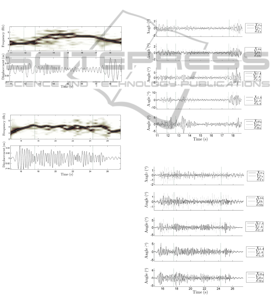
Figure 3: Tremor frequencies and displacements of the
POI during a finger-to-nose test.
Figure 4: Tremor frequencies and displacements of the
POI during parts 1 to 3 of a reach-retrieve test.
The dotted line that passes through the power
spectra from left to right indicates the frequency
with the maximum power in each of the time
windows. The vertical dash-dot lines in Fig. 3
(nominally) separate the four regions of the finger-
to-nose test, as described above. Fig. 4 shows only
parts 1 to 3 (of parts 1 to 6, described above) of a
reach-retrieve test, as the data in parts 4 to 6 were
fairly similar to the first three parts, and the duration
of parts 1 to 3 was similar to that of one replicate of
the finger-to-nose test, giving a better comparison.
Again, the parts are separated by vertical dash-dot
lines.
The lightness of the regions on the contour plot
shows the relative power of the particular
frequencies at a particular time, where a darker
region indicates the dominant frequencies (those
with a higher power). No power magnitude (colour
bar) is shown with the contour plot, as the maximum
power values in each time window were normalised,
so the maximum “elevations” are of value 1.
High frequency Euler angle data (three
orthogonal rotations for each joint in the body
model) are also shown, in Fig. 5 and Fig. 6. The high
frequency angle data were obtained from the Euler
angle data by applying the same high-pass, acausal,
fifth order Butterworth filter, with a cutoff frequency
of 2 Hz, as described above.
Figure 5: High frequency components of the joint angles
during a finger-to-nose test.
Figure 6: High frequency components of the joint angles
during a reach-retrieve test.
MEASURING INTENTION TREMOR IN MULTIPLE SCLEROSIS USING INERTIAL MEASUREMENT UNIT (IMU)
DEVICES
209

The subscripts Ts, Sh, UA, LA and Ha in the
legends indicate the particular joint that the torso,
shoulder, upper arm, lower arm and hand segments
are rotating about. X, Y and Z indicate the axis that
the rotation is about. These rotations were aligned
with the world X-, Y- or Z-axis, respectively, when
the body was held in the starting position. This is
discussed in more detail in Ketteringham, 2010.
5 DISCUSSION OF RESULTS
The tremor frequencies found in the data were
mainly between 3 and 5 Hz. This agrees with
descriptions given in several previous studies (e.g.
Alusi, et al., 2001, Gillard, et al., 1999 and Deuschl,
et al., 1998). The tremors described in such
publications are often reduced to simple values,
without reference to changes over time. These data
show that the tremor frequencies are by no means
constant throughout an unrestricted, full arm
movement, but vary due to the configuration of the
arm, and may be affected by the stiffness of the
joints due to muscle co-contraction. There are also
points in the data where the tremor movements are
not at a single, dominant frequency, but are
distributed over a range of frequencies.
Many previous studies have restricted movement
to one joint axis, one joint or a small range of joints.
In these cases a more limited range of frequencies
may be witnessed. These kinds of studies can not
represent the tremor as seen in full, unrestricted
movement, though. Measurements of unrestricted
movements are arguably more useful when studying
movement in ADL, in order to ascertain
improvements in tremor due to interventions or other
methods for controlling tremor.
Some frequencies below 3 Hz can be seen during
the more restful periods at the beginning and end of
the reach-retrieve movements. These parts also had
low amplitudes in the tremor, as tremor subsided on
cessation of movement. At other times during the
reaching task, the tremor was relatively stable in
terms of frequency and amplitude, though the
amplitude varied somewhat over a period of 2-3
cycles, probably due to changes in the configuration
of the arm during the task and the interactions
between the tremors that arose in the joints. Similar
characteristics can be seen in the joint angles in Fig.
6. The tremor took 2-3 cycles to reach full amplitude
on beginning the task.
The finger-to-nose test showed quite different
characteristics. While the tremor was of a similar, or
slightly higher, frequency during the parts where the
finger was held at or near the nose, larger, lower
frequency tremor occurred at the beginning and end
of the movements.
At the beginning of each finger-to-nose
movement, the subject held their arm out to the side.
A typical stabilisation tactic for subjects with tremor
is to “lock” the lower arm and wrist joints at the end
of their range of movement while the arm is in this
position, with the elbow (Z
LA
in Fig. 5 and Fig. 6)
extended, the lower arm (Y
LA
) supinated (to turn the
palm upwards) and the wrist (X
Ha
) extended. This
was the case during this test.
Little tremor can originate at the elbow, lower
arm or wrist when in this position, but it can once
the movement to the nose has commenced and the
joints can move more freely. The arm is also longer
and more rigid in this configuration, making it act
like a longer pendulum of larger mass, compared to
when the elbow, especially, is more flexed. These
factors can lead to lower frequency, larger
magnitude tremor displacements at the hand.
Similar features can also be seen in the joint
angles in Fig. 5, and the tremor can be seen to
originate more from the torso and shoulder at the
beginning and end of the test movements, where the
distal joints are less free to move.
6 CONCLUSIONS
This kind of coupled measurement and analysis
system can be seen to provide detailed and useful
data for measuring and investigating movement and
tremor.
The system can be used to generate a wide
variety of data, including displacements of the body
segments in space and joint angles. As discussed
earlier, these data can be further analysed to produce
kinematic data sets which can be used to drive
inverse dynamic models to obtain joint torque
estimates.
On their own, however, these displacements can
still be a useful measure of the tremor present in an
individual's movements, and should prove to be a
useful tool in clinical practice, whether used for
assessment of tremor progression or for assessment
of the effects of an intervention to improve tremor.
The different movements in the two tests
measured here result in observable differences in the
resulting tremor. The characteristics of the tremor
change more during the finger-to-nose test than
during the reach-retrieve test. The configuration of
the arm when fully extended can be seen to lead to
lower frequency, larger amplitude tremors. These
BIODEVICES 2011 - International Conference on Biomedical Electronics and Devices
210

are similar to those seen in a typical clinical
“postural” tremor test, where tremor is observed
while the arms are held out, fully extended in front
of the body. The tremor can not occur to such a
degree in (especially) the elbow when in this
position. The extended arm represents a longer
pendulum of larger mass than when the elbow is
flexed, so a lower frequency movement results,
emanating from the torso and shoulder joints.
It could be argued that the positions held, and
movements made, in the finger-to-nose tests are not
particularly “functional” (i.e. representative of a
typical everyday action, or ADL), and that the
tremor seen during a task with the arm held
outstretched is somewhat an artefact of the position
that the arm is held in.
Movements such as the reach-retrieve task
described here could be said to be more
representative of ADL. The characteristics of the
tremor during those tasks were relatively consistent
throughout, and there was no opportunity for joints
to be “locked” at the limit of their range of motion.
ACKNOWLEDGEMENTS
This research was supported by the UK Engineering
and Physical Sciences Research Council (EPSRC)
under a Doctoral Training Account, EP/P501326/1,
and by the UK charity MS Research.
REFERENCES
Alusi, S. H., Glickman, S., Aziz, T. Z., Bain, P. G., 1999.
Tremor in multiple sclerosis. Journal of Neurology,
Neurosurgery, and Psychiatry, 66, pp.131-134.
Alusi, S. H., Worthington, J., Glickman, S., Findley, L. J.,
Bain, P. G., 2000. Evaluation of three different ways
of assessing tremor in multiple sclerosis. Journal of
Neurology Neurosurgery and Psychiatry, 68, pp.756-
760.
Alusi, S. H., Worthington, J., Glickman, S., Bain, P. G.,
Apr 2001. A study of tremor in multiple sclerosis.
Brain, 124(4), pp.720-30.
Beauregard, S., 2007. Omnidirectional pedestrian
navigation for first responders, in: 4th Workshop on
Positioning, Navigation and Communication 2007,
(WPNC07), Hannover, Germany.
Calabresi, P. A., 2004. Diagnosis and management of
multiple sclerosis. American Family Physician,
70(10), pp.1935-1944.
Deuschl, G., Bain, P., and Brin, M, 1998. Consensus
statement of the movement disorder society on tremor.
Movement Disorders, 13(S3), pp.2–23.
Feys, P. G., Davies-Smith, A., Jones, R., Romberg, A.,
Ruutiainen, J., Helsen, W. F., Ketelaer, P., 2003.
Intention tremor rated according to different finger-to-
nose test protocols: A survey. Archives of Physical
Medicine and Rehabilitation, 84, pp.79-82.
Gillard, D. M., Cameron, T., Prochazka, A., Gauthier, M.
J. A., 1999. Tremor suppression using functional
electrical stimulation: a comparison between digital
and analog controllers. IEEE Transactions on
Rehabilitation Engineering, 7(3), pp.385–388.
Heinz, E., Kunze, K., Gruber, M., Bannach, D., Lukowicz,
P., 2006. Using wearable sensors for real-time
recognition tasks in games of martial arts - an initial
experiment. In: 2006 IEEE Symposium on
Computational Intelligence and Games, Reno, NV.
pp. 98-102.
Hyde, R. A., Ketteringham, L. P., Neild, S. A., Jones,
R.J.S., 2008. Estimation of Upper-Limb Orientation
Based on Accelerometer and Gyroscope
Measurements, IEEE Transactions on Biomedical
Engineering, 55(2), pp.746-754.
Ketteringham, L. P., 2010. Measuring and Controlling
Upper Limb Tremor in Individuals With Multiple
Sclerosis. PhD thesis. Department of Mechanical
Engineering. University of Bristol, UK.
Ketteringham, L. P., Neild, S. A., Hyde, R. A., Jones, R. J.
S., Davies Smith, A., 2008. Intention tremor in
multiple sclerosis: measuring and modelling arm
dynamics and elbow torque. In: Proceedings of the
ASME International Mechanical Engineering
Congress & Exposition, 35, pp.19-26. Boston,
Massachusetts, USA. Paper number: IMECE2008-
66140.
Luinge, H. J., Veltink, P. H., 2004. Inclination
measurement of human movement using a 3-d
accelerometer with autocalibration. IEEE Transactions
on Neural Systems and Rehabilitation Engineering,
12, pp.112-121.
Luinge, H. J., Veltink, P. H., 2005. Measuring orientation
of human body segments using miniature gyroscopes
and accelerometers. Medical & Biological
Engineering & Computing, 43, pp.273-282.
Moore, S., H. G., M., J. M., G., H. S., C., W. G., O., 2007.
Long-term monitoring of gait in Parkinson’s disease.
Gait & Posture, 26, pp.200-207.
Prat, E., Martin, R., 2002. The immunopathogenesis of
multiple sclerosis. Journal of Rehabilitation Research
and Development, 39(2), pp.187-199.
Zhou, H., Hu, H., Tao, Y., 2006. Inertial measurements of
upper limb motion. Medical and Biological
Engineering and Computing, 44, pp.479-487.
MEASURING INTENTION TREMOR IN MULTIPLE SCLEROSIS USING INERTIAL MEASUREMENT UNIT (IMU)
DEVICES
211
