
ELECTRONIC INTERFACE AND SIGNAL CONDITIONING
CIRCUITRY FOR DATA GLOVE SYSTEMS USEFUL
AS 3D HMI TOOLS FOR DISABLED PERSONS
Giovanni Saggio, Stefano Bocchetti, Carlo Alberto Pinto and Giancarlo Orengo
Dept. of Electronic Engineering, University of Rome “Tor Vergata”, Rome, Italy
Keywords: Data glove, Human machine interface.
Abstract: A simple PC screen can be considered as an interface of a virtual environment where an user can move
objects and interact with them. The interaction tools can be simply a virtual mouse or a keyboard. But it is
evident how these tools cannot provide an immersive experience since the bi-dimensionality of the screen.
So in the latter years the virtual reality is becoming more and more accomplished by new hardware
interfaces capable to increase the realism degree. Among all, the sensorized glove is becoming one of the
more interesting and promising of these interfaces. Here we propose the electronic interface and signal
conditioning circuitry we adopt as the most suitable for our developed data glove system. The same solution
we adopted can be usefully extended for other specific systems that treat signals coming from sensors which
read kinematics from disabled persons with reduced Range Of Motion (ROM) capabilities.
1 INTRODUCTION
Nowadays people with disabilities have the
possibility to communicate with other persons via
computers, but most of the peripherals (keyboard,
mouse, tablet, ..) cannot be user-friendly for some
disabilities. So new user input methods are welcome,
especially the ones that can utilize the residual motor
capabilities of motor disabled persons. Among all
the new inputs methods, the data glove can result
one of the more interesting and promising solution
because it can take into account the specific needs of
disabled users. Equivalent mouse commands can be
provided by hand motions and real keyboard
functions can be obtained virtually pressing the keys
displayed on a computer screen, thanks to the
movements of fingers measured by the data glove.
Figure 1: Data glove commands virtual keyboards.
In addiction such a data glove can furnish new
computer interaction possibilities, since allows the
user to interact in a virtual 3D space rather than
mouse and keyboard which act in a 2D plane.
The data glove is basically a common glove but
with the characteristic of being endowed with
sensors by which it is possible to measure the flex-
extension and abdu-adduction of finger movements,
the wrist postures and the relative position of the
hand in the space. Different kinds of sensors, based
on different principles, can be adopted to this aim,
such as accelerometers, gyroscopes, Hall effect
based devices, piezoresistors and so on (Dipietro L.
et al., 2008). Using the same kinds of sensors it is
possible to measure the Range Of Motion (ROM) of
practically any junction of the human body (wrist,
knee, neck, elbow, ..) In any case the measured
electric signals, coming from the sensors, must be
then conditioned, recorded and sent to a receiver for
further exploitation, so a wireless transmitter must
be designed too. Finally the overall system has to
provide real-time measurements of all electric
signals coming from the sensing devices.
For the electronic interface and the signal
conditioning circuitry it is desirable to perform the
following features: a) measurement range of the
electric values should be sufficiently large, b) the
248
Saggio G., Bocchetti S., Pinto C. and Orengo G..
ELECTRONIC INTERFACE AND SIGNAL CONDITIONING CIRCUITRY FOR DATA GLOVE SYSTEMS USEFUL AS 3D HMI TOOLS FOR DISABLED
PERSONS .
DOI: 10.5220/0003157402480253
In Proceedings of the International Conference on Health Informatics (HEALTHINF-2011), pages 248-253
ISBN: 978-989-8425-34-8
Copyright
c
2011 SCITEPRESS (Science and Technology Publications, Lda.)
circuit should be robust, because of the noise which
must be taken into account in wearable applications;
c) structure needs to be simplified for small size; d)
removable battery must be integrated; e) power
consumption should be low, to get a longer service
time (a continuous monitoring would be obtained
without battery replacement or recharge) and f)
comfort to wearers during common daily activities.
This is why we report here a solution we adopt as
convenient for the previous requirements for a data
glove system.
We refer to our data glove as HITEG-Glove
since our group name (Health Involved Technical
Engineering Group).
Moreover we realized a virtual hand based video
framework to have the possibility of a real-time and
off-line analysis of all the measured values.
2 DATA GLOVE
The HITEG-Glove here presented is mostly based
on bend sensors capable of measuring bending
angles thanks to the piezoresistive effect by means
of which their resistance value depends to the angle
they are submitted.
We measured performances of several bend
sensors, manufactured by Flexpoint Sensor System
Inc. and Image S.I., different in lenght and
encapsulation materials.
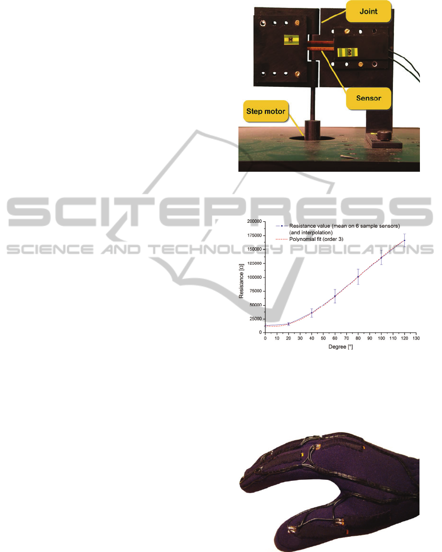
Sensors resistance variation vs. bending angle is
measured thanks to an home-made set-up based on a
hinge where the sensors lay on, and a stepper motor
which provides the rotation of one wing of the hinge
(with respect to the other which is fix constrained)
simulating a human finger joint rotation (see Fig. 2).
Each sensor can be characterized in a -90° to
180° (from inward to outward) angle range for
programmable step value of bending angle, number
of measurement repetitions and mechanical actuator
speed. At known angles, the resistance values of the
sensors are measured by an Agilent 34405A
multimeter.
Among all the performed measurements, some
relevant results are showed in Fig. 3. It reports
measurement results, resistance mean values and
standard deviations, on 6 different 2 inches length
polyimmide encapsulated Flexpoint sample sensors:
each sensor is characterized repeating measurements
10 times, varying bending angle from 0° to 120° and
return.
Figure 2: Experimental set-up for macroscopic bending
measurements: it is designed to permit testing of a single
sensor, simulating the real human finger joints kinematics.
Figure 3: Resistance variation VS bending angle: mean on
6 sample sensors and standard deviation.
After the characterization, the sensors are
mounted on a Lycra based glove, each
corresponding to a single finger joint.
Figure 4: Lycra - based HITEG Glove.
ELECTRONIC INTERFACE AND SIGNAL CONDITIONING CIRCUITRY FOR DATA GLOVE SYSTEMS USEFUL
AS 3D HMI TOOLS FOR DISABLED PERSONS
249

3 SIGNAL CONDITIONING
In this paragraph we analyze the optimized
electronic interface for our HITEG-Glove, according
to the afore-mentioned conditions listed in the
introduction. A novel approach for analog signal
conditioning before A/D conversion, which matches
the requirements is presented. System configuration,
accuracy and resolution have been analyzed in-depth
and designing rules have been defined. Experimental
results show that this electronic interface exhibits
less than 1% error in a large measurement range for
strain sensor rotation angle. It also shows a good
stability to power supply interference. The interface
has been successfully applied to a glove-based
measurement system of hand gesture.
Resistive bend sensors are integrated in clothing
to acquire wearer’s posture and movements in the
form of voltage signals. They are interestingly light,
soft and environmentally stable.
Piezoresistive sensors have been extensively
investigated with some promising ones being
explored for real applications (Saggio G. et al., 2009
- Orengo G. et al, 2009). They have a large
measurement range for outward bendings from 0° to
120°, and correspondingly the resistance normally
changes from 10 to 170 kΩ. The hysteresis they
manifest is really negligible and repeatability is
exceptional. Thanks to their high sensibility these
sensors can be adopted as a key-element for
measuring ROM of people with reduced hand
capabilities. A second key-element is our proposed
electronic interface and signal conditioning circuitry.
The optimized electronic interface for wearable
sensors here concerned is based on a differential
instrumentation amplifier. Fig. 5 shows the proposed
electronic interface.
Figure 5: Signal conditioning electronic interface
proposed.
It consists of a group of voltage dividers for
resistive sensors (one for each sensor) to extract a
voltage signal from sensor resistance variation using
a first stage input buffer. Subsequently a second
stage provides to properly shift/amplify the sensor
signals with the possibility of finely adjusting both
gain and offset level to make the levels of output
voltage dividers fit the input range of a PIC
microcontroller 12 bits A/D converter. In this way
we can measure very little signal variation
corresponding to very little joint bendings on
disabled subject. Then the microcontroller can send
the digital signals in a serial format to a general
purpose PC for post elaboration, reconverting them
to the corresponding bending angles of the joints.
Voltage dividers are used because of their simple
structures and potential high dynamic measurement
ranges they can furnish. In order to minimize the
size of the electronic interface, a single conditioning
circuit of the signal, which can be used by every
sensor implementing a polling routine on a
multiplexer, has been reasonably designed. It is
important to notice that the voltage signal variation
range can change from sensor to sensor; this is
because the technological process of factory doesn’t
produce identical devices (as it results clear by
observing the standard deviation reported on the 7
calibration points of the characteristic curve reported
in Fig. 3). Another reason is that the maximum
bending angle of each sensor depends on the joint it
is applied to; for example the sensors of the
proximal interphalangeal joints, which perform the
maximum bending angle possible (typically 120° but
in a wholly able subject), react with the largest
resistance variation.
Figure 6: Human finger joints.
For such reasons it is necessary to choose in the
design of the instrumented differential amplifier a
voltage gain (and a level shift) so to realize the best
HEALTHINF 2011 - International Conference on Health Informatics
250

match in order to make the signals of all the sensors
fit the input range of a PIC microcontroller A/D
converter. Considering a single voltage divider
(represented in the box left below in Fig. 5), a
meaningful issue in the design is how to set R
ref
. The
single element has the following voltage divider:
=
+
(1)
So, after a 120° bending:
∆
=
_
+
_
−
_
+
_
(2)
where R
sens_min
corresponds to 0° bending, whereas
R
sens_max
to 120° bending, which is the maximum
allowable flexion of a finger joint and
Δ
V
i
to the
consistent voltage variation.
In order to maximize the signal sweep for the
maximum allowed flexure degrees even for people
with a reduced ROM (which can be even much less
than 120°), the voltage divider resistance R
ref
can be
yield nullifying the corresponding partial derivative:
∆
=
_
(
+
_
)
−
_
(
+
_
)
=0
(3)
to obtain:
_
=
_
_
(4)
which corresponds to the geometric mean of the
extreme sensor resistance values.
If the sensor bending sweep is not always the
same, an optimized reference resistor for each sensor
has to be chosen. The normalized voltage signal
variation coming from each sensor becomes:
∆
=
1
_
max
+1
−
1
_
min
+1
(5)
∆
=
1
_
_
max
+1
−
1
_
_
min
+1
(6)
∆
=
1
−1
+1
−
1
+1
=
−1
+1
(7)
where:
=
_
_
(8)
The equation 7 provides the maximum voltage
divider signal variation with the optimized value for
−
. Furthermore it can be seen that a strain
sensor exhibiting the largest sweep in resistance for
a given bending angle is required, because
∆
∆
→1
for q
→∞
, even if this sensitivity is smoothed from
the root.
This is the reason which led us to prefer in this
project the Flexpoint bend sensors (q
2
=14) over
those from Image (q
2
=6), as it is represented in fig.6,
where the voltage divider sweep is plotted against
the choice of the reference resistance for different q
values.
Figure 7: Normalized voltage divider output sweep vs
reference resistor value.
Further investigation is required to set the
appropriate resolution for the A/D converter inside
the microcontroller. Naming V
n
the noise coming
from the signal conditioning circuits and V
nq
the
quantization noise, where:
=
1
√
12
2
(9)
it can be seen that the resolution N can be chosen
from the following inequality:
=
2
+
2
<
(10)
2
+
11
12
2
2
2
<
2
2
2
(11)
2
<
11
12
2
2
2
(12)
10
1
10
2
10
3
10
4
10
5
10
6
0
0.1
0.2
0.3
0.4
0.5
0.6
0.7
Flexpoint
sensor
q
2
=6
q
2
=14
R
opt
Normalized voltage sweep
Δ
V
i
/ V
cc
R
ref
Image
sensor
ELECTRONIC INTERFACE AND SIGNAL CONDITIONING CIRCUITRY FOR DATA GLOVE SYSTEMS USEFUL
AS 3D HMI TOOLS FOR DISABLED PERSONS
251
<
11
12
(13)
Since the rms noise measured at the output of the
signal conditioning circuits is V
n
=2mV, the above
equation yields N<11.
On the other hand, to guarantee a one degree
resolution for finger joints bending measurements,
supposing a linear sensor resistance variation VS
bending angle, the required number of bits is given
by:
∆
120
=
120
+1
−1
≈7.1
(14)
Since the embedded A/D converter has 12 bit, the
above mentioned conclusions allow to calculate how
many LSBs must be set to zero by the PIC.
4 VIRTUAL REPRESENTATION
Once data has been correctly acquired and converted
into digital form, all values are sent to PC with a
specific protocol useful to disambiguate and
recognize the exact sensor under investigation
(among all the 15 adopted, one at time) and its
value. So the data are tidily stored in a specific
database, one record for each sensor, one field for
each recording time. In such a way data can be
useful re-called and utilized in simple numerical
format or, more effectively, utilized to replicate the
real hand movement by a virtual avatar on a PC
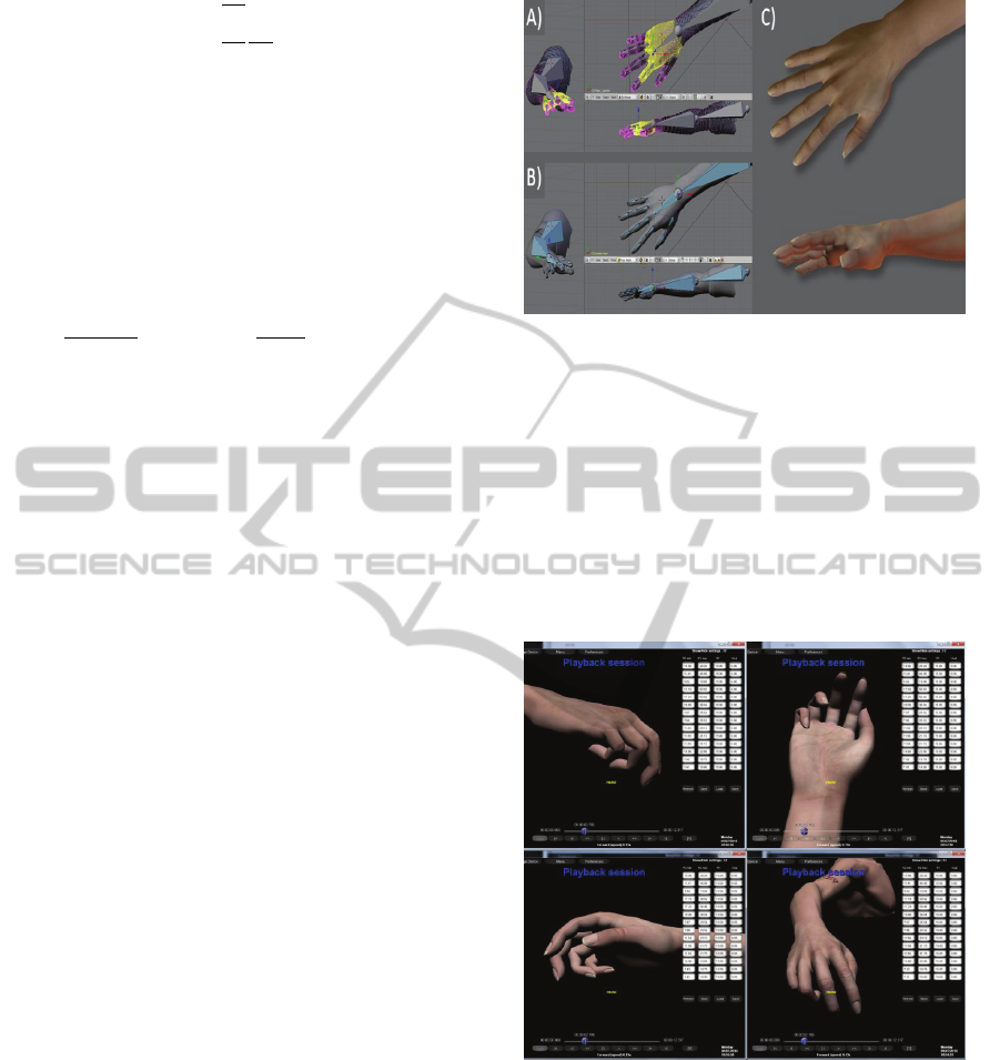
screen. With this aim, it has been realized a Graphic
User Interface (GUI), programmed in C++ language,
by means of Windows Application Program
Interfaces (API) and DirectX 9.0c. The overall
software converts digital values into bending degree
values for each finger joint and it represents all
postures on a graphical body model. A complete 3D
body model was realized starting from Blender,
which is an open source multiplatform software. In
order to animate the model mesh and make it move,
translating real human actions to virtual actions in
the simulated environment, we defined an armature
which is made of a series of invisible bones
connected to each other via parenting or constraints,
that allow us to pose and deform the geometry that
surrounds it, in this case the mesh.
The armature is used for building skeletal
systems to animate the postures of characters and
anything else which needs to be animated (see Fig.
8, A and B).
Figure 8: A 3D human hand model: A) Mesh with vertex
group (yellow selection); B) Armature: hidden hand
bones; C) Final rendering of the rigged model with
textures and lights.
The armature modifier allows objects to be
deformed by bones: as a bone moves, it deforms or
moves the vertices (single points of a mesh)
associated with it. The mesh surface is analogous to
the skin of the human body. The armature is also
called Skeleton. There are various great advantages
from the utilization of 3D virtual model of the hand.
Figure 9: A reproduction session: software allows user to
see an acquisition session off-line, and by rotating 3D
model in any direction, it is possible to analyze
reproduction from different viewpoints.
During the pre-processing data phase, the model
has been utilized as a support tool to qualitatively
verify the measurement repeatability. During the
real-time visualization phase, the model allowed the
hand visualization from different points of view, a
continuous monitoring of the coherence of data
streams and a rapid re-calibration if necessary.
HEALTHINF 2011 - International Conference on Health Informatics
252

During the post-processing data phase, thanks to
the model, it was possible to replay all the fingers
movements in slow / rapid / frame-by-frame motion
and to isolate even just one finger at a time,
removing the others from the view, in order to focus
the operator’s attention only on some important
details.
5 CONCLUSIONS
Electronic interface and signal conditioning circuitry
was developed and optimized to allow persons with
a reduced ROM to have an easier Human Computer
Interaction. In particular the interaction is obtained
by means of a data glove which demonstrated to be
one of the more interesting and promising of these
interfaces, because it can take into account the
specific needs of disabled users.
A framework of video-based virtual hand input
for using one hand, provided an easy interface of a
virtual environment where a disabled person can
move and interact simulating a virtual mouse or
keyboard. To increase the realism degree an
immersive experience was allowed by the bi-
dimensionality of the screen.
Our overall system is being tested on harm
injured patients at the Hospital structure of the ASL
Viterbo, Hand Surgery Dept., thanks to Dr. Antonio
Castagnaro and Dr. Anna De Leo.
REFERENCES
Dipietro L., Sabatini A. M. and Dario P. “A Survey of
Glove-Based Systems and their Applications” IEEE
Transactions on Systems, Man, and Cybernetics-Part
C: Applications and Reviews, Vol. 38, No. 4, July
2008.
Saggio G., Bisegna P., Latessa G., Bocchetti S.
“Mechanical modeling of bend sensors exploited to
measure human joint movements” 1
th
IEEE
International WoWMoM Workshop on
Interdisciplinary Research on E-Health Services and
Systems, IREHSS 2009, Kos (Greece) 2009, pp. 978-
1-4244-4439-7 ©2009 IEEE.
Orengo G., Giovannini L., Latessa G., Saggio G., Giannini
F., “Characterization of piezoresistive sensors for
goniometric glove in hand prostheses”, Wireless Vitae
Conference, CTIF Aalborg 2009, pp. 684-687.
ELECTRONIC INTERFACE AND SIGNAL CONDITIONING CIRCUITRY FOR DATA GLOVE SYSTEMS USEFUL
AS 3D HMI TOOLS FOR DISABLED PERSONS
253
