
A MULTI-PIN DROPLET ROUTING
ALGORITHM FOR DIGITAL MICROFLUIDIC BIOCHIPS
Pranab Roy, Hafizur Rahaman
School of VLSI Technology, Bengal Engineering and Science University, Shibpur, India
Parthasarathi Dasgupta
Indian Institute of Management Calcutta, India
Keywords: Digital Microfluidics, Algorithms, Placement and Routing, Biochips.
Abstract: Digital microfluidic biochips have emerged as a major area of attention in the fields of Clinical Research,
Medical diagnostics and are destined to revolutionize the biological laboratory procedure in coming years.
As the use of Digital microfluidic biochips becomes widespread in safety critical biomedical applications –
the need for enhanced automation for the complex biological procedures become more pronounced. In this
paper, we attempted to design a high performance routing procedure applicable for multi-pin digital
microfluidic biochips that deals with multiple source target routing in a concurrent manner using
hierarchical approach. The avoidance of cross contamination is a key challenge in the design of a biochip.
Our paper attempts to minimize this problem while parallel routing of droplets with an aim to optimize the
cell utilization and minimize the overall routing time as well. The proposed method uses a special technique
for clustering the sub-problems together and uses a hierarchical scheme to optimize the routing process.
Empirical results obtained are quite encouraging.
1 INTRODUCTION
A biochip is a collection of miniaturized test sites
(microarrays) arranged on a solid substrate that
permits many tests to be performed at the same time
in order to achieve higher throughput and speed.
The idea of low cost and reliable chip model that
resembles an electronic chip that performs thousands
of biological reactions within a very small area
gained huge interest among scientists and
biotechnologists in recent times. Because these chips
can automate highly repetitive laboratory tasks by
replacing cumbersome equipment with miniaturized,
microfluidic assay chemistries, they are able to
provide ultra-sensitive detection methodologies at
significantly lower costs per assay than traditional
methods—and in a significantly smaller amount of
space.
One of the most advanced technologies to build a
biochip is based on microfluidics where micro- or
nano-liter droplets are controlled or manipulated to
perform intended biochemical operations on a
miniature lab, commonly known as a lab-on-a-chip
(LOC).The major advantages of using microfluidics
are i) Surface effects become prominent with high
surface area to volume ratio, ii) Low thermal mass
and high heat transfer, and iii) Low value of
Reynolds number and thus laminar flows which only
result in diffusional mixing.
The earlier generation of microfluidic biochips
was based on continuous fluid flow in permanently
etched microchannels using micropumps and
microvalves for actuation. These devices relied on
electrical methods such as electrokinetics to control
the sample flows.
A major alternative is to manipulate liquid
samples as discrete droplets. The second generation
of microfluidic biochips is based on this approach
and is referred to as Digital microfluidic biochips.
Discrete droplets of the nanoliter volume are
manipulated on a patterned array of electrodes. On a
digital microfluidic biochip (DMFB), the electro-
hydrodynamic force generated by the electrodes
216
Roy P., Rahaman H. and Dasgupta P..
A MULTI-PIN DROPLET ROUTING ALGORITHM FOR DIGITAL MICROFLUIDIC BIOCHIPS.
DOI: 10.5220/0003164402160223
In Proceedings of the International Conference on Biomedical Electronics and Devices (BIODEVICES-2011), pages 216-223
ISBN: 978-989-8425-37-9
Copyright
c
2011 SCITEPRESS (Science and Technology Publications, Lda.)

controls movements of the droplets. The electrodes
in the microfluidic array are controlled by
independent control pins, which actuate free
movement of the droplets on the array. By assigning
time-varying voltage values to turn on/off the
electrodes on the digital microfluidic biochip, it is
possible to move the droplets around the entire 2D
array and perform fundamental microfluidic
operations (such as, mixing reactions) for different
bioassays. The applied voltages are changed
according to the need for moving the droplets from
one electrode to the other, and the process can be
controlled by a processor of predefined clock
frequency that determines the velocity of movement
of the droplets (Su and Chakraborty, 2004). These
operations performed under the control of the
electrodes are reconfigurable operations because of
their flexibility in area (electrodes involved) and in
execution time. Digital microfluidic biochips allow
continuous sampling and analysis capabilities for
online and real-time chemical/biological sensing.
Digital microfluidic biochips have a vast
multitude of applications including clinical
diagnosis, environmental studies, and military
operations. Due to their digital nature, any operation
on droplets can be accomplished with a set of library
operations like VLSI standard library, controlling a
droplet by applying a sequence of preprogrammed
electric signals (actuation sequences) (Zeng, Liu,
Wue and Yue, 2007).Therefore, a hierarchical cell-
based design methodology can be applied to a
DMFB.
The first top down methodology for a DMFB
proposed by (Su and Chakraborty, 2004) mainly
consists of architecture level synthesis and
geometry-level synthesis. The geometry-level
synthesis in DMFBs broadly involves placement of
modules (source, mixer and target) and droplet
routing. During module placement, the location of
each module is determined to minimize chip area or
response time. In droplet routing, the path of each
droplet transports it without any unexpected or
accidental mixing under design requirements.
In this paper, attempts are made to route 2-pin
and multi-pin nets (which imply number of droplet
samples moving to the same target is greater than or
equal to two) in digital microfluidic biochip using a
hierarchical approach. The objectives are to optimize
(i) the number of electrodes used to route all the
droplets from source to target (via the mixer in case
of multi-pin droplets) and (ii) the overall droplet
routing time. This, in turn, optimizes the area,
routabilty and throughput.
The organization of the remaining paper is
arranged as follows. Section 2 deals with existing
works on droplet routing. Section 3 depicts the
fundamentals of droplet routing. Section 4
introduces the problem formulation with multi-pin
droplet routing. Section 5 discusses the algorithm for
clustering the sub-problems together to deal with
maximum parallel routability. Section 6 describes
the routing algorithm using hierarchical approach
.Section 7 depicts the final results for the given test
cases along with graphical representation of the
clusters showing sub-problem connectivity. Finally,
section 8 provides the conclusion with analysis of
results.
2 EXISTING WORKS
A critical step in biochip automation is droplet
routing, which provides an overall estimation of the
net performance time as well as resource utilization.
Numerous techniques are proposed for optimization
of droplet routing in biochips. A graph coloring
approach was proposed by (Akela, Griffith and
Goldberg, 2006), which is applied to each successive
cycle of direct addressing solution. In this work
direct addressing was defined as the control
mechanism of droplet movement over the electrodes
by direct addressing of the micro-controller control
unit. An acyclic graph was generated based on the
movement time of the droplets and coloring was
done based on concurrent routing of droplets. DMFB
arrays with hardware limited row-column addressing
are considered, and a polynomial-time algorithm for
coordinating droplet movement under such hardware
limitations was developed. Direct addressing method
was also used by (Xu and Chakraborty, 2007) where
the droplet routing problem is mapped into graph
clique model. Droplet routing time is optimized by
optimal partitioning of the clique model. (Lin, Yang,
Wen, Ping and Sapnetkar, 2008) explored the use of
direct addressing mode in their work of routing for
biochip, using integer linear programming (ILP) to
solve the problem. In works of (Hwang, Su and
Chakraborty, 2006) dynamic reconfigurability of the
microfluidic array is exploited during run-time. The
proposed method starts with an initial placement
technique. A series of 2-D placement configurations,
in different time spans, is obtained in the module
placement phase. Then appropriate routing paths are
determined to complete droplet routing. The authors
decompose a given problem into a series of sub-
problems, based on their initial placement and solve
them sequentially to find the ultimate solution. (Cho
A MULTI-PIN DROPLET ROUTING ALGORITHM FOR DIGITAL MICROFLUIDIC BIOCHIPS
217
and Pan, 2008) proposed a high performance droplet
routing algorithm using a grid based representation.
Their proposed algorithm initially checks which
droplets can be routed freely (without any obstacle
or blockage due to other droplets). Then the droplets
are arranged to route in parallel without considering
blockage. Routing of the remaining droplets is
considered in presence of blockage and a concession
zone was introduced to ascertain feasibility of the
routing. Finally a compaction based algorithm was
run to optimize the solution. In works of (Yang, Yuh
and Chang, 2007) a network flow based method was
proposed for droplet routing. The proposed method
was based on non-intersecting bounding box
technique. The bounding box of each net was first
obtained. Then a set of nets having non-intersecting
bounding boxes were chosen for routing. The
remaining nets were routed using min-cost max-flow
algorithm. An A* search algorithm was proposed by
(Boahringer, 2006). The states of the source-target
pairs at different times are differentiated using a
graph representation. Then optimal path from source
to target was chosen using the A* search algorithm.
(Xu and Chakraborty, 2007) presented a droplet-
routing-aware automated synthesis tool for
microfluidic biochips. Droplet routability, defined as
the ease with which droplet pathways can be
determined, is first estimated and integrated in the
synthesis flow. (Zhao and Chakraborty, 2009)
proposed a droplet-routing method that avoids cross-
contamination in the optimization of droplet flow
paths. This approach targets disjoint droplet routes
and minimizes the number of cells used for droplet
routing. (Roy, Rahaman and Dasgupta, 2010)
proposed a simple algorithm for concurrent path
allocation to multiple droplets, based on the
Soukup’s routing algorithm proposed by (Soukup,
1978) together with the use of stalling, and possible
detouring of droplets in cases of contentions.
Selection of the droplets was based on the lengths of
the respective source to target Manhattan paths. A
partition-based algorithm for pin-constraint based
design was proposed in (Xu and Chakraborty, 2006).
3 DROPLET ROUTING IN
DMFBS
The primary objective of droplet routing was to
transmit all the droplets from source to target within
a 2D grid array while fulfilling all the necessary
constraints. In this regard an efficient schedule has
to be developed that provides an optimized routing
both in terms of timing as well as electrodes
utilization.
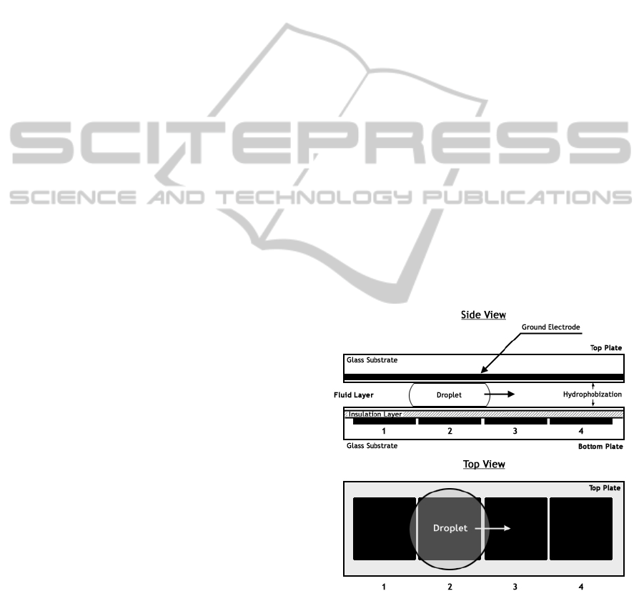
The droplets are sandwiched between two
electrodes (Fig 1) and the motion is actuated from
one electrode grid to another using the principle of
Electrowetting on dielectrics. We model the droplet
routing problem in DMFBs as a 2D-grid (Fig 2). For
each droplet, there exists a set of source grid
locations, and a set of target grid locations. Each
source to target combination is referred to as a net. If
only one source and one target are involved in a
given net, it is a 2-pin net. If multiple sources,
mixers and a single target are involved, it is a multi-
pin net. Two Sources, one Mixer and one Target
combination is referred to as a 3-pin net (Fig 3). Our
goal is to route every droplet, if feasible, from its
source location to its target location possibly through
mixers, subject to several constraints.
The constraints generally applied for droplet
routing are defined as follows. For a successful
droplet routing, a minimum spacing between
droplets must be maintained to prevent accidental
mixing. In cases of 3-pin nets or multi-pin nets,
droplet merging is desired at specific locations
termed as mixers. Several microfluidic modules
required for mixing, splitting, storage and other
operations are placed on the array. These are
considered as obstacles in droplet routing.
Figure 1: Droplet actuation principle in DMFB using
EWOD (Hwang, Su and Chakraborty, 2006).
In order to avoid conflicts between droplet routes
and assay operations, a segregation region is defined
around the functional region of microfluidic
modules. In this way, droplet routing can easily be
isolated from active microfluidic modules. During
BIODEVICES 2011 - International Conference on Biomedical Electronics and Devices
218
routing of multiple droplets concurrently in time-
multiplexed manner, there are possibilities of
intersection or overlapping of droplets coming in
collision course. Certain fluidic constraints are
introduced in order to avoid such undesirable
behavior.
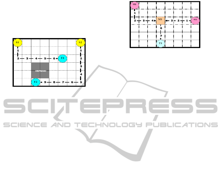
Figure 2: Droplet routing in a 2D Grid where S1, S2
represents. Sources; T1, T2 represent Targets along with
timestamps and Obstacles (Latest arrival time = 10).
Let d
id
at (x
t
i,
y
t
i
) and d
j
at (
x
t
j
, y
t
j
) denote two
independent droplets at any given timestamp t.
Then, the following constraints, generally called
Fluidic Constraint should be satisfied for any time t
during routing: (Roy, Rahaman and Dasgupta, 2010)
• Static constraint: | x
t
i
– x
t
j
| >1 or | y
t
i
– y
t
j
|
>1
• Dynamic constraint: | x
t+1
i
– x
t
j
| >1 or |
y
t+1
i
– y
t
j
| >1
Or | x
t
i
– x
t+1
j
| >1 or | y
t
i
– y
t+1
j
| >1
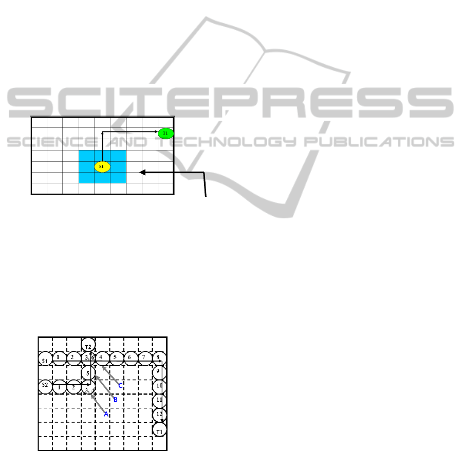
This implies that for any droplet at location
(x,y)- all the locations (x+1,y),(x-1,y),(x,y+1),(x,y-
1),(x+1,y+1),(x+1,y-1),(x-1,y-1),(x-1,y+1) are
prohibited for any other droplet to enter at
timestamp t and t + 1 in order to maintain the above
mentioned fluidic constraints. Hence, all the
locations neighboring (x,y) as referred to above
comprise the Critical Zone (Fig. 4) for any droplet at
(x,y) at time t.
The Timing Constraint provides the maximum
allowed transportation time of a droplet in the given
set.
4 PROBLEM FORMULATION
Parallel routing of droplets are necessary to optimize
the latest arrival time. In most of the approaches
described in Section 2, concurrent routing has been
attempted for those droplets whose paths are free of
obstacles. Then remaining droplets are taken care of
for their routing to respective targets sequentially
Figure 3: 3-Pin droplet routing with hierarchical approach
with two sources SX1 and SY1, One Target T1; Latest
arrival time (1
st
Generation – 5), Latest arrival Time (2
nd
Generation – 8).
using stalling and detour. In (Roy, Rahaman and
Dasgupta, 2010) however an overall concurrent
routing approach is adopted to obtain a virtual route
plan depending on relative locations of modules,
samples and targets. The results show encouraging
improvements for both time and resource
utilizations. However, no attempt has been made so
far to address the issue for multi-pin droplets as only
2-pin cases were resolved in (Roy, Rahaman and
Dasgupta, 2010) .Our work specifically attempts to
resolve the issue of 2-pin and multi-pin droplets
concurrently using a hierarchical approach for multi-
pin droplets.
The routing problem can be formulated as
follows: Given a two-dimensional array of
electrodes placed over a square microfluidic biochip
(a square layout area) as shown in Fig. 2 and Fig. 3.
A set of module locations is given in a grid. A
number of sub-problems clustered in different
subsets provide the source, target locations for 2-pin
nets and multiple source, mixer and corresponding
target locations for multi-pin nets. The objective is
to find the possible shortest path for each source to
target (via mixer, if any) taking into consideration of
the fluidic constraints mentioned in previous section
and thereby route each droplet to its destination with
optimum arrival time as well as minimal utilization
of electrodes.
In the process, we have to cluster the sub-
problems that comprise a total set into separate
subsets to maximize the number of droplets in the
individual subsets to be routed concurrently. The
reason is that it is not possible to place all the sub-
problems in a given test set at the same grid as it
violates fluidic constraints for placement. Each
cluster (subset of nets) is routed concurrently,
whereas the different clusters are routed one after
another in a sequence with clusters with largest
number of samples being routed first and so on.
A MULTI-PIN DROPLET ROUTING ALGORITHM FOR DIGITAL MICROFLUIDIC BIOCHIPS
219
5 METHOD OF CLUSTERING OF
SUB-PROBLEMS
Given a test case with n sub-problems. The fluidic
constraints for placement of source target and mixers
are as follows:
1. No two source location should coincide or
be placed at critical zone (adjacent cell) of
each other.
2. No Target location should coincide with
other or with any other mixer or in any
critical zone of mixer.
3. No Mixer should coincide with any other
mixer, source, or target or in any critical
zone of other mixer, source or target.
It is found that not all the sub-problems conform to
the placement fluidic constraints. Hence, the aim is
to cluster
Critical Zone
Figure 4: Critical zone around a droplet S1 in a moving
state (Roy, Rahaman and Dasgupta, 2010).
maximum number of sub-problems in a subset
together that do not violate the previously mentioned
constraints and route them together. Then go for the
next cluster, which contains next largest number of
sub-problems, which are not already routed in the
previous cluster. The process is continued until all
sub-problems have been considered.
Figure 5: Example of droplet routing with time stall (Roy,
Rahaman and Dasgupta, 2010).
5.1 The Clustering Algorithm
Input: A test case with n number of sub-problems,
compatibility_list[i] for each sub-problem
number i
initialized to null.
Step1: find the compatibility list for each sub-
problem
for i = 1 to n
Add i to compatibility_list[i]
for j = 1 to n
check compatibily with i (if j ≠ i)
if compatible add j to
compatibility_list[i]
end for
sort compatibility_list[i] in ascending
order of
Sub-problem Number.
end for
Step 2: Find the final set of clusters
for i = 1 to n-1
for j = i+1 to n
find intersection of compatibility_list[i]
and compatibility_list[j]
let number of elements in the
intersection set be m
for k = 1 to m
if (k ≠ i) and (k≠ j)
check compatibility of k with
other members
of the set from
compatibility_list[k]
if any member is not compatible,
exclude
them from the set comprising i, j
and k
end for
end for
end for
finally x number of sets comprising all the
numbers of
sub-problems are formed.
Step 3: Find out the set with largest number of sub-
problems.
Step 4: Exclude these members from other sets.
Step 5: Check if all sub-problems are exhausted.
Step 6: If some sub-problems are yet to be routed
repeat step 2 with remaining sets after the previously
mentioned exclusion.
Compatibility of nets may be represented as a graph,
with each node representing a net, and presence of
an edge between a pair of nets indicating their
compatibility (no violation of module placement
constraints).
BIODEVICES 2011 - International Conference on Biomedical Electronics and Devices
220

6 PROPOSED METHOD OF
ROUTING FOR EACH
CLUSTER
In this approach, we attempt an overall concurrent
routing of the droplets grouped in individual clusters
formed according the method stated in Section 5.
The method is described below:
1. The overall time is measured in terms of
timestamps for each source. For each source, the
start time is initialized to zero and a timestamp
increment of one is considered for each transition
from one cell to its adjacent cell.
2. The Manhattan distance between each source,
mixer, target combination is computed. For a 2-pin
source S
i
(x,y) and Target T
i
(x,y) the distance D
i
is
computed as [S
i
(x) ~ T
i
(x)]+ [S
i
(y) ~ T
i
(y)].For a 3-
pin source SX
i
(x,y),SY
i
(x,y) and Mixer M
i
(x,y)along
with target T
i
(x,y) -- the distance D
i
is computed as
[{SX
i
(x) ~ M
i
(x)}+ {SX
i
(y) ~ M
i
(y)}] + [{SY
i
(x) ~
M
i
(x)}+ {SY
i
(y) ~ M
i
(y)}]+ [{M
i
(x) ~ T
i
(x)}+
{M
i
(y) ~ T
i
(y)}]. Same ordering of nets is used for
multi-pin nets as well.
3. The Manhattan distance thus obtained for each
droplet set is sorted in descending order. The routing
of each droplet set (2- pin or 3-pin) is carried out in
the same order.
4. Routing of the droplets is carried out using
Soukup’s routing algorithm. For 2-pin nets each
source is routed directly towards the corresponding
target. However, for 3-pin nets each source SX and
SY is routed parallel to the corresponding mixer.
This is termed as 1
st
Generation route. The largest
arrival time T
SM
among (SX Æ M) and (SY ÆM) is
noted. Then the final mixed droplet from Mixer M is
routed to Target T. This is termed as 2
nd
Generation
route. In case of 2
nd
generation route, the timestamp
starts from T
SM
as determined earlier.
5. In case there is a clear path for any source to
target or source to mixer or mixer to target route,
then routing is completed easily. Detouring is
required in the presence of obstacles.
6. Consider the case when droplet from a source
arrives at a cell such that in the same timestamp
droplet from another source is also reaching the
same cell or in an adjacent cell within the critical
zone. In such a case, any one of the two sources is
stalled for a certain amount of time until the
difference of timestamps between the two sources
becomes at least two (Fig 5). The source with larger
Manhattan distance among the two is allowed to
route and the other one is stalled. However if it is
found that there remains a scope of detour through a
path which has been utilized before by some other
droplet – if stalling takes too long (empirically if it
is greater than 4 timestamps approximately) –
detouring through utilized path is favorable – as it
optimizes the utilization of resources in terms of
electrodes.
7. Finally, one more possibility may be encountered
while routing of droplets: deadlock. In this situation,
a droplet S
x
is stalled as it is in a collision course
with another droplet S
y
that has a higher routing
preference due to larger Manhattan distance.
However the second droplet S
y
may also get stalled
due to the movement of a Third droplet S
z
which in
turn can not move due to current position of S
x
or S
y
or any other blockage .In such cases it is necessary
to identify the specific droplet which is responsible
for deadlock – thereby detour it to a safe
position(this phenomenon is known as
retreat)through a different path and stall it to that
safe position for a certain amount of time – which
allows other two droplet to steer clear towards their
respective destinations.
In this approach we resorted to route the droplets
in an order of longest Manhattan distance first – the
reason behind this is as follows: the one expected to
take maximum time (approximately) is routed first
without any chance of stalling, thereby the critical
time, which tentatively defines the maximum arrival
time remains unaffected. This technique provided
encouraging improvement in Latest arrival time.
As already stated, during routing, attempt is
made to have a trade off between stalling and detour.
This is to optimize both time as well as total number
of unit cells utilized for routing.
7 RESULTS
The two testbenches considered are In_Vitro_1 and
In_Vitro_2. In_Vitro_1 contains twenty 2-pin
droplets and six 3-pin Droplets with eleven sub-
problems on a 16 x 16 grid. In_Vitro_2 contains
twenty-six 2-pin droplets and six 3-pin droplets with
15 sub-problems on a 14 x 14-grid electrode.
7.1 Results for In_Vitro_1
Number of Sub-problems = 11
Figure 6 represents a compatibility graph In vitro 1.
Each node of the graph represents a sub-problem,
and nodes of same color belong to the same cluster.
A MULTI-PIN DROPLET ROUTING ALGORITHM FOR DIGITAL MICROFLUIDIC BIOCHIPS
221
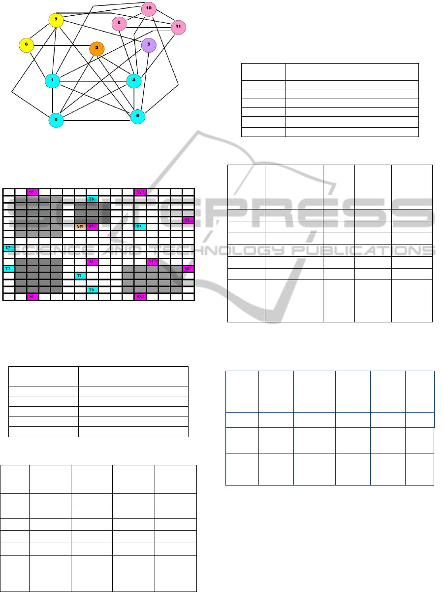
Figure 6: The sub-problem connectivity graph for
In_Vitro_1 (based on compatibility with each other) Each
color representing one cluster and each circle representing
one sub-problem.
Figure 7: Sample placement diagram for Cluster 1 for
In_vitro_1 (Source ÆPink; Target ÆBlue, Mixer
ÆOrange, Blockage ÆGray).
Table 1a: Final set of clusters obtained for In Vitro_1.
Cluster Number
Set of sub-problems in
cluster
1 {1,4,8,9}
2 {5,10,11}
3 {6,7}
4 {2}
5 {3}
Table 1b: Final Route table for all clusters for In_Vitro_1.
Grid
Cluster
No{Set}
Number of
droplets
(2pin+3pin)
Latest
Arrival
Time
Electrode
Utilization
16 X 16 1{1,4,8,9} 7+1 = 8 24 59
16 X 16 2{5,10,11} 2+2 = 4 21 51
16 X 16 3{6,7} 6+0 = 6 10 36
16 X 16 4{2} 2+1 = 3 26 47
16 X 16 5{3} 3+2 = 5 20 47
Total - 5
Total – 2-
pin – 20
3-pin – 6
Total Time
– 101
Net
Electrode
Utilization
- 131
7.2 Results for In_Vitro_2
Number of Sub-problems = 15
Table 2a: Final set of clusters obtained for In vitro_2.
Cluster
Number
Set of sub-problems in cluster
1 {1,2,7,10,14,15}
2 {5,11,12}
3 {6,9,13}
4{3}
5{4}
6{8}
Table 2b: Final Route table for all clusters for In_Vitro _2.
Grid
Cluster
No {Set}
Number
of
droplets
(2-pin +
3 - pin)
Latest
Arrival
Time
Electrode
Utilization
14 X 14 1{1,2,7,10,14,15} 7+1 = 8 16 57
14 X 14 2{5,11,12} 6+1 = 7 15 37
14 X 14 3{6,9,13} 4+2 = 6 29 49
14 X 14 4{3} 4+1 = 5 23 50
14 X 14 5{4} 3+0 = 3 12 16
14 X 14 6{8} 5+1 = 6 16 37
Total - 6
Total –
2-pin –
26
3-pin – 6
Total Time
–
111
Net
Electrode
Utilization
- 95
Table 3: A comparative result for total Electrode
Utilization With other algorithms for two test sets –
In_Vitro_1 and In_Vitro_2.
Test
Design
Prioritized
A*
Boahringer
(2006)
Two Stage
Hwang, Su,
Chakraborty
(2006)
Network
Flow
Yang, Yuh,
Chang
(2007)
Cho
Pan
Algorithm
Cho, Pan,
(2008)
Our
Algorithm
Name
Cell
Utilization
Cell
Utilization
Cell
Utilization
Cell
Utilization
Cell
Utilization
In
Vitro 1
(16 X 16)
269 263 237 258 131
In
Vitro2
(14 X14)
failed Failed 236 246 95
8 CONCLUSIONS
Here we have taken two specific test sets In_Vitro_1
(having 20 2-pin droplets and 6 3-pin Droplets with
11 sub-problems on a 16 x 16 grid) and In_Vitro_2
(having 26 2-pin droplets and 6 3-pin droplets with
15 sub-problems on a 14 x 14 grid). We attempted to
cluster the sub-problems as shown in Table 1.a and
table 2.a so as to handle as many sub-problems
BIODEVICES 2011 - International Conference on Biomedical Electronics and Devices
222

concurrently as possible taking care of the fluidic
constraints for placement (as stated in Section 5).
The results of routing giving individual latest arrival
time for each cluster as well as overall route time for
each Test set is shown in Table 1.b and Table 2.b.
The overall electrode utilization is also shown for
each test case. A comparative study with other
algorithms shows major improvement in terms of
Cell Utilization for each test case as evident from the
table 3.
Hence, in terms of resource utilization this
algorithm shows remarkable improvement and is
able to route maximum droplet as allowed by the
placement constraints concurrently. This algorithm
can be extended to more than three pins to be routed
hierarchically. Also as the routing technique used
here does not guarantee the shortest path, hence
there remains further scope of improvement
regarding this area, which may enhance the latest
arrival time further.
ACKNOWLEDGEMENTS
This work has been supported in part by VLSI
Design Project, DIT, Govt. of WB,INDIA and
SMDP-II project, DIT, MCIT, Government of
India.
REFERENCES
Huang W., Su F., Chakraborty K., 2006 “Automated
design of pin-constrained digital microfluidic arrays
for lab-on-a- chip applications”— In Proceedings of
the 43rd annual Design Automation Conference, San
Francisco, CA, USA Pages: 925 – 930.
Su F., Chakrabarty K., 2004. “Architectural-Level
synthesis of digital microfluidics-based biochips”. In
Proceedings of IEEE International Conference on
CAD, pages 223-228.
Zeng X., Liu L., Wu J., Yue R., 2007 “ Droplets Actuating
Chip Based On EWOD”. Springer-Verlag.
Akella A., Griffith E. J., Goldberg M. K., 2006
“Performance characterization of a reconfigurable
planar-array digital microfluidic system.” IEEE
Transactions Computer-Aided Design of Integrated
Circuits and Systems, 25(10):340-352, February.
Xu T., Chakrabarty K., 2007 “A cross-referencing-based
droplet manipulation method for high-throughput and
pin-constrained digital microfluidic arrays.” In
Proceedings of Design Automation and Test in
Europe, pages 552 - 557, April.
Lin, Chang Yang Chia, Wen Yeo, Ping-Hung Y.,
Sapatnekar S., 2008 “A progressive-ilp based routing
algorithm for Crossreferencing biochips.” In
Proceedings of Design Automation Conference, pages
284 - 289, June.
Hwang W., Su F., Chakrabarty K., 2006 “Droplet routing
in the synthesis of digital microfluidic biochips.” In
Proceedings of Design Automation and Test in
Europe.
Cho M. and Pan D. Z., 2008“A high-performance droplet
routing algorithm for digital microfluidic biochips.”
IEEE Transactions Computer-Aided Design of
Integrated Circuits and Systems, 27(10):406-419,
October.
Yang C. L., Yuh P. H. and Chang. Y. W., 2007 “Bioroute:
A network flow based routing algorithm for digital
microfluidic biochips.” In Proceedings of IEEE/ACM
International Conference on Computer Aided Design,
pages 752-757.
Boahringer K. F., 2006 “Modeling and controlling parallel
tasks in Droplet based microfluidic systems”. IEEE
Transactions Computer Aided Design of Integrated
Circuits and Systems, 25(2):334 - 344, February.
Xu T. and Chakrabarty K., 2007 “Integrated Droplet
Routing in the Synthesis of Microfluidic Biochips”,
Proceedings of the Design Automation Conference,
June 4-8, San Diego, California, U.S.A.
Zhao Y. and Chakrabarty K., 2009 – “Cross-
Contamination avoidance for Droplet Routing in
Digital Microfluidic Biochips”, Proceedings of the
DATE.
Roy P., Rahaman H., Dasgupta P., 2010 “A Novel Droplet
Routing Algorithm for Digital Microfluidic Biochips”,
GLSVLSI, Providence, Rhode Island, USA.
Xu T. and Chakrabarty K., 2006 “Droplet-trace-based
array Partitioning and a pin assignment algorithm for
the automated design of digital microfluidic biochips.”
Proceedings of IEEE/ACM InternationalConference
on Hardware/Software Codesign and System
Synthesis, Pages 112-117.
Soukup J., 1978 “Fast Maze Router” Proceedings of the
15
th
ACM/ IEEE Design Automation Conference, pages
100-102.
A MULTI-PIN DROPLET ROUTING ALGORITHM FOR DIGITAL MICROFLUIDIC BIOCHIPS
223
