
DEVELOPMENT OF VERTEBRAL METRICS
An Instrument to Study the Vertebral Column
António Jordão
Departamento de Física, Faculdade de Ciências e Tecnologia, Universidade Nova de Lisboa
Quinta da Torre P-2829-516, Caparica, Portugal
Instituto de Biofísica e Eng. Biomédica, Faculdade de Ciências da Universidade de Lisboa
Campo Grande, P-1749-016, Lisboa, Portugal
Pedro Duque
Departamento de Física, Faculdade de Ciências e Tecnologia, Universidade Nova de Lisboa
Quinta da Torre, P-2829-516, Caparica, Portugal
Claudia Quaresma
CEFITEC, Departamento de Física, Faculdade de Ciências e Tecnologia, Universidade Nova de Lisboa
Quinta da Torre, P-2829-516, Caparica, Portugal
Pedro Vieira
Departamento de Física, Faculdade de Ciências e Tecnologia, Universidade Nova de Lisboa
Quinta da Torre P-2829-516, Caparica, Portugal
Instituto de Biofísica e Eng. Biomédica, Faculdade de Ciências da Universidade de Lisboa
Campo Grande, P-1749-016, Lisboa, Portugal
Keywords: Non-invasive instrument, Spine, Biomechanical, Image processing, Evaluation, Standing position.
Abstract: The purpose of this article is to present a new instrument to study the vertebral column. This device is an
evolution from Vertebral Metrics (Quaresma, 2010). In this new device, the detection of the spinous process
is semi-automatic, non-invasive and it is prepared to analyse the entire population. The data acquired from
the instrument will allow three dimensional analysis of the vertebral column in standing position. With this
instrument, hospital staff will be able to study biomechanical changes in the vertebral column due to
incorrect exercise, injury, congenital malformations, obesity, pregnancies, etc. The device uses a system of
movement in two axes that is controlled by software. The software uses a video camera and image
processing algorithm to detect points that were previously marked in the spinous process of the individual
under study. The software gives orders to the mechanic part to move the equipment to position the mark
made by laser upon the spinous process. In these conditions, the spatial coordinates of the spinous process
are stored and the process is repeated for the others spinous processes. A complete examination takes
approximately 2 minutes and 25 seconds after manual tracing of the spine and improving is being made to
the software to reach the 30 seconds mark. This instrument has the possibility of performing consecutive
sweeps, for dynamic accommodation studies.
1 INTRODUCTION
The spinal column supports and protects the spinal
cord and roots, as well as offer flexibility that is vital
to the movement of the trunk.
Diseases of the spinal column have been
increasing worldwide, due to several factors, in
particularly congenital malformations, sedentary
lifestyle, incorrect eating habits, posture and
224
Jordão A., Duque P., Quaresma C. and Vieira P..
DEVELOPMENT OF VERTEBRAL METRICS - An Instrument to Study the Vertebral Column.
DOI: 10.5220/0003164802240229
In Proceedings of the International Conference on Biomedical Electronics and Devices (BIODEVICES-2011), pages 224-229
ISBN: 978-989-8425-37-9
Copyright
c
2011 SCITEPRESS (Science and Technology Publications, Lda.)
exercise. In many of these factors, the study of the
spinal curvature will be an important tool to detect
and try to solve them.
The radiological studies are the most widely
used methods for assessing the spinal column
curvatures; however these are invasive, since the
patient is subjected to ionizing radiation. (Quaresma,
2009a)
There are other non-invasive alternatives for
measuring the curvature of the spinal column, yet
most of them only allow the study of one plane and
those that analyse the spinal column in three
dimensions normally use infrared cameras (Vismara,
2010) making the equipment very expensive.
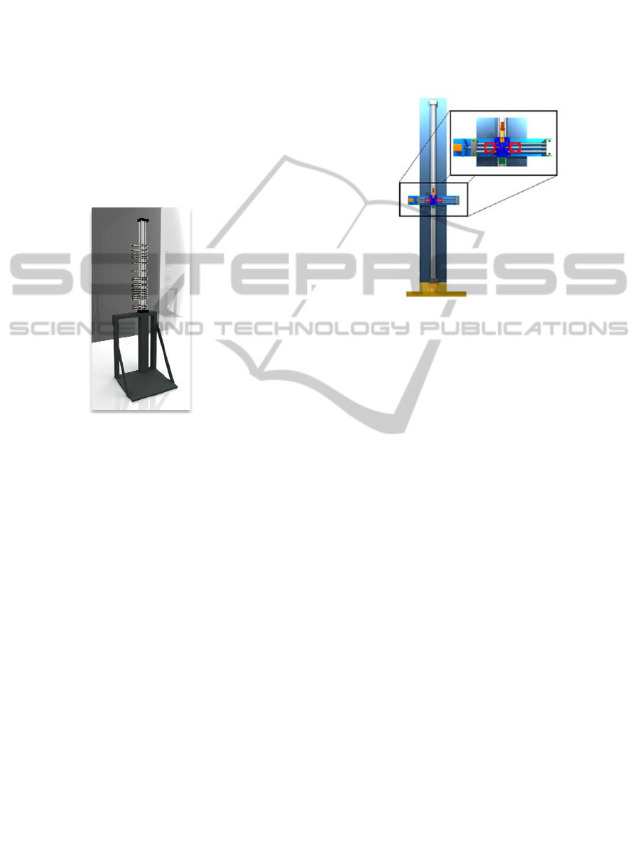
Figure 1: Image of Vertebral Metrics.
Vertebral Metrics (Figure 1) is a non-invasive
mechanical apparatus that was built to identify the
X, Y and Z positions of each vertebra, from the first
cervical vertebra to the first sacral vertebra (Secca,
2008). In a global way Vertebral Metrics evaluates
the curvatures and lateral deviations of the spinal
column in the standing position. (Quaresma, 2009a,
2009b, 2009c)
In the Vertebral Metrics the examiner, starts by
marking on the skin of the person under study the
spinous processes, from the first cervical vertebra to
the first sacral vertebra, using a washable pen. The
evaluation starts by placing the first horizontal piece
in the occipital region. Then it is necessary to move
each piece and place it in line with each mark. In
this device the data collection takes about seven
minutes after the manual marking. (Quaresma,
2009b, 2010)
The aim of this study is to improve the Vertebral
Metrics and take a step forward, performing an
automated measurement of the spine column. With
this new equipment the tests will be faster, simpler
and with a better resolution.
In this new device the same method of tagging
the spinal processes is going to be used, but instead
of a manual measuring, the device will perform it
automatically.
For a better understanding of how the instrument
works, the axis system used will be defined as
following: the transversal distance as our X
coordinate, the antero-posterior distance as the Y
coordinate and the height as Z coordinate.
Figure 2: Aspect of the instrument.
To measure the distance between the device and
the spinal process (Y), a CCD camera, a laser diode
and a lighting system were used. To get an accurate
measurement of the Y distance it is necessary that
the laser spot and the skin mark be coincident. So
this apparatus was assembled over a high precision
X, Z positioner (Figure 2). In order to control the X,
Z movement an image processing software was
develop to find the spinal processes marks and laser
spot, so we can calculate the necessary movements
of the system. When laser spot and spinal process
marks are coincident the system stores the X, Y, Z
coordinates.
When the acquisition is done all the data is
collected by the software and stored it in a single
file, for further offline processing.
2 MECHANICAL SYSTEM – X/Z
POSITIONER
There were two main goals for the mechanical
structure: resolution and speed. The instrument was
constructed based on the following pre-requisites:
- The mechanical system should move all the
hardware necessary for the image acquisition in
two directions, up and down (Z direction), left
and right (X direction).
- Must move 2000 mm in Z and 300 mm in X.
- Resolution must be better than 0.5 mm.
DEVELOPMENT OF VERTEBRAL METRICS - An Instrument to Study the Vertebral Column
225

- Travel speed, must move 1000 mm in Z direction
in 30s (33.3 mm/s).
- Must move in X direction fast enough to position
the camera and laser before the system arrives at
the corresponding Z position.
- Must have a communications protocol controlled
by software.
For the Z positioner a 2 meters DryLin ZLW belt
drive from Igus™ was used. It travels 66 mm per
revolution, and supports speeds up to 5 m/s. The X
positioner is a linear slide table DryLin SHTS Fast.
It has a high helix pitch leadscrew providing high
speed positioner, 50 mm per revolution.
The motors are step by step motor type, for
precision positioning, each step rotates the motor
shaft 0.9
o
, so a full rotation or revolution is 400 steps
(360
o
/ 0.9
o
= 400). For increased torque, motor Z
has a gear box that reduces 7 revolutions to 1 (7:1).
Knowing this we can define the resolution for
the positioners:
Table 1: Resolution of the positioners.
Axe [Step/rev] [mm/rev]
Resolution
[mm/step]
X 400 50 0.125
Z 400*7 = 2800 66 0.024
The selected motors are both from Lin
Engineering™. In terms of Z direction a high torque
bipolar motor, model 5709L-01P with 1 Nm of
maximum torque and 6.25 rev/s maximum speed.
The X motor, is a high torque bipolar motor, model
4209L-01P with 0.35 Nm of maximum torque and
18.75 rev/s maximum speed. Both motors have
independent drivers from Lin Engineering™, model
R325. These drivers provide smooth motor rotation
and micro stepping configuration, also includes Pole
Damping Technology™ (PDT) that enhances step
motor performance by dampening each full step in
order to create a more accurate and smooth motion
profile.
The motion and control of the motors will be
performed by a microcontroller PIC16F877 from
Microchip™. This microprocessor will work with a
16MHz clock and independently generate the two
pulse clocks for step by step motion of the motors. It
will also monitor limit switches, control serial
RS232 communications and control laser and lights
relays.
In terms of RS232 communication a protocol
was developed based on instructions and replies, the
microprocessor will be a slave system, i.e., will only
answer and execute commands from the PC.
Figure 3: Scheme of the communication system.
3 CALCULATION OF DISTANCE
USING THE LASER DIODE
MARK
The laser diode is situated on top of the camera in a
fixed height and angle. Through trigonometric
equations the distance between the equipment and
the individual that is under study can be calculated.
Figure 4: Representation of the measurement of the
antero-posterior distance.
In the Figure 4 the blue lines represent the
viewing angle of the camera and the green line
represents the laser beam.
Knowing the angle of the laser diode, angles of
the camera, the real dimensions of each pixel in the
reference plane (orange plane), as well as the
distance between the reference plane and the focal
centre of the camera, the distance between the laser
diode mark and the focal plane of the camera can be
obtained.
Microprocessor
PIC16F877
Limit switc
h
senso
r
s
Motor Drivers
Relays
RS
232
Motor
Z
Motor
X
BIODEVICES 2011 - International Conference on Biomedical Electronics and Devices
226
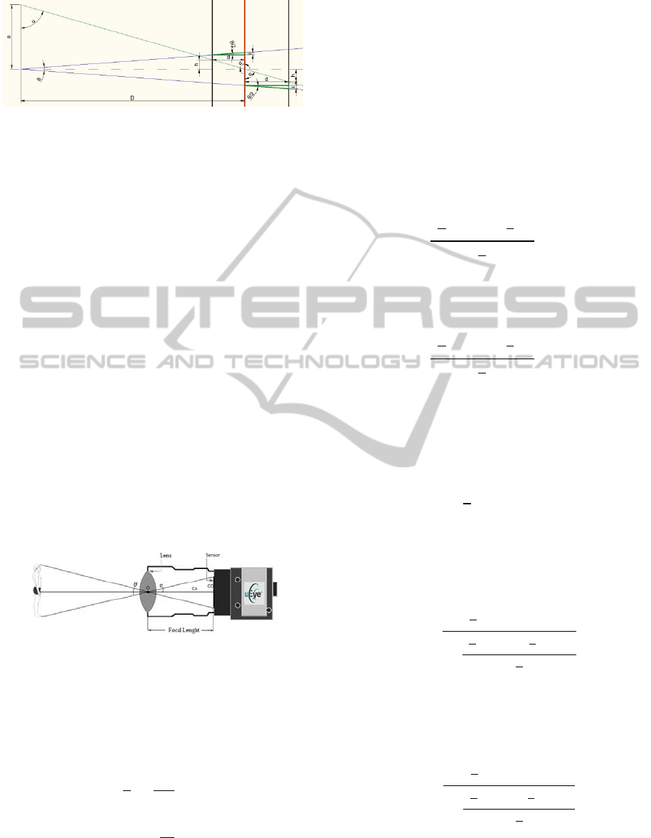
Figure 5: Scheme to demonstrate the calculation of the
Antero-posterior distance.
Distance=D − d
(1)
Distance – Distance between the camera and the
measuring point
D - Distance between the camera focal plane and the
orange plane (reference plane)
d - Variation of distance between the person under
study and the reference plane
The variable d is positive when the plane under
study is on the left of the reference plane otherwise
is negative. The variable d is calculated using
following formula:
d=h×tan(α)
(2)
θ – Vertical viewing angle of the camera
h – Real height of the mark of the laser diode
The viewing angle of a camera is the maximum
angle at which two light beams can intersect at the
secondary focal point (O, Figure 6). In other words,
the viewing angle is the maximum angle of vision of
the camera. The viewing angle depends on the focal
length as well as the dimensions of the sensor. The
viewing angle is higher when the sensor is larger and
when the focal length is lower. (Hecht, 2002)
Figure 6: Representation of the viewing angle of the
camera.
From the observation of Figure 6 the value of the
viewing angle of the camera is obtained through the
following equations:
=2
(3)
tan
2
=
/2
(4)
where:
=2
(
2
) (5)
θ – Viewing angle of the camera
S – Sensor dimension
f – Focal Length
With the viewing angle of the camera and the
distance that the individual under study is from the
reference plane (d), is possible to know the real
dimension of the viewing window of the camera as
well as the real value of each pixel in the plane
under study. The real value of each pixel can be used
to indicate the precise location, to which the
mechanical instrument has to move in order to put
the laser mark on top of the blue points.
To calculate the real value of each pixel for a
specific distance of the subject under study, the
following formula was applied:
P=
R
2
m − tan
2
R
2
(6)
If the pixel coordinate of the laser mark is less than
half of the camera resolution in the vertical axis.
Otherwise P is given by:
P=
R
2
m + tan
2
R
2
(7)
m – Real dimension of the pixel in the reference plane
R – Sensor Resolution
P – Real value of the pixel in the plane under study
Knowing the real pixel dimension is possible to
calculate h.
h=(
R
2
−p)P
(8)
p – Vertical pixel coordinate of the laser
Solving equation 2 in order to d and replace the
result in equation 1, it was found that the distance is
given by:
Distance= D −
R
2
−p m tan
(
α
)
1+
R
2
−ptan
2
tan
(
α
)
R
2
(9)
If the pixel coordinate of the laser mark is less than
half of the camera resolution in the vertical axis.
Otherwise:
Distance=D −
R
2
− p m tan
(
α
)
1−
R
2
−ptan
2
tan
(
α
)
R
2
(10)
If the person under study is at 33 cm from the
equipment, and using a Eye camera model 1440
(resolution 1024x1280) the resolution given by the
DEVELOPMENT OF VERTEBRAL METRICS - An Instrument to Study the Vertebral Column
227
software on the vertical plane is expected to vary
from 0,04 to 0,07 mm, and on the horizontal plane
0,05 to 0,1 mm (value of the pixel).
4 DETECTION OF THE SPINOUS
PROCESSES
To develop the software for detecting spinous
process we used Matlab (MATrix LABoratory, a
numeric computer environment for programming),
where respectively, the processing code and image
analysis, as well as functions for communication
with the mechanical equipment were created.
The first step in the development of the software
to detect the spinous process consisted of choosing
the marker to sign the spinous process in the skin.
For this purpose, several tests were made to find the
best marker, this tests were made to see how the
markers behaved in the skin. It was observed that if
the ink of the marker spread in contact with the skin
the marker could not be used, because the detection
of the point would became harder or could even fail.
The tests showed that skin has mainly the red and
green components in a RBG camera, so the blue will
be the best bet for the marker.
As the processing and image analysis is based on
logical operators, it was necessary to binarize the
image. However, since the processing of the image
in terms of the detection of the points and the laser
mark had to be done in real time and as swiftly as
possible, complex binarization algorithms could not
be used. Therefore, it was decided to make a
binarization by comparing the green and blue
components of the image to detect the blue marks.
This binarization option is the result of tests
performed with the markers. It was observed that
only the area of the blue mark had the blue image
component higher than the green. In other areas of
the skin, the red component of the image dominated,
followed by the green and finally blue. More tests
must be performed to see if this is compatible with
all skin types (Caucasian restricted at this point), but
for now this feature was taken in advantage to make
the image binarization.
An opening operation was applied to the image
in order to reduce the artefacts caused by
binarization. This operation is the result of an
erosion followed by dilatation of the image with the
same mask. This image processing operation keeps
only the structures that are similar to the mask, and
also the ones that are contained within the area of
those same structures.
After this treatment, an algorithm of connected
components (Gonzalez, 2002, 2004) was applied to
the image. This algorithm allows the detection of
objects in binarized images.
Following the detection of objects and using
image analyses the dimensions and centroids of the
objects were calculated. Subsequently, some
comparisons were made to test whether the object
being analyzed is actually the point made by the
marker or not. If the object detected is really a mark,
its coordinates are stored.
The detection of the laser mark is made in a
similar manner to that used in the detection of the
points, yet its binarization is different.
To find the mark position of the laser diode the
red component of the image is compared with the
green component. When the green component has a
higher level than the red component this means that
it is in the area of the laser mark.
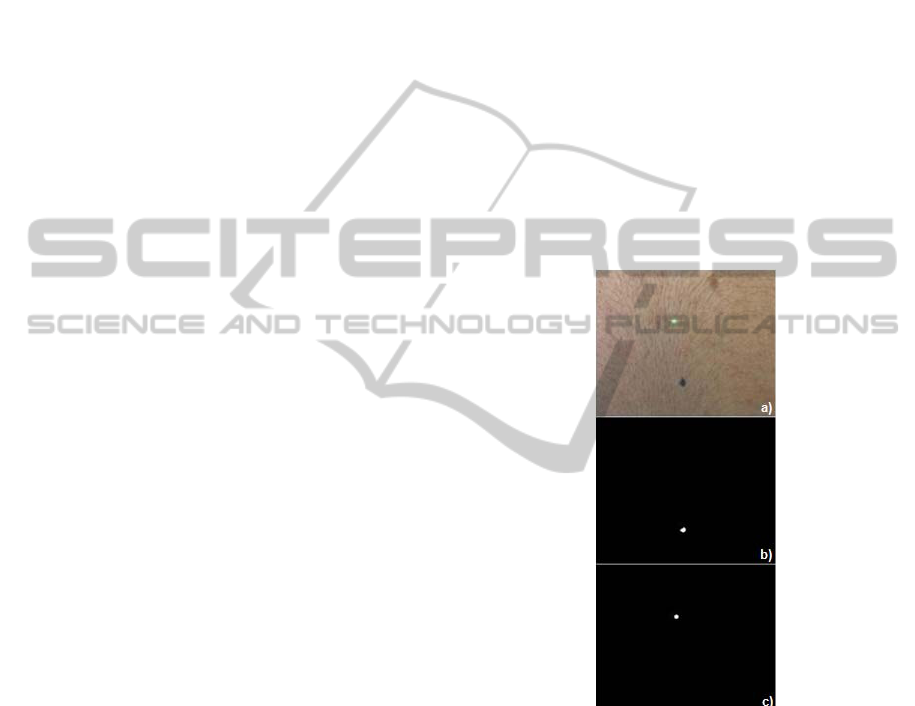
Figure 7: Aspect of the blue and green laser mark on the
skin (a); Binarization plus opening operation of the blue
mark (b); Binarization of the laser mark (c).
In order to move the mechanical equipment to
put the mark of the laser diode on top of the blue
dots it is necessary to calculate the distance from the
laser point to the blue point in pixels and convert it
into real values. For this conversion a reference in
the image is needed, the reference used was the
mark of the laser diode. The mark of the laser diode
was also used to calculate distances allowing us to
calculate the third spatial coordinate of the blue
mark (Muljowidodo K, 2009
).
When the equipment is on the right spot, the
BIODEVICES 2011 - International Conference on Biomedical Electronics and Devices
228

software will store the Y coordinate of the spinal
process and will indicate to the hardware
(mechanical system) the exact moment when it must
save the X and Z coordinates.
5 CONCLUSIONS
This project is still in the test stage, but it already
managed to detect each spinal process in 95 ms and
a complete examination after manual tracing of the
spinal process is taking 2 minutes and 25 seconds.
This time can be improved if the software code is
change for a C language format, most of this time is
being expended in the communication, our goal is to
reach the 30 second mark. The initial intend is to
analyze 25 spinal processes from the first cervical
vertebra to the first sacral vertebra in the standing
position, in the same exam. This option can be
explained by the method used for the manual
marking by palpation and also due to the difficulty
in visualizing the spinal processes that are near the
hair line. In the measurements made with the
equipment it was obtained a maximum error of 1.3
mm in Y, 0.6 mm in X and 0.4 mm in the Z
coordinate, taking into account that the markers have
2 mm in diameter this result is acceptable. However
further tests must be made to improve the detection
of the markers as well as a comparison test to
validate the instrument. At this moment tests are
being made with florescent markers, confident that
this will work for all skin types.
This equipment will allow the possibility of
consecutive sweeps allowing the analysis of the
dynamic postural adjustments of the spine. The
results obtained with this apparatus will allow a
posterior spinal reconstruction in three dimensions
and the calculus of the intervertebral forces. This
instrument will contribute for a detailed study of the
dysfunctions and / or pathologies of the spinal
column.
This device will promote a more efficient and
accurate data acquisition, and it will allow a faster
and simpler mode to study the curvatures and lateral
deviations of the column. The data acquired from the
device can be used in the future to study the
vertebral discs stress and will take a key role in the
biomechanical study of the spinal column.
REFERENCES
Gonzalez, R; Woods, R.; (2002); Digital Image
Processing; (2th ed.) Prentice Hall.
Gonzalez, R.; Woods, R.; Eddins, S.; (2004); Digital
Image Processing using Matlab; Prentice-Hall.
Hecht, E.; (2002); Óptica; (2th ed.) Fundação Calouste
Gulbenkian
Muljowidodo K.; Mochammad A. Rasyid; SaptoAdi N &
Agus Budiyono; (2009); Vision based distance
measurement system using laser pointer design for
underwater vehicle; Indian Journal of Marine Sciences
Vol. 38(3), pp. 324-331
Quaresma, C.; Secca M.; O’Neill J.; Branco J.; (2010);
Vertebral Metrics: Aplication of a Mechanical
Instrument to Evaluate the Spinal Column in Pregnant
Women; International Conference: Biodevice
Quaresma, C.; Secca M.; O’Neill J.; Branco J.; (2009a);
Development of a Mechanical Instrument to Evaluate
Biomechanically the Spinal Column in Pregnant
Women; International Conference: Biodevice, 310-
113.
Quaresma, C.; João, F.; Fonseca, M.; Secca, M.; Veloso,
A.; O’Neill, J.; Branco, J.; (2009b); Validation of
Vertebral Metrics: a mechanical instrument to
evaluate posture of the spinal column; O. Dössel and
W.C. Schlegel (Eds): WC IFMBE Proceedings
25/VII, 711–713.
Quaresma, C.; Secca, M.; O’Neill, J.; Branco, J.; (2009c);
Métrica Vertebral: Instrumento de Avaliação
Biomecânica da Coluna Vertebral; III Congresso
Nacional de Biomecânica.
Secca, M.; Quaresma, C; Santos, F.; (2008); A Mechanical
Instrument to Evaluate Posture of the Spinal Column
in Pregnant Women. In IFMBE Proceedings 4th
European Conference of the International Federation
for Medical and Biological Engineering. 23-27
Vismara L.; Menegoni F.; Zaina F.; Galli M.; Negrini;
Capodaglio S.; (2010); Effect of obesity and low back
pain on spinal mobility: a cross sectional study in
women; Vismera et al. Journal of NeuroEngineering
and Rehabilitation 7:3.
DEVELOPMENT OF VERTEBRAL METRICS - An Instrument to Study the Vertebral Column
229
