
A HIGH ACCURACY CT BASED FEM MODEL
OF THE LUMBAR SPINE TO DETERMINE
ITS BIOMECHANICAL RESPONSE
A. Tsouknidas
Laboratory for Machine Tools and Manufacturing Engineering, Mechanical Engineering Department
Aristoteles University of Thessaloniki, Thessaloniki, Greece
N. Michailidis, S. Savvakis
Physical Metallurgy Laboratory, Mechanical Engineering Department, Aristoteles University of Thessaloniki
Thessaloniki, Greece
K. Anagnostidis
3
rd
Orthopaedic Department ”Papageorgiou” General Hospital, Aristoteles University of Thessaloniki
Thessaloniki, Greece
K.-D. Bouzakis
Laboratory for Machine Tools and Manufacturing Engineering, Mechanical Engineering Department
Aristoteles University of Thessaloniki, Thessaloniki, Greece
G. Kapetanos
3
rd
Orthopaedic Department ”Papageorgiou” General Hospital, Aristoteles University of Thessaloniki
Thessaloniki, Greece
Keywords: Computer Tomography, Lumbar Spine, High Accuracy FEM Model, Biomechanical Response.
Abstract: The lumbar spine is origin of the most frequent complains among all human body parts, since almost 80%
of the population will at some point in life exhibit back related pathologies which in their majority will not
require invasive surgery. Regardless the cause or the development of the problem, the in-depth investigation
of its cause is of the upmost importance during treatment or preoperative evaluation. In this context a model
of the L1-L5 vertebra, capable of accurately assessing the biomechanical response of the lumbar spine
derived from human activity as well as externally induced loads, would be an effective tool during the
examination of normal or clinical conditions. This study presents a CT based FEM model of the lumbar
spine taking into account all function related boundary conditions such as mechanical property anisotropy,
ligaments, contact elements mesh size etc. The developed model is capable of comparing the mechanical
response of a healthy lumbar spine to any given pathology, which can be easily introduced into the model,
thus providing valuable insight on the stress development within the model and predict critical movements
and loads of potential patients.
1 INTRODUCTION
Three dimensional finite element models
representing functional parts of the spine have been
repeatedly introduced over the last years in order to
simulate the biomechanical response of spinal units
(Little et al, 2010, Ezquerro et al, 2004, Wang et al,
2006) or investigate trauma related surgical
treatment (Polikeit et al, 2003, Ashish and Pramod
2009).
Several methods used to obtain the geometrical
characteristics of the investigated set of vertebra
have also been introduced. Even though touch probe
222
Tsouknidas A., Michailidis N., Savvakis S., Anagnostidis K., Bouzakis K. and Kapetanos G..
A HIGH ACCURACY CT BASED FEM MODEL OF THE LUMBAR SPINE TO DETERMINE ITS BIOMECHANICAL RESPONSE .
DOI: 10.5220/0003172102220227
In Proceedings of the International Conference on Bioinformatics Models, Methods and Algorithms (BIOINFORMATICS-2011), pages 222-227
ISBN: 978-989-8425-36-2
Copyright
c
2011 SCITEPRESS (Science and Technology Publications, Lda.)
digitizers (Lee et al, 2002) and laser scanners (Heuer
et al, 2007) are able to provide high accuracy
measurements, thus leading to an accurate
representation of the spine, non intrusive methods
such as CT (Kinder et al, 2009) or nuclear magnetic
resonance (NMR) (Pfirrmann, et al, 2001) ease the
extraction of a patients’ examined areas geometry
while comparing favorably in terms of data
processing and inherent defect determination.
Recent studies have used combinations of the
above techniques to simulate parts of the human
spine ranging from a set of vertebra (Lodygowski et
al, 2005) up to several parts of the spine (Guan et al,
2006). Nevertheless, a high accuracy CT based
model of the lumbar spine with regard to specific
material related properties (directional anisotropy of
the bone, etc.) and all relating connective tissue
(unequal properties distribution among annulus
fibrosus layers, ligaments, contact areas etc.) has to
the best of our knowledge, yet to be introduced. This
exact task is the aim of the present investigation.
2 ANALYTICAL MODEL
2.1 Volume Reconstruction
During the reconstruction of the lumbar spine (L1-
L5) CT were the imaging modality of choice due to
their ability to demonstrate high inherent image
contrast between bone and soft tissue. This enables
relatively unhindered segmentation of the bone from
soft tissue, allowing the generation of a
geometrically accurate volumetric data set of the
patients lumbar spine. The basic concept is to
overlay CT scan slices which represent the outline of
each vertebra with respect to the angulations of the
spines axis (Blankevoort et al., 2008; Beimersade et
al., 2008; Kobayashi et al., 2009). During the
present investigation apatients lumbar spine was
scanned in its entirety from below the lower
boundaries of L1 to the upper limit of L5 ensuring
the full 3D visual representation of the examined
area.
Data acquisition was in accordance to DICOM
(Digital Imaging and Communications in Medicine)
and interpolation of the CT information ensured an
isotropic data set. Although this process did not
result in higher resolution of the reconstructed set of
vertebra, it lead to smoother representation allowing
the distinct removal of the remaining soft tissue in
close proximity to the bone.
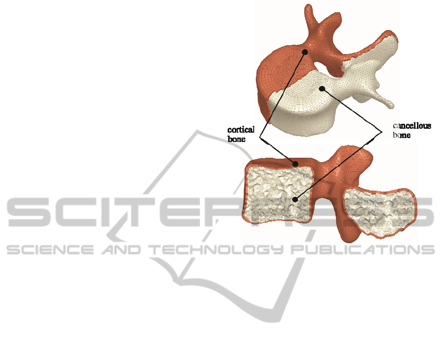
After the representation of the surfaces the
resulting volumes were generated considering an
Figure 1: Resulting mesh of of the L5 vertebra.
outer cortex for each vertebra corresponding to the
cortical bone with a varying thickness of 0.5-1mm
depending on the longitudal slice of volume in the
spines axial direction. The remaining volume of
each vertebra was considered as cancellous bone and
described as such in the way illustrated in Figure 1.
Unlike the aforementioned procedure, the
intervertebral discs of the lumbar spine were reverse
engineered based on the superior and inferior surface
of the connecting vertebral bodies. This method
compares favorably to the regeneration of the discs
based on CT measurements due to the fact that their
volume is characterized by severely altering density
and the inhomogeneous tissue does not facilitate
precise segmentation by imaging techniques. The
geometric characteristics of the intervertebral discs
were designed based on the existing spinal bone
tissue while anatomic data like the inner nucleus
pulposus and the surrounding outer annulus were
considered. The resulting superior and inferior
meshed geometry of every intervertebral disc (see
Figure 2) consists of six spline based layers,
proportional concentric to the outer contour of the
disc, covering a total of 65% of the discs superior
and inferior surface.
2.2 FEM Model
During the meshing of the intervertebral discs,
quadric elements were employed for the annulus
A HIGH ACCURACY CT BASED FEM MODEL OF THE LUMBAR SPINE TO DETERMINE ITS BIOMECHANICAL
RESPONSE
223
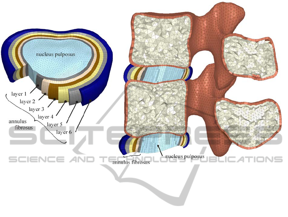
Figure 2: Intervertebral disc reconstruction with nucleus pulposus and the surrounding annulus ground substance.
ground substance in order to facilitate the
implementation of the annulus fibrosus in form of
cable elements positioned crosswise within the
tetrahedron structure ensuring accurate simulation of
their biomechanical response.
The remaining model, nucleus pulposus and
vertebrae, composes of tetra elements (pyramides)
and the unhindered connection at the models contact
areas (quadric- tetra elements interface) was ensured
through the diametrical incision of two triangles in
every rectangle, maintaining the same nodes
throughout the intervertebral disc surface and the
vicinical vertebrae. This approach obviated the
usage of contact elements thus reducing the
processing time of the FEM model.
The mechanical properties of cortical and
cancellous bone were considered as anisotropic (Lu
and Hutton, 1996, Smit et al, 1997) and are
presented in Table 1 along with the strength
characteristics of the nucleus pulposus and the of the
annulus ground substance intervertebral discs.
Among the most important characteristics of the
FEM model was the incorporation of a set of cable
elements, adding valuable mechanical characteristics
to the simulation. The annulus fibrosus was
considered to exhibit varying young modulus for
each set of layer in the radial direction of the
annulus (as presented in Figure 2) in order to reflect
the unequal distribution of this structures properties.
Next to these several other cable elements were
employed representing the remaining connective
tissue between each set of vertebrae, thus ensuring
the precise transition of forces among the vertebra
and simulating the accurate biomechanical response
of the lumbar spine.
Figure 3a demonstrates all aforementioned
connections (ligaments, contact elements and
annulus fibrosus) used as input to the FEM software
(Ansys 12.1 Academic license) as well as a
simplified model (Figure 3b) illustrating only the
cable and contact elements considered during the
simulation.
The mechanical properties as well as the cross
sectional area of each cable element used within the
model (Shirazi-ald et al, 1984, Smit et al, 1997, Lu
and Hutton, 1996) are presented in Table 2. All
cable elements were simulated with Ansys link 10
elements which are capable of receiving only tension
loads resembling the ligaments in a rather accurate
way.
The meshing of the spine segment was
conducted in ANSA of BETA CAE Systems in
order to ensure all above mentioned characteristics
leading to a realistic and isotropic stress transition
within the considered bone and intervertebral disc.
The resulting max. and min. element size as well as
the number of elements for each set of material
considered, are demonstrated in Table 3.
BIOINFORMATICS 2011 - International Conference on Bioinformatics Models, Methods and Algorithms
224
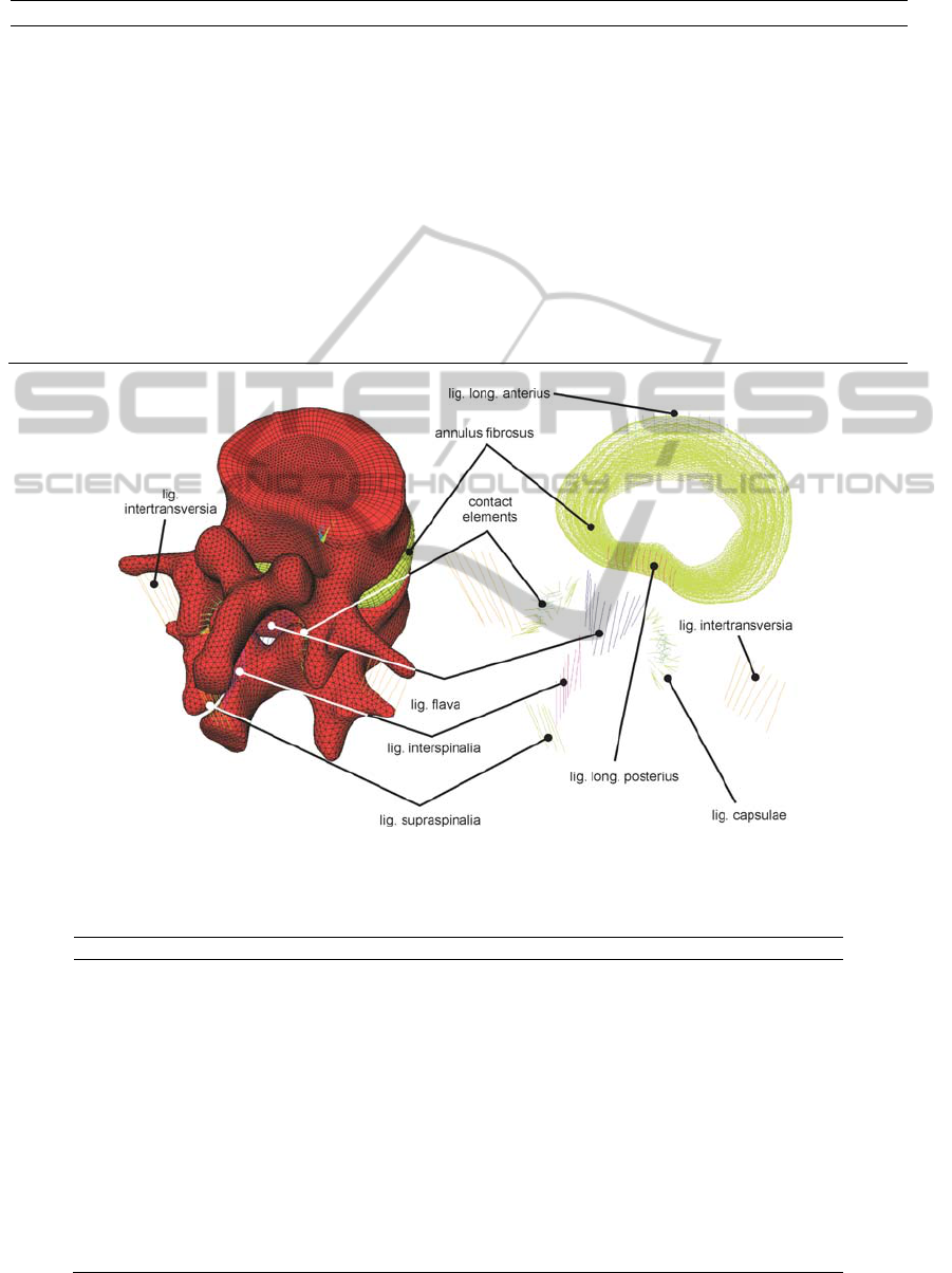
Table 1: Material properties and element specifications of cortical and cancellous bone as well as nucleus pulposus and
annulus ground substance.
Material type Young modulus [Mpa] Poisson ratio Element type used
Cortical bone E
xx
= 11.300 v
x
y
= 0,484 solid 185
E
yy
= 11.300 v
y
z
= 0,203
E
zz
22.000 v
xz
= 0,203
G
x
y
= 3.800
G
y
z
= 5.400
G
xz
= 5.400
Cancellous bone E
xx
= 140 v
x
y
= 0,45 solid 95
E
yy
= 140 v
y
z
= 0,315
E
zz
= 200 v
xz
= 0,315
G
x
y
= 48,3
G
y
z
= 48,3
G
xz
= 48,3
Nucleus pulposus 0,2 v = 0.4999 solid 185
Annulus ground substance 4,2 v = 0.45 solid 185
Figure 3: a) Set of two vertebrae (L4 and L5), intervertebral disc and ligaments b) simplified model without bone and tissue
presenting only ligaments and contact elements.
Table 2: Mechanical properties of ligaments, contact elements and annulus fibrosus layers.
Cable element type Young modulus [Mpa] Poisson ratio Cross-sectional area [mm
2
]
Lig. long. anterius 20 0,3 38
Lig. long. Posterius 70 0,3 20
Lig. flava 50 0,3 60
Lig. intertransversia 50 0,3 10
Lig. interspinalia 28 0,3 35,5
Lig. supraspinalia 28 0,3 35,5
Lig. capsulae 20 0,3 40
Annulus fibrosus layer 1 550 0,45 0,7
Annulus fibrosus layer 2 495 0,45 0,63
Annulus fibrosus layer 3 440 0,45 0,55
Annulus fibrosus layer 4 420 0,45 0,49
Annulus fibrosus layer 5 385 0,45 0,41
Annulus fibrosus layer 6
360
0,45
0,3
A HIGH ACCURACY CT BASED FEM MODEL OF THE LUMBAR SPINE TO DETERMINE ITS BIOMECHANICAL
RESPONSE
225
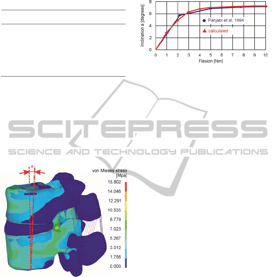
Table 3: Mesh related figures of the lumbar spine model.
Material
type
no. of
Elements
max size
Element
min size
Element
Cortical
bone
87.521 1,78 mm 0,08 mm
Cancellous
bone
712.361 3,04 mm 0,97 mm
Nucleus
pulposus
317.251 2,27 mm 0,72 mm
Annulus 298.657 3,71 mm 1,87 mm
3 RESULTS
The validation of the model was based on torsion,
extension, flextion, left and right bending
simulations to determine the resulting inclination of
spine segments under specific loads and compare
those to experimental values found in literature
(Panjabi et al, 1994). Figure 4 demonstrates the
developing stress distribution of the examined set
and intervertebral disc for a 10Nm flexion moment.
Figure 4: Calculated stress distribution on a set of L2-L3
vertebrae subjected to extension.
Figure 5 exhibits that the load induced response of
the vertebra is almost identical to its experimentally
determined one.
Figure 5: Calculated and experimental load-inclination
diagram.
4 CONCLUSIONS
The introduced model facilitates the evaluation of
induced loads on the lumbar spine. Pathological
defects, trauma as well as therapy oriented
intervention can be assessed prior to the actual
practice on the patient. This model may also be a
valuable tool in preoperative evaluation of the
biomechanical response of the system to a function
specific implant.
ACKNOWLEDGEMENTS
The authors would like to thank BETA CAE
Systems SA for providing them with the CAE pre-
processor ANSA, used during surface and volume
generation and meshing of the introduced model.
REFERENCES
Little, J. P., Pearcy, M. J., Tevelen, G., Evans, J. H.,
Pettet, G., Adam, C. J., 2010, The mechanical
response of the ovine lumbar anulus fibrosus to
uniaxial, biaxial and shear loads, Journal of the
Mechanical Behavior of Biomedical Materials, 3, 146-157
Ezquerro, F., Simón, A., Prado, M., Pérez, A., 2004,
Combination of finite element modeling and
optimization for the study of lumbar spine
biomechanics considering the 3D thorax–pelvis
orientation, Medical Engineering & Physics, 26(1),
11-22
Wang, J. P., Zhong, Z C., Cheng, C. K., Chen, C. S., Yu,
C. H., Chang, T.K., Wei, S.H., 2006, Finite element
analysis of the spondylolysis in lumbar spine., Biomed
Mater Eng.16(5), 301-308.
Polikeit, A., Ferguson, S.J., Nolte, L.P., Orr, T.E., 2003,
Factors influencing stresses in the lumbar spine after
the insertion of intervertebral cages: finite element
analysis. Eur Spine J., 12(4):413-20
BIOINFORMATICS 2011 - International Conference on Bioinformatics Models, Methods and Algorithms
226

Ashish, D., Pramod, P,, 2009, Development of Computer
Aided 3D Model From Computed Tomography
Images and its Finite Element Analysis for Lumbar
Interbody Fusion with Instrumentation, International
Journal of CAD/CAM 9(1) 121-128
Lee, K. K. Teo, E. C. Qiu, T. X. Ng, H. W. and Yang, K.,
2003, Finite element modeling of L2-L3 using
digitizer,” Int. J. Computer Application Technology
(IJCAT) (Special issue on Biomedical Engineering
and I.T.) 20 1-9
Heuer, F., Schmidt, H., Claes, L., Wilke, H. J., 2008, A
new laser scanning technique for imaging
intervertebral disc displacement and its application to
modeling nucleotomy, Arthroscopy: The Journal of
Arthroscopic and Related Surgery 23(3) 260-269
Klinder, T., Ostermann, J., Ehm, M., Franz, A., Kneser,
R., Lorenz, C., 2009, Automated model-based vertebra
detection, identification, and segmentation in CT
images, Medical Image Analysis 13, 471–482
Pfirrmann, C., Metzdorf, A., Zanetti, M., Hodler, J., Boos,
N., 2001, Magnetic Resonance Classification of
Lumbar Intervertebral Disc Degeneration, SPINE
26(17), 1873–1878
Lodygowsky, T., Kakol, W., ierszycki, M., 2005, Three-
dimensional nonlinear finite element model of the
human lumbar spine segment, Acta of Bioengineering
and Biomechanics 7(2)
Guan, Y., Yoganandan, N., Zhang, J., Pintar, F., Cusick,
J., Wolfla, C., Maiman, D., 2006, Validation of a
clinical finite element model of the human
lumbosacral spine, Med Bio Eng Comput 44, 633–641
Blankevoort, L., Beimers, L., Jonges, R., Valstar, E.R.,
Tuijthof, G.J.M., 2008. The accuracy of a CT-based
bone segmentation technique for measuring the range
of motion of the joints in the ankle. J. Foot Ankle Res.
1, O34
Beimersade, L., Tuijthofde, G.J.M., Blankevoortde, L.
Jonges. R., Maas, M., Van Dijk, C.N., 2008. In-vivo
range of motion of the subtalar joint using computed
tomography, J. Biomech. 41, 1390-1397
Kobayashi, K., Odagawa, K., Sakamoto, M., Tanabe, Y.,
2009. Accuracy of Single Plane X-Ray Image-Based
Technique for Assessment of Knee Kinematics,
Journal of Biomechanical Science and Engineering 4,
192-200
Lu, Y.M, Hutton, W.C, Gharpuray, V.M., 1996, Do
bending, twisting and diurnal fluid change in the disc
affect the propensity to prolapse? A viscoelastic finite
element model. Spine, 21,2570-2579.
Smit, T. H., Odgaard, A., Schneider, E., 1997, Structure
and function of vertebral trabecular bone. Spine
15;22(24), 2823-2833.
Shirazi-Adl, S.A., Shrivastava, S.C., Ahmed, A.M., 1984,
Stress analysis of the lumbar disc-body unit in
compression. A three-dimensional nonlinear finite
element study. Spine 9(2),120-34
A HIGH ACCURACY CT BASED FEM MODEL OF THE LUMBAR SPINE TO DETERMINE ITS BIOMECHANICAL
RESPONSE
227
