
PETRI NET BASED AGENTS FOR COORDINATING RESOURCES
IN A WORKFLOW MANAGEMENT SYSTEM
Albert Pl
`
a, Pablo Gay, Joaquim Mel
´
endez and Beatriz L
´
opez
University of Girona, Campus Montilivi, P4 building, 17003 Girona, Spain
Keywords:
Workflow modeling, Workflow monitoring, Petri nets, Resources, Delay prediction.
Abstract:
We present a new framework for business process management based in a Petri net extension called Resource-
Aware Petri Nets. This extension considers resources representation at the application level and allows the
monitoring of the whole system with its dependencies. Thus, to solve resource usage conflict, agents are
proposed to take care of monitoring workflow instances. This new comprehension of dependencies also allows
the creation of a delay prediction system based in historical data from the workflows itself. In this paper we
expose our methodology for modeling workflows through our extension which is based in classical approaches.
Also a monitoring and delay prediction workflow is introduced and analyzed. In order to test our approach,
we have extracted workflows from real cases and tested our framework simulating different kind of situations
and resources, getting promising results since our prototype can provide early detection of workflows delays.
1 INTRODUCTION
Nowadays business process management is becoming
a fundamental piece in many industrial processes. In
today’s economy, suppliers, manufactures and retail-
ers are working together in order to reduce the pro-
duction costs and to maximize the productivity. To
manage the evolution and the interactions of the busi-
ness actions it is important to accurately model the
steps to follow in the process, the resources needed
and the flow of the messages between the differ-
ent parts involved (suppliers, manufacturers, clients,
etc.). Workflows (WFs) provide a way of describing
the order of execution and the dependent relationships
between the constituting activities of the business pro-
cesses.
Workflows usually model single and unique busi-
ness processes, nevertheless, in real life environ-
ments, processes represented by workflows are rarely
executed individually. Workflows are usually exe-
cuted concurrently, sharing a limited number of re-
sources sometimes even with external processes. In
consequence, a delay in an ongoing workflow can im-
pact other pending workflows, causing a cascade ef-
fect in the performance of the rest of the system due
to dependencies or to resource occupation. For this
reason it is important to monitor not only a single
workflow execution, but also the whole system, as a
delay can echo in the rest of executions. Conversely
to previous works, the focus of this work is studying
monitoring methods to deal with all the workflows in
a environment (at the organization level). Monitoring
means that the workflow management system (WMS)
is aware of the states of the whole system regarding
the current workflows actives and the resources avail-
able to carry them out.
Moreover, an intelligent monitoring methodology
should be able to avoid, or somehow, reduce the ef-
fects of unexpected behaviors, so, corrective and pre-
ventive strategies are needed.
Regarding corrective strategies, when a workflow
deadline is reached or close to be reached, a time out
message or a running out of time alarm should be
fired. For example, in (Blake, 2005), the authors pro-
vide a supporting tool to the user in order to mod-
ify running workflows Regarding preventive strate-
gies, WMS should be able to predict when a work-
flow will fail before it happens. Preventive strategies
are important as when a WF exceeds a deadline can
cause important problems in the system. In critical
domains, such as medical device maintenance, a de-
lay in a workflow could involve the unavailability of
medical equipment causing delays on hospital oper-
ations, delays in surgeries and actually impacting on
patients health.
In this line, the research on Artificial Intelligence
514
Plà A., Gay P., Meléndez J. and López B..
PETRI NET BASED AGENTS FOR COORDINATING RESOURCES IN A WORKFLOW MANAGEMENT SYSTEM.
DOI: 10.5220/0003196405140523
In Proceedings of the 3rd International Conference on Agents and Artificial Intelligence (ICAART-2011), pages 514-523
ISBN: 978-989-8425-40-9
Copyright
c
2011 SCITEPRESS (Science and Technology Publications, Lda.)

Figure 1: a) Petri net routing sequence. b) Petri net choice.
c) Petri net parallel execution. d) Petri net iteration.
have been centered in including new intelligent ca-
pabilities to WMS. E.g. CAKE (Bergmann et al.,
2006) takes benefit of case based reasoning to im-
prove workflow architectures and to increase the col-
laboration among them. Regarding the agent commu-
nity, they are also interested in workflows but empha-
sizing its use for agent coordination.
Our work concerns both, Artificial Intelligence
and agents, as provides intelligent capabilities to
WMS for monitoring concurrent workflows. We ex-
tend previous Petri net models in order to add re-
source representation at the application level (instead
of the workflow level, i.e. the resource required to
develop a service or a task). We call them resource-
aware Petri nets. This petri net extension allows us
to monitor the state of all the running workflows of
the system using agents. Resource-aware Petri nets
(RAPN) also permit to predict possible delays without
waiting until the workflow deadline so corrective and
preventive strategies can be applied. Regarding the
monitoring phase, we present an agent-based WMS
which monitors workflows sharing resources inside
an organization by individually monitoring the differ-
ent workflows but using the whole environment infor-
mation to diagnose the reason of unexpected or ab-
normal behaviors.
2 RELATED WORK
The lack of standardization in workflow representa-
tion has been a trending research topic during the
last years. This absence of unification has led to a
highly diversified types of workflow representations.
Some authors use other fields’ representation mod-
els such as UML activity diagrams (Kalnins and Vi-
tolins, 2006), Business Process Management Nota-
tion (Muehlen and Recker, 2008) (BPMN) or dif-
ferent types of petri nets (called WF-nets) (Rinderle
et al., 2004; Van der Aalst et al., 2003). Other re-
searchers have chosen to develop specific languages
for workflow representation such as YAWL (Brogi
et al., 2006).
Regarding the resource representation in work-
flows, despite some languages such as the mentioned
UML provide tools for representing resources itself,
many workflow modeling languages do not integrate
resources into its representations. A recent work on
workflow representations that we should take into ac-
count is (Lombardi and Milano, 2010) which pro-
poses the condition task graphs (CTGs). In a CTG,
the arcs are labeled with probabilities. Tasks have re-
sources associated. But due to the nature of the con-
ditional branch of the graphs, the particular resources
requirements for the execution of a given workflow
can vary. Then the authors propose a methodology to
optimize the resources requirements. From our per-
spective, such conditional representations could also
be used for monitoring, without the need of specific
workflow management system. The authors point out
in their future work that their current research con-
cerns the applicability of their approach to BPM.
Workflow monitoring has also been studied from
different points of view. E.g. Van der Aalst et
al.(Van der Aalst and Pesic, 2006) combine Petri nets
(used to model the behavior of a service flow) and
event logs (used to model real behavior of a service
flow) in order to detect deviations and to store data
for a further mining process. Then, in (Rozinat et al.,
2009) the historical data is used for simulation, so that
a short time projection can be obtained on the work-
flow outcomes.
As for the use of Petri nets for workflow moni-
toring, Frankowiak et al.(Frankowiak et al., 2009) de-
veloped a micro controller-based process monitoring
in order to control the correct procedure of a manu-
facturing chain where every Petri net transition was
linked to a micro controller input. The logistic field
has also been a hot research topic when it comes to
Petri net monitoring(Van der Aalst, 1993).
Other previous related works regarding to work-
flows monitoring come from the multi-agent commu-
nity. For example, in (Wang and Wang, 2002) a multi-
agent system is proposed to monitor the workflows
associated to a given business process, so that they
improve the system capabilities to deal with changes
in the environment. In (Zarour et al., 2005) an agent
based system is also proposed to deal with coordina-
tion and management of workflows between virtual
enterprises.
3 BACKGROUND
In this paper high level Petri nets are used to model
and monitor workflow services. For this reason, in the
next paragraphs we introduce basic Petri net notation
and terminology, which were presented by C.A. Petri
PETRI NET BASED AGENTS FOR COORDINATING RESOURCES IN A WORKFLOW MANAGEMENT SYSTEM
515

(Petri, 1962).
The simple or classical Petri net can be defined
as a directed bipartite graph with two kind of nodes
called places and transitions which are connected by
arcs. A place p is called an input place of transition t
if exists an arc that directly connects p to t. A place p
is called an output place of transition t if exists an arc
that directly connects t to p. Moreover, arcs cannot
connect two nodes of the same class. Places can con-
tain tokens. During the Petri net execution, the posi-
tion and number of tokens may vary. In the graphical
representation places are drawn as circles, transitions
are rectangles or bars, tokens are represented black
dots and arcs by arrows (see Figure 1).
A transition t is enabled when each input place
p of t contains one or more tokens. An enabled tran-
sition can be fired. Firing the transition t erases one
token from t input place and creates a new one to its
output place. The state of a Petri net is defined by the
distribution of its tokens along the net, this can also
be referred as marking. More information about Petri
nets bases and history can be found in (Murata, 2002).
In order to include different domain particulari-
ties such as time or priorities, Petri nets have been en-
riched with extensions which represent theses differ-
ent domain particularities. This new kind of nets were
called high level Petri nets. In the classical Petri net,
tokens have no kind of information incorporated, in
consequence, it is impossible to distinguish between
them. In practical terms, if a token corresponds to
the status of real-life workflow, when two tokens are
inside the same Petri net there is no possibility to re-
late each token with its correspondent flow. Using
the classical representation, the only way to discern
between both tokens/process is to duplicate the Petri
net and to put each token in the different nets, which
presents a problem for real process modeling as when
different kinds of processes appear into a workflow,
the size of the Petri net increases significantly. In or-
der to avoid this duplication, the colored Petri net ex-
tension was created(Van der Aalst, 1993). Colored
Petri nets assign a type or an identifier to each token
so the confusion between tokens disappears.
Another common extension for the classical Petri
nets is the inclusion of time which can be included in
different ways. Transition-timed (T-timed) Petri nets
(PN) associate time to the transition. In T-timed PN
An interval of time can be assigned to each transition
and they can only fire during this time interval, there-
fore, tokens remains at the input places at least until
this time arrives. Place-timed PN associate time ts
i
to the places. This means that when a token t arrives
to a place p it must stay there at least ts
p
time units
although its transition fires. Finally, token-timed PN
(or dense-timed PN)(Abdulla et al., 2006) is an ex-
tension of Petri nets in which each token is equipped
with a real-valued clock so the time spent for every to-
ken can be registered. In this article, when timed Petri
nets are mentioned is referring to this token-timed PN
extension.
4 AGENT-BASED WORKFLOW
MANAGEMENT SYSTEM
Our system is based on Petri nets for workflow mod-
eling, taking into account the existing resources in the
system. Workflows and resources are handled by the
workflow management system (WMS), as shown in
Figure 2. The main components of the WMS is the
Monitoring System (MS) which is responsible of link-
ing the WMS with the modeled process and also of
monitoring the evolution of the workflow. The WMS
access to the following data:
• Library of workflow models, which contains an
archive of the workflows modeling the business
processes of an organization or corporation.
• Resource data base, which stores the information
related to the available resources of the system
(type of resource, status, amount, etc.).
• Running workflows memory, which contains the
state of the workflows currently running in the
system.
With this information the WMS uses the following
methodology to start and to monitor workflows:
1. Receives a request for a business activity A
i
2. Search in the workflow library for the pattern as-
sociated to A
i
, Pattern(A
i
) = W f
i
.
3. If W f i is not running with other parameters in the
WMS, then the WMS loads the workflow from the
workflow library.
4. A new token t
i
is created and placed into the cor-
responding workflow.
The key issue and the main contribution of this work
concerns how workflows and resources are modeled
using Petri nets and monitored by agents. The work-
flow modeling and monitoring are detailed below.
4.1 Workflow Modeling
Workflow modeling using high level Petri nets has
been broadly studied among last years(Eshuis and
Dehnert, 2003; Van der Aalst, 1998). As figure 1
shows Petri nets can represent typical workflow be-
haviors like sequential routings, parallel executions,
ICAART 2011 - 3rd International Conference on Agents and Artificial Intelligence
516
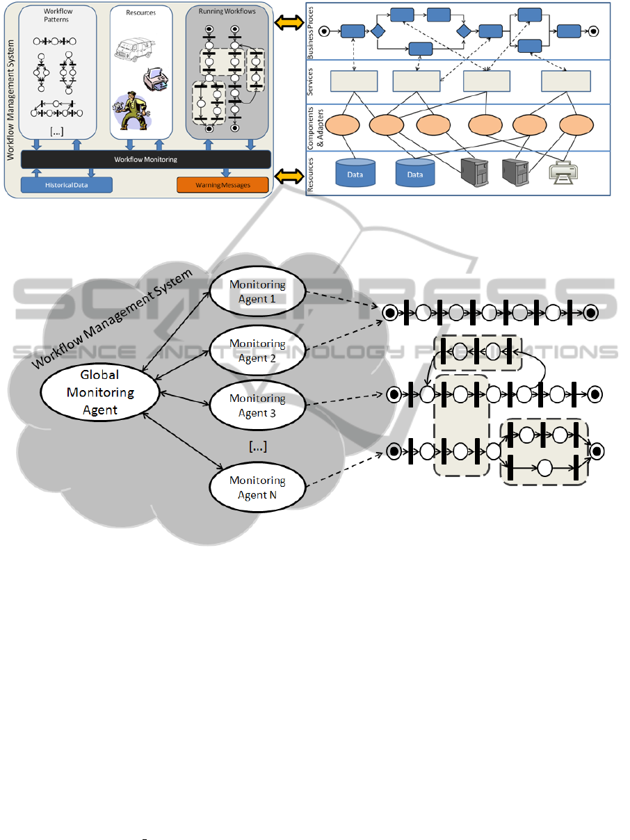
Figure 2: The workflow management system is responsible for modeling and monitoring the workflow and sends warnings
when a possible delay is detected.
Figure 3: The workflow management system is responsible for modeling and monitoring the workflow and sends warnings
when a possible delay is detected.
choices, iterations, etc. Modeling a workflow with a
Petri net is a simple task but it can take a long time
as all the situations and details must be taken into ac-
count.
Definition 1. A Petri net is a 3-tuple
h
P,T, A
i
where
• P is a finite set of Places
• T is a finite set of Transitions
• P ∩ T =
/
0
• A is the set of arcs which connect P with T and
vice versa. A : (P × T ) ∪ (T × P)
When modeling a workflow with PN, the most
common type of transition is the one which represents
tasks or services (e.g. send message), it is fired just at
the moment where the activity starts. When transi-
tions represent the making of a decision they do not
start any new service, they just chose if a path must
be followed or not and they are fired by the system
(or by the actor which takes the decision). External
events (e.g. user inserts a coin into a printer) are also
represented as transitions. The firing of the transition
occurs when the event happens. Finally some tran-
sitions are just used for routing tasks (e.g. throw a
concurrent execution of processes) and they are fired
by the system. It is important to notice that there ex-
ists some dependencies between different transition
types: a decision type transition always comes after a
service type one; decision type transitions never come
alone, there must be at least two complementary de-
cisions so the WF net is path complete.
As mentioned above, in WF nets places repre-
sents conditions (some authors refers to conditions as
states). A place indicates the status and the conditions
PETRI NET BASED AGENTS FOR COORDINATING RESOURCES IN A WORKFLOW MANAGEMENT SYSTEM
517

of a workflow in a concrete point, in other words, a
place p is the pre-condition of its input transition and
a place p is the post-condition of its output transition.
Finally, in WF nets, tokens (which are colored)
represent cases. Every time a token appears in the
input place i means that a business new process p has
started inside the workflow. Tokens are colored so the
processes can be distinguished
Our work is specially focused on delays predic-
tion, conversely, we need to take care of the kind
and number of resources needed for every task inside
the workflow so we can evaluate the time workflows
will spend waiting for an available resource. In or-
der to satisfy this requirement we extended the work-
flow net representation with a new resource element.
We called this extension resource-aware Petri nets
(RAPN, Definition 5). RAPN incorporate resources
to high level Petri nets(Abdulla et al., 2006). Re-
sources (Definition 2) are related with sets of con-
secutive transitions (forming subpaths, Definition 3)
where the first transition (t
s
) is the one which allo-
cates the resource and the last (t
e
) is the one which
releases it. If there are not available resources of the
required type by a transition (t
s
) this transition cannot
be fired until a resource of the desired type is released.
Definition 2. A Resource is defined as a tuple
h
r,Q
i
where r is the kind of resource and Q the amount of re-
sources of type r available in the system. Therefore R
is a finite set of resources. R =
{h
r
1
,Q
1
i
,...
h
r
n
,Q
n
i}
where n stands for the resources cardinal.
Definition 3. A Transition Subpath (TS) is the set of
connected nodes between two transitions where t
s
is
the starting transition of the subpath and t
e
the last
one, TS =
h
t
s
,t
e
i
.
Definition 4. A transition subpath resource depen-
dence (SD) defines the dependence between all the
nodes of a subpath TS
i
and a set of resources, SD =
T S
i
,
r
j
,k
j
where k
j
is the amount of resources
of type r
j
needed.
Definition 5. A Resource-aware Petri net is a 6-tuple
h
P,T, A,T O,R,D
i
where
• P is a finite set of places
• T is a finite set of transitions
• P ∩ T =
/
0
• A is the set of arcs which connect P with T and
vice versa A : (P × T ) ∪ (T × P)
• TO is a finite set of tokens which can store time
information
• R is a finite set of Resources
• D is a finite set of transition subpath resource de-
pendencies (SD)
Figure 4: Delays in a workflow execution are estimated us-
ing the token information, the transition mean times and the
workflow state.
• There exists an input place ”i” and an output
place ”o” where:
– Place i does not have any incoming arc.
– Place o does not have any outcoming arc
– Each node n ∈ P ∪ T where n 6= i & n 6= o has
a path to o
– Each node n ∈ P ∪ T where n 6= i & n 6= o has
a path from i
4.2 Workflow Monitoring
Monitoring can be performed both at workflow and
task level. Monitoring at the workflow level means
that it is necessary to compare the evolution of the
monitored workflow instance with the standard be-
havior of the generic workflow. Every time a new
instance is started, a maximum deadline for the case
resolution is assigned to it. When the workflow time
execution is near the deadline, a warning message is
send. However those warnings tend to arrive at the
late phase of the workflow (even if they are caused
for an early delay) so a restructuration of the work-
flow or resource addition may be difficult to imple-
ment. We consider than a lower-level monitoring of
the workflow, in a task level, would result in an earlier
detection of the delay.
For that purpose, we define the MS as a multiagent
system with two different kinds of agents: monitor-
ing agents which are responsible of collecting infor-
mation about the development of a single workflow
instance; and a global monitoring agent which is in
charge of deciding if the different workflows are sus-
ceptible of suffering a delay or not.
In our approach, besides the global execution time
of the workflow, we monitor the time that tokens
spend on each place. Every time a workflow is in-
stantiated, a monitoring agent (Figure 3) which can
controls the information involving both the token and
the workflow is thrown. The agent detect possible de-
lays in the workflow (Figure 4) as it can notice when
a task is exceeding it’s estimated execution time. As
a delay in the execution of a task does not necessar-
ily represents a delay in the workflow execution, the
monitoring agent uses the information stored on the
ICAART 2011 - 3rd International Conference on Agents and Artificial Intelligence
518
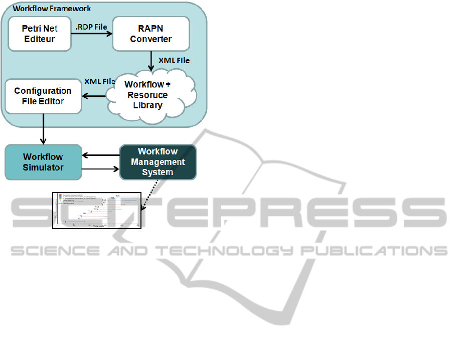
Figure 5: Architecture of the workflow simulation frame-
work.
token and the time required to execute the remaining
workflow to decide if the workflow is susceptible to
suffer a delay (Pla, 2010).
As the monitoring agents only have information of
a single workflow, when a possible delay is detected,
the agents send a warning message to the global mon-
itoring agent. As several monitoring agents can be
sending similar warning messages regarding a related
problem (e.g. the lack of a concrete type of resource
or a neck bottle in the workflow interaction design),
the global monitoring agent is responsible for inter-
preting the different incoming messages. For that pur-
pose it is endowed with a Complex Event Processing
engine which reasons what is happening in the global
workflow environment and tries to diagnose the rea-
son of the delays (Gay et al., 2010), sending the cor-
responding alarms when necessary.
These alarms allow system supervisors to restruc-
ture the workflow or to endow the system with more
resources in order to avoid the delays. Moreover, the
study of these warnings with data mining and statis-
tical techniques can offer information about the per-
formance of the services and to detect which are the
weaker points of the architecture.
5 RESULTS
This first prototype of our work consists in 3 mod-
ules: a workflow framework, a workflow simulation
engine and the workflow management system (Fig-
ure 5). The workflow framework can load Petri nets
defined by XML or load Petri nets designed with the
PM Editeur(Zdenk et al., 2001) graphical editor; it is
responsible for firing transitions, moving tokens along
the Petri net and all the work related with Petri nets.
Moreover it allows the user to define resources and
to associate them with different parts of the Petri net.
The workflow simulation engine permits to recreate
the evolution of a workflow, given a set of parameters
(the workflow modeling, the probability of a work in-
stantiation, the standard deviation in the execution of
a time and, number of resources in the system and the
duration of the simulation) it simulates the execution
of the workflow. Finally the workflow management
system is responsible for monitoring the evolution of
the workflow, detecting possible delays and to ask the
workflow motor to trigger the transitions.
5.1 Experimental Setup
To test the performance of our system we modeled
and simulated a set of workflows extracted from the
AIMES project(AIMESproject, 2010). The work-
flows correspond to common activities in the med-
ical device maintenance industry such as assigning
a technician for a device repairing or reassigning a
technician. Specifically the used workflows are Reac-
tive Maintenance Interventions (RMI), Maintenance
Event Escalation Management (MEEM) and Inven-
tory and Installation of New Equipment (IINE).
The first one, RMI, describes the procedure to
follow when a medical device throws a maintenance
warning. In this case the system catch the warning
and classifies the action, locates the source of the ac-
tion, assigns a priority to the task and assigns the
maintenance action to a technician. Finally the tech-
nician carries the action and the work ow finalizes.
This workflow is composed by six tasks or services.
In this case, the resources needed to accomplish the
workflow are technicians of a concrete type.
In MEEM the technical staff leader wants to as-
sign a concrete task to an available technician. First of
all, the staff leader looks which technicians are avail-
able and which tasks have not been assigned; then the
staff leader defines a procedure to follow for a techni-
cian and finally the technician performs the assigned
task (5 tasks). In this workflow two kinds of resources
interfere in the development: the technical staff leader
(which its amount will be always one as there is only
one leader in each group) and technicians of a con-
crete type.
Finally, IINE describes the established procedure
to follow when a new device arrives to a hospital.
PETRI NET BASED AGENTS FOR COORDINATING RESOURCES IN A WORKFLOW MANAGEMENT SYSTEM
519
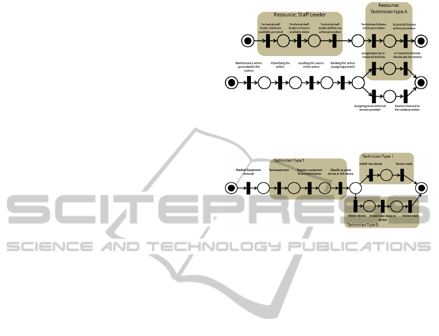
Firstly, a testing specialized technician makes the
quality tests in order to check the proper working of
the device and that all its documentation is attached,
then the equipment is registered and installed. If the
received equipment is a piece for an existing device
an specialized technician embeds the equipment to its
correspondent device, otherwise, an installer mounts
the device where it corresponds. Nine different tasks
are required for this workflow and three different kind
of resources (although only two will be used at each
instantiation).
Combining these workflows we performed exper-
iments in three different scenarios. In the first one
RMI and MEEM are simultaneously executed. We
only defined two kind of resources: Technical staff
leader (1 in the system) and Technician type A (4
in the system); This scenario allows us to study the
behavior of our methods in a simple experiment. In
the second scenario a new workflow is added in the
system: a MEEM requiring a technician of type B.
In consequence, a new type of resource was added
(Technician type B) and the rest of resources is mod-
ified: 1 Technical staff leader, 3 Technician type A
and 1 B. The aim of this experiment is to study the
performance of the workflow management system in
a more complex scenario. Finally, in the third sce-
nario, the three defined workflows are used. In it, we
considered the type D technician as the same which
appears in the RMI and in the MEEM. As technician
D is used by all the workflows we considered to in-
clude a high number of this type available resources in
the system, having 5 type D technicians, 1 staff leader
(used by MEEM) and 2 type I and T technicians (used
by IINE). This scenario allows us to study the work-
flow management system when many resources are
involved in the business processes. In all the scenarios
we have simulated an interval of 500 time units with a
workflow starting probability p = 0.05 per time unit.
In the first two scenarios, the kind of WF created was
randomly chosen with the same probability for each
WF type, while in the last one the probabilities are
3/6 for RMI, 2/6 for IINE and 1/6 for MEEM.
5.2 Results
The obtained results are shown as a flow execution
diagram. The delayed workflows appear marked with
their token identifier. The workflow executions are
represented as lines where the dashed lines represents
a normal execution (inside its maximum time of exe-
cution) and information of delayed plans are shown as
solid lines. Moreover, the instants in which our tool
predicted a delay for the workflow are marked with a
vertical line.
Figure 6: Top: Maintenance event escalation management.
Bottom: Reactive maintenance intervention.
Figure 7: Inventory and Installation of New Equipment.
Figure 8 shows the first scenario result. In this
experiment two different workflows are sharing two
different resources. The simulation among 500 time
units generated 30 workflow cases where 7 of them
resulted in a delay (T1, T8, T10, T15, T19, T22 and
T26). All of them were predicted before they oc-
curred by our system although 2 false positives (a de-
lay was predicted but the workflow ended on time)
were also predicted (T5 and T11). As it is a simple
scenario the number of delays produced is small.
Figure 9 shows the second scenario result where
the same two workflows share 3 different types of re-
sources with a different quantity of them. The simu-
lation generated 31 workflow cases where 10 finished
out of time (T7, T9, T12, T15, T16, T17, T19, T20,
T25 and T29). As happened on the previous scenario
all the delays were successfully predicted, neverthe-
less, 2 on time workflows where classified as delayed
workflows (T1 and T12). Moreover, due to the higher
complexity of this experiment, it is important to no-
tice that the number of delays respect the first scenario
has increased.
Finally Figure 10 the results of the thirds scenario
are shown. In it, the installation and inventory of new
equipment is added to the first scenario. In the sim-
ulation 26 workflows have been instantiated and 12
of them have been marked as possible delayed work-
flows (T9, T11, T13, T14, T15, T16, T17, T18, T19,
T21, T22 and T24). As both the complexity and the
number of resources used in this scenario are higher
than in the previous ones, the number of delays in
ICAART 2011 - 3rd International Conference on Agents and Artificial Intelligence
520
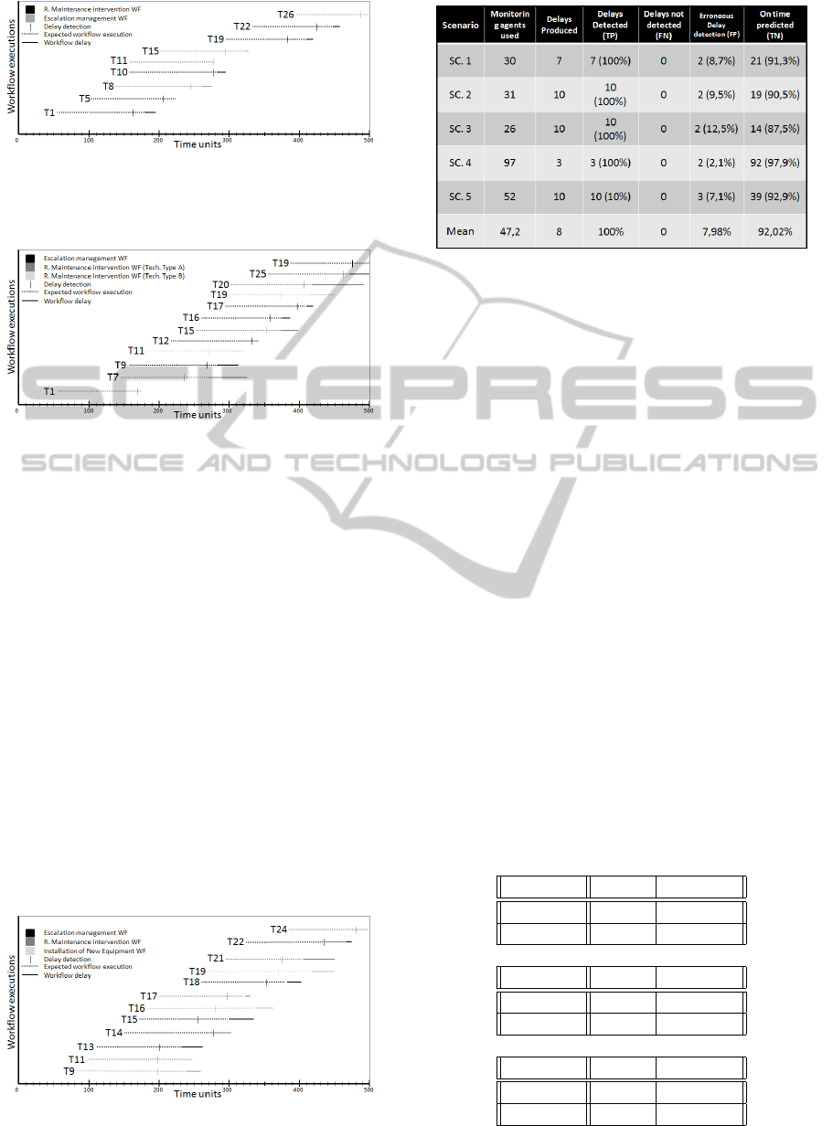
Figure 8: Result of the first scenario where the system re-
sources are 4 type A technicians and a 1 technician staff
leader.
Figure 9: Result of the second scenario where the system
resources are 3 type A technicians, 1 type B technician and
a 1 technician staff leader.
the system is also higher. Ten of this marked work-
flows have been correctly classified as they have suf-
fered a delay, while T14, despite the delay prediction,
ended on time. The workflow defined by the T24 to-
ken has been classified as susceptible of suffering a
delay, however the simulation ended before the work-
flow was delayed. Regarding the kind of workflows
marked as delayed, 3 correspond to the IINE WF, 4 to
the RMI WF and 5 to the EM WF.
5.3 Discussion
The obtained results in the different scenarios show
that our prototype can provide an early detection of
workflow delays. In some cases such as token 19(sce-
nario1), token 7(scenario2) or token 22(scenario3) the
detection is done up to 40 time units before the work-
Figure 10: Result of the third scenario where the system
IINE is added to the workflow environment.
Figure 11: Summary of the different scenarios executions.
flow deadline (32% of the workflow duration). This
delay anticipation could be enough to restructure the
scheduling of the workflow, especially in long dura-
tion workflows as medical device maintenance opera-
tions (which can have long term deadlines) or manu-
facturing processes (with midterm deadlines).
By comparing the first two presented scenarios we
can notice that in the second one there is a higher
number of delays. This fact is due to the lower num-
ber of available resources in the system. As more
workflows are waiting for a resource to be released,
more workflows may be delayed. The higher resource
variety in the second scenario caused the ending of
some workflows that were instantiated after others.
Despite this two remarkable differences, the delay
prediction presented a similar behavior in both scenar-
ios. The third scenario presents similar results to the
second one. We can see how the coexistence of differ-
ent types of WF and resources, as happened before,
causes the ending of some workflows before older
workflows have finished. It is important to notice that
Table 1: Table (a) shows the confusion matrix for the first
experiment results. Table (b) shows the confusion matrix
for the second experiment results. Table (c) shows the con-
fusion matrix for the third experiment results.
PC\RC Delay On Time
Delay 7 2
On Time 0 21
(a)
PC\RC Delay On Time
Delay 10 2
On Time 0 19
(b)
PC\RC Delay On Time
Delay 10 2
On Time 0 14
(c)
PETRI NET BASED AGENTS FOR COORDINATING RESOURCES IN A WORKFLOW MANAGEMENT SYSTEM
521

although the number of delays produced is the same,
the number of erroneous predictions decrease respect
to the second scenario.
Table 1 shows the confusion matrix of the three
experiments presented above and Figure 11 a sum-
mary of the experiments performed. By analyzing the
results we can notice that in any of the performed ex-
periments appear false negatives (delayed workflows
classified as on time workflows). This is an impor-
tant fact as it means that all the delayed workflows
are predicted. Regarding the false positives, we can
see that there are 2 in each experiment. Taking into
account that in each case we are monitoring around
30 workflows, this represents an 8% of the classified
workflows, which is an acceptable percentage. Since
our point of view, in the domain we are dealing with,
a false positive is less harmful than a false negative
as a false positive can result in a workflow checking
by a supervisor while a false negative can produce a
global delay on the system. Although the obtained
results encourage us to follow this research direction,
it is important to remember that the presented results
were obtained from workflow simulations, not from
real procedures. It would be interesting to apply the
presented methodology to real data in order to ana-
lyze its performance in a real environment. It is also
important to remark that the application of our pro-
posed workflow monitoring system is conditioned to
the knowledge of the business resources. Thus, it
seems that could be straight applied inside a company,
but can present difficulties in workflows involving ex-
ternal partners.
6 CONCLUSIONS
This paper has faced two important problems regard-
ing workflow monitoring: how to model workflows
including information about the resources needed to
its execution and how to monitor a workflow for pre-
dicting possible delays in its execution.
For the first issue we presented the resource-aware
Petri nets (RAPN), a Petri net extension based on
workflow nets. RAPN are based in color dense-time
Petri nets, which have been widely used to model
workflows. Its main contribution is the addition of
the resource concept, which is allocated when a con-
crete transition is fired and it is released when the last
transition which needs the resource is fired.
Once the business processes are modeled, work-
flow management systems (WMS) are in charge for
its monitoring. In this paper we proposed an agent-
based workflow management system which monitors
both the business process and the resource of the or-
ganization. Monitoring agents use RAPN to monitor
the workflows in a task level so possible delays in the
execution can be detected and predicted. When pos-
sible delays in the workflow executions are detected,
a reasoning agent analyzes the information providing
from the the different monitoring agents and diagnose
the causes of the delays. This enacts the use of pre-
ventive actions such as prioritizing some executions
or restructuring the workflow in order to avoid or min-
imize this delays.
To test our approach, we simulated a medical
equipment maintenance organization. The simula-
tions we ran fulfilled our expectations, indicating that
an anticipated delay alarm can be predicted in many
different situations. There were also some cases
(around the 6% of the cases and 20% of the predic-
tions) where the prediction alarm was thrown despite
no delay was finally produced (false positive) while
all the delays where succesfully predicted. In the
tested domain the false negatives have a much higher
cost than the fasle positives as they behave the impos-
sibility of applying a preventive action, in this sense
our approach had an apropriate behavior as any false
negative appeared.
As a future work, the incorporation of historical
data both into the delay prediction process and into
the workflow delay prevention is an important point
to consider. Regarding the coordination of agents, we
should contemplate to use a distributed approach in
the MAS instead of a centralized one.
ACKNOWLEDGEMENTS
This research project has been partially funded by
the Spanish Government and FEDER funds through
the projects labeled TIN2008-04547, DPI2009-07891
and CTQ2008-06865-C02-02, DURSI AGAUR SGR
grant 2009-00523 (AEDS) and BR10/18 Scholar-
ship of the University of Girona granted to Pablo
Gay. The authors thank the representatives of the
contributing enterprises of the EU-Project “AIMES”
(ITEA2-07017), for the constructive subject-specific
collaboration. The project is supported by the Span-
ish Avanza I+D program (support code TSI-020400-
2008-47) within the EU-programme ITEA2.
REFERENCES
Abdulla, P. A., Mahata, P., and Mayr, R. (2006). Dense-
timed petri nets: Checking zenoness, token liveness
and boundedness. CoRR, abs/cs/0611048.
ICAART 2011 - 3rd International Conference on Agents and Artificial Intelligence
522

AIMESproject (2008-2010). Deliverable 1.3: requirements
specification.
Bergmann, R., Fremann, A., Maximini, K., Maximini, R.,
and Sauer, T. (2006). T.: Case-based support for
collaborative business. In Proceedings of the 8th
European Conference on CBR (ECCBR06), Springer
LNCS 4106, pages 519–533.
Blake, B. (2005). Coordinating multiple agents for
workflow-oriented process orchestration. Information
Systems and E-Business Management, 1(4):387–404.
Brogi, A., Popescu, R., Brogi, A., and Popescu, R. (2006).
Bpel2yawl: Translating bpel processes into yawl
workflows.
Eshuis, R. and Dehnert, J. (2003). Reactive petri nets for
workflow modeling. In Application and Theory of
Petri Nets 2003, pages 296–315. Springer.
Frankowiak, M. R., Grosvenor, R. I., and Prickett, P. W.
(2009). Microcontroller-based process monitoring us-
ing petri-nets. EURASIP J. Embedded Syst., 2009:1–
12.
Gay, P., Pla, A., Lopez, B., Melendez, J., and ReginaMu-
nier (2010). Service workfloow monitoring through
complex event processing. In Proceedings of the
15th IEEE International Conference on Emerging
Techonologies and Factory Automation (ETFA), Bil-
bao, Spain.
Kalnins, A. and Vitolins, V. (2006). Use of uml and
model transformations for workflow process defini-
tions. CoRR, abs/cs/0607044.
Lombardi, M. and Milano, M. (2010). Allocation and
scheduling of conditional task graphs. Artificial In-
telligence, 174(7-8):500–529.
Muehlen, M. and Recker, J. (2008). How much language
is enough? theoretical and practical use of the busi-
ness process modeling notation. Advanced Informa-
tion Systems Engineering, pages 465–479.
Murata, T. (2002). Petri nets: Properties, analysis and ap-
plications. Proceedings of the IEEE, 77(4):541–580.
Petri, C. A. (1962). Kommunikation mit Automaten. PhD
thesis, Institut f
¨
ur instrumentelle Mathematik, Bonn.
Pla, A. (2010). Predicting and diagnosing delays in a
workflow environment. Master’s thesis, Universitat
de Girona, Girona, Spain.
Rinderle, S., Reichert, M., and Dadam, P. (2004). Cor-
rectness criteria for dynamic changes in workflow sys-
tems: a survey. Data Knowl. Eng., 50(1):9–34.
Rozinat, A., Wynn, M., der Aalsta, W. V., ter Hofstede, A.,
and Fidge, C. (2009). Workflow simulation for opera-
tional decision support. Data & Knowledge Engineer-
ing, 68(9):834–850.
Van der Aalst, W. (1993). Interval timed coloured petri nets
and their analysis.
Van der Aalst, W. M. P. (1998). The application of Petri nets
to workflow management. The Journal of Circuits,
Systems and Computers, 8(1):21–66.
Van der Aalst, W. M. P. and Pesic, M. (2006). Specify-
ing, discovering, and monitoring service flows mak-
ing web services process-aware. BPM Center Report
BPM-06-09, BPM Center.
Van der Aalst, W. M. P., van Dongen, B. F., Herbst, J.,
Maruster, L., Schimm, G., and Weijters, A. J. M. M.
(2003). Workflow mining: a survey of issues and ap-
proaches. Data Knowl. Eng., 47(2):237–267.
Wang, M. and Wang, H. (2002). Intelligent agent supported
flexible workflow monitoring system. In A. Banks Pid-
duck et al: CAISE 2002, LNCS 2348, pages 787–791.
Zarour, N., Boufaida, M., Seinturier, L., and Estraillier, P.
(2005). Supporting virtual enterprise systems using
agent coordination. Knowledge and Information Sys-
tems, 8:330?349.
Zdenk, M. S., Svdov, M., and Hanzlek, Z. (2001). Matlab
toolbox for petri nets. In 22nd International Confer-
ence ICATPN 2001, pages 32–36.
PETRI NET BASED AGENTS FOR COORDINATING RESOURCES IN A WORKFLOW MANAGEMENT SYSTEM
523
