
Reliable and Optimal Location System
for Monitoring Geolocation Objects
Hamid Mcheick and Abdelali Goundafi
University of Quebec at Chicoutimi, Computer Science Department
555 Boul. de l'Université, Chicoutimi (Quebec), G7H-2B1, Canada
Abstract. Location systems for remote objects (vehicle, person, commodity,
etc.) are increasingly used today by several enterprises. These systems use posi-
tioning devices such as GPS and communication devices to send remote loca-
tion data and monitor these objects. The constraint of GPS is that it does not
provide a precise position at any time. The second constraint is to sending re-
mote location data. Often, the communication devices used for this purpose are
GSM modules that send data on the GSM network. The use of GSM network is
expensive to send data periodically. To overcome these drawbacks, monitoring
prototype is proposed to create a reliable and optimal location system using ra-
dio and GPS technologies.
1 Introduction
Location systems are becoming increasingly sought today to ensure the location of
distant objects [1], to facilitate the management of personal, and their products, in-
crease the productivity, etc. these systems are known as AVL (for vehicle location)
and generally the RTLS (for real-time location of several objects). These systems can
be divided into two approaches: i) positioning approach by satellites, such as GPS,
and ii) positioning approach by WSN (Wireless Sensor Networks) that use networks
of wireless sensors. This second approach is divided into two categories: Coarse-
grained [2] is based on Radio Frequency Identification) RFID and Fine-Grained [2, 3]
is based on (Radio Signal Strength) RSS technique. Triangulation using three anten-
nas or at least three satellites, provides a point of geographical position. The method
is called APIT (Approximate Point In Triangle) [4]. Unlike WSN, GPS does not re-
quire complex and costly ground infrastructure to find its position. It is based on an
existing satellite network and open to the public, to triangulate its position [5].
A GPS device cannot transmit remote data, since it can only read signals from
GPS satellites to interpret. Some GPS devices use a GSM-GPRS embedded module to
send the location data. Sending data via the GSM network is reliable given the wide
coverage of the global network. Because it is a private network, data sent are charged.
The accuracy of GPS positioning can be improved by a correction signal from WAAS
satellites reaching WAAS (Wide Augmentation Area System) [6]. This signal is not
always received and still depends on the sensitivity of the GPS antenna and weather.
A-GPS is an alternative pay in case of non availability of WAAS data correction. It
allows contact of ground stations that provide data correction similar to WAAS via a
Mcheick H. and Goundafi A..
Reliable and Optimal Location System for Monitoring Geolocation Objects .
DOI: 10.5220/0003197900770084
In Proceedings of the 1st International Living Usability Lab Workshop on AAL Latest Solutions, Trends and Applications (AAL-2011), pages 77-84
ISBN: 978-989-8425-39-3
Copyright
c
2011 SCITEPRESS (Science and Technology Publications, Lda.)

GSM-GPRS. However, the use of communication via GPRS is expensive. The pro-
posed system must meet the following points: i) How can we improve the positions
identified by the GPS at a lower cost, ii) How to centralize data from multiple tracea-
ble mobiles objects to create a overview of the system and facilitate its management?
Section 2 contains a short description of technologies and systems used in this re-
search. In section 3, we bring the elements of our prototype for an optimal system in
terms of cost and location accuracy and availability. We give in section 4 an overview
of program implementation via a pseudo-code supported with comments. Conclusion
and future research will be given at the end of this article.
2 Background
2.1 Global Positioning System (GPS)
GPS (Global Positioning System) is a navigation system that has overall mission in
comprehensive coverage of the earth. Through a constellation with between 24 and 32
satellites, it can provide information to GPS receivers on their position, speed and
time of acquisition of such information [5]. The GPS alone cannot achieve optimum
accuracy (less than 5m) if weather conditions weaken the signal, or obstacles in urban
obstruct the view of satellites and cause multiple reflections of waves [13]. In these
cases, GPS needs assistance through WAAS or A-GPS to correct its position and
properly handle the signal location.
A. WAAS. As with DGPS, WAAS is a differential technique and consists of three
geostationary satellites and 25 ground stations (WRS: Wide area Reference Stations).
It has the ability to bring precision to three meters or less, in horizontal and vertical
[6][8]. The stations collect data on the constellation of GPS satellites and send this
information to two master stations (WMS Wide area Master Station, located on the
west and east sides). GPS compatible with WAAS can make the needed corrections
for a clearer. If the accurate information on data integrity is below the threshold tole-
rated, DGPS is disabled so that the signal is treated just with Pure GPS signal with a
greater precision margin of errors.
A. Assisted GPS (A-GPS). Unlike GPS, which requires a receiver and an antenna,
the A-GPS works in conjunction with a server hosted by A-GPS operator [7]. The
mobile terminal, equipped with a miniaturized GPS receiver, sends a request to the
server through the IP network. The latter, which knows in real time positioning satel-
lites, and serves as dispatcher tells the terminal to monitor the GPS signals. With this
method, the receiver A-GPS mobile terminal can, unlike traditional GPS receivers,
detect signals of very low amplitude [9]. The A-GPS servers can provide correction
data that can bring accuracy on some GPS to a few tens of centimeters [10] [9]. Often
A-GPS data is sent via the cellular network.
2.2 Radio Communication
The radio transmission was initially implemented to provide point to point communi-
cation over long distances (microwave, satellite connections geostationary) between
78

the fixed networks. The mobility principle was introduced to overcome the problem
of non-visibility of the radio mobile equipments by the base station transmitter. The
waves will no longer be spreading in visibility only but we take into account the ref-
lective waves on all types of obstacles (buildings, roofs, trees, etc.). In an urban envi-
ronment, communication via radio waves is carried by radio signals that are reflected
to all buildings along several directions (multipath). The most used waves belong to
the UHF frequency band (300MHz-3GHz) to provide mobile communications in
urban areas such as wave allows multi-path, crossing barriers with a loss of signal
tolerable, depending on the material through (loss: 4dB Wood, Concrete 10dB). There
are several types of antennas, those that interest us in this quest are omnidirectional
antennas (transmitting in all directions) of type: Whip found in cell phones and allows
a gain of 2 dBi, the antenna length is 6.35 to 12.7 cm, an optimum length for integra-
tion into small mobile devices carried out COS by people; The collinear antennas, like
the Whip are also omnidirectional but allow a higher gain (10dBi-4). Because of the
principle of stacking, these antennas are larger than the Whip and will be more suita-
ble for vehicles.
3 Location System Monitoring Prototype
3.1 Model Description
The RFID or wave radio location systems and radio, can not compete with the accura-
cy of GPS. Our solution is to use GPS to identify object location without going
through the GSM network to provide location data. The system may use GPS mod-
ules that enable to read the correction data (e.g. RINEX). The correction data will be
downloaded via a server connected to a station correction land through an internet
connection. An antenna will be used via a radio modem connected to our server and
be able to broadcast the correction data over a dozen kilometers (the chosen modem
can achieve a transmission radius of 50 km in open field). The geo-locatable objects
are classified into two categories:
The portable devices: cell phones, portable GPS and other portable devices includ-
ing a small GPS. Given the small size of these devices and to keep the portability
aspect, we must couple these devices with small modems RADIO. The disadvantage
of the size results in a low radio range (800m to 2km). The large objects: such as
vehicles, the old merchandise, etc. These objects give us more leeway for the use of
big modem and antennas. On a vehicle, we can install a big radio modem and high-
sensitivity antenna on the hood. The scope becomes larger and may reach, as in the
case of the antenna connected to our server, several tens of kilometers.
The smallest detectable objects are often far from the antenna of our server. To
overcome this problem, we propose a model program to allow portable devices to
relay messages to our radio antenna. This later is connected to the server via the larg-
est objects that have greater range and in the vicinity of our short-range devices.
In the case of short range modem is not the scope from the antenna of the server
for a direct connection or the scope of a runner as explained before; we must ensure
that the data of locations are transmitted by another medium to ensure the real time
aspect. By defining a time or timeout radio transmission, we must switch to GSM-
79
GPRS mode. To summarize, the solution consists of three modules: GPS, radio and
GSM/GPRS for handheld devices. The first handheld devices to send the details via
the radio module to our server if direct connection is not possible, they ask the long
range radio modules nearby to relay information to the server. When the second me-
thod fails shipments. The GSM / GPRS module is requested to send location data to
the server. Vehicles can also work together if their scope is not enough signals for
sending data. In the downlink, the server broadcasts the data to correct position with-
out using long range antenna which is capable of covering a large urban area.
3.2 System Network Topology
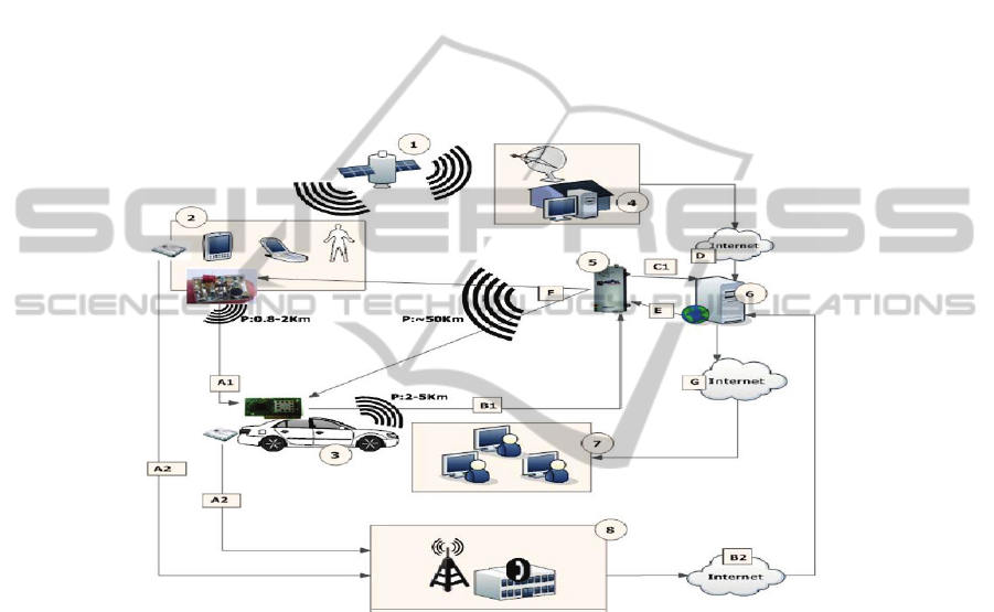
Figure 1 illustrates the network topology of our system.
Fig. 1. Network Topology of our system to communicate Radio and GPRS.
This topology is described by the following steps: i) The GPS satellite sends the
signal to three components 2, 3 and 4, which calculate respectively their positions by
analyzing the GPS signal. ii) Set of portable devices that can communicate in radio
mode A1 to send their positions to our server 6. In case where the radio fails, the
system switches to GSM-GPRS data items A2 that sends data via the Internet (B2) to
our server 6. iii) The vehicles are equipped with larger Radio Modems with a broader,
enabling them to relay location data of Group 2 in B1. Cars can also be equipped with
GSM/GPRS module and further to use as portable devices for two (2). iv) A-GPS
station which calculates the positioning error of GPS in its area. These data are down-
loaded from our server via an Internet connection D. The GPS correction data is
broadcast in F over a wide area via a modem long-range 5. v) Radio Modem Long
Range up to 50 km. It receives location data from our server with a serial connection
(USB, RS232, etc.) via E, transforms the data into radio packets and broadcasts to our
80

remote location equipment in 2 and 3 via radio waves F. A set of users who have
access rights to our server 6.
4 Implementation
This section briefly describes in pseudo code the implementation of the communica-
tion program (Figure 2). Subsequently, we illustrate the communication with the GPS
on a COM port. Finally, some screenshots are presented.
4.1 Pseudo Code Communication Program
Function send_serv(msg, Id)
Start function
If connexion_serveur_radio.open(port)==true do
/* We have the parameters as location message to be transmitted, a random
verification key generated by RAND and the Id_serv which is the ID of our server
for a shipment sent (Id_serv) */
Send_radio( message_localisation, cle_aleat, Id_serv)
/* connexion_serveur_radio with "port" which is our local radio port parameter
is a function that opens a connection via the radio port. if the connection is estab-
lished, it returns true, otherwise returns false.*/
Timer1=5000; // put the variable to 5 seconds
/* Check_Ack function that turns timer1 awaiting acquittal. the server when it
receives our message, pay our random key, and ack cle_aleat are compared, if they
are equal, then the payment is positive and we conclude that the transmission is
complete. The function returns true if matching and false otherwise */
If Check_Ack(cle_aleat, ack, timer1) == true do
connexion_serveur_radio.close(port)
// closure of the radio connection
elseif
/* when you do not receive acknowledgment from the server to the end of
timer1, there is a new invocation send_serv (msg, Id) and the current is stopped
with a return. */
send_serv(msg, Id)
return
end elseif
End Elseif
…
End function
…
End function
81

4.2 Example of AT Commands to GPRS Modem of a Telephone Nokia
These commands are given in Appendix at the end of this article. To send a message
we can use one of two modes:
i) Mode Text[12]:
AT+CMGW="+85291234567"
>AsimpledemoofSMStextmessaging.
ii) Mode PDU:
AT+CMGS=23 //Send message, 23 octets (excluding the two initial ze-
ros) >0011000B916407281553F80000AA0AE8329BFD4697D9EC37
4.3 Communication with GPS on a Port COM
Below the main functions of Java code for communication with devices via a serial
COM port (see more detailed code attached):
// we import the classes javax.comm that manage the communication
// we create our class to open the communications port you want
public class OuvrePort {
/** This is our read buffer from a specific port that we define later in this code */
protected BufferedReader is;
/** Here we define the variable that contains the message to send to our system */
protected PrintStream os;
/** Here, we create an ID of the port */
CommPortIdentifier PortId;
...
/* Here, we chose COM1 port */
portId=CommPortIdentifier.getPortIdentifier("COM1");
...
SerialPort port;//create a serial port
/* Open our port with the message GPS_Appli and a time-
out of 30s */
port=(SerialPort)portId.open("GPS_Appli",
TIMEOUTSECONDS);
...
/* we send our command by writing on the port via println */
os.println(msg);
...
4.4 Running the Tool for Reading the GPS Position (Screenshots)
The tool (program) scans the available communication ports and put them in a drop-
down menu. In our case, COM5 is the GPS port.
After logging on COM5, our application communicates with the GPS using Trim-
ble TAIP protocol. The information is read and sent directly to the server via the In-
ternet in this case.
82
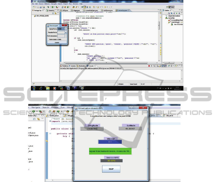
Fig. 2. Running the programme to read the position on the GPS.
Fig. 3. Locating mobile objects in real time via a USB port.
5 Conclusions
The GPS satellite network offers the opportunity to provide the location without addi-
tional hardware with a reasonable accuracy in the range 5-10 meters which can be
enhanced with WAAS or A-GPS. The WAAS system is not available all the time; we
have proposed a network model where a long range antenna will broadcast the correc-
tion signal over a wide area (up to 50KM). Our prototype allows you to benefit from
the increased accuracy of GPS improved by A-GPS. The data download can be done
without cost, via radio communications, to our server. The system supports mobility,
accuracy and implementation with a lower cost since it uses radio waves to communi-
cate data without recourse to a complex communication infrastructure. For future
83
research, we suggest the use of an encryption algorithm for secure radio data. The
algorithm must be light enough not to take a fairly limited bandwidth with the radio
systems.
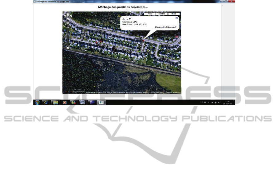
Fig. 4. Web Page generated via Google Map.
References
1. Muhammad Ali Assad, A Real-time Laboratory Testbed For Evaluating Localization Per-
formance of Wifi Technologies. Faculty of Worcester Polytechnic Institute, Electrical and
Computer Engineering, 2007.
2. P. Wilson, D. Prashanth, and H. Aghajan. Utlizing RFID signaling scheme for localization
of stationary objects and speed estimation of mobile objects. In IEEE International Confe-
rence on RFID, 2007.
3. U. Bischoff, M. Strohbach, M. Hazas, and G. Kortuem. Constraint-based distance estima-
tion in ad-hoc wireless sensor networks. In EWSN, 2006.
4. T. He, C. Huang, B. M. Bium, J. A. Stankovic, and T. Abdelzaher. Range-free localization
schemes for large scale sensor networks. In ACM MobiCom’03, 2003.
5. GPS, Global Positioning System, http://www.gps.gov/, 2010.
6. WAAS, Federal Aviation: Administration , www.faa.gov, 2010.
7. SAGEM, A-GPS: The world's first Assited GPS SIM card, www.sagem-orga.com, 2010.
8. CDGPS, The real-time Canada wide DGPS service, http://www.cdgps.com/
e/desc.htm, 2010.
9. A-GPS, Assisted GPS, A-GPS: an overview, information or turorial about the basics of
Assisted GPS (Global Positioning System) or A-GPS used to provide location based servic-
es used for cellular technology and cellular networks, http://www.radio-
electronics.com/info/cellulartelecomms/location_services/assisted_gps.php, 2010.
10. GPSBase, GPS Base station for post-treatment, www.gsf.qc.ca, 2010.
11. Nokia, Activexpert: NOKIA GSM AT command set, http://www.activexperts.com/
activcomport/at/nokia/, 2010.
12. DevHome, Developpers home: How to send SMS message from a computer,
http://www.developershome.com/sms/howToSendSMSFromPC.asp, 2010.
13. Trimble, GPS tutorial, www.trimble.com, 2010.
84
