
PULSE-TYPE NEURO DEVICES WITH TWO TIME WINDOWS
IN STDP AND ITS APPLICATION TO THE MEMORY OF
TEMPORAL SEQUENCES PATTERNS
Katsutoshi Saeki, Shingo Watanabe
College of Science and Technology, Nihon University, Funabashi-shi, Chiba, Japan
Toshiharu Morita, Yoshifumi Sekine
College of Science and Technology, Nihon University, Funabashi-shi, Chiba, Japan
Keywords: Neural Network, Pulse-Type, STDP, Synaptic Weight, Neuro Device, Memory.
Abstract: Since neural networks have superior information processing functions, many investigators have attemptted
to model biological neurons and neural networks. A number of recent studies of neural networks have been
conducted with the purpose of applying engineering to the brain. Especially, neuro devices have been
created that focus on how learning is achieved. Here, we focus on spike timing dependent synaptic
plasticity (STDP) and construct pulse-type neuro devices with STDP. In this paper, we focus on two time
windows in STDP, and we propose a synaptic weight generation circuit which indicates an asymmetric or a
symmetric time window by changing voltages in the proposed circuit. As a result, we show that a pulse-
type neuro device with two time windows in STDP stores temporal sequence output voltage patterns which
conform to the temporal sequence input current patterns for memory.
1 INTRODUCTION
The classical Hebbian learning rule (Hebb 1949) is
believed to play an important role in synaptic
plasticity of neural networks in the brain. This rule
uses mean spike firing correlations between pre- and
postsynaptic neurons to drive learning. Recently, the
form of synaptic plasticity dependent on the order
and time interval of pre- and postsynaptic spikes
(STDP: spike timing dependent synaptic plasticity
(Bi and Poo, 1998) was observed in the hippocampus
and cerebral cortex (Patrick and Curtis, 2002, Sakai
and Yoshizawa, 2003). In general, STDP manifests
itself as a potentiation of a synapse if the presynaptic
spike precedes the postsynaptic spike, and as a
depression if the presynaptic spike follows the
postsynaptic spike (an asymmetric time window). In
addition, it has been reported that the depression
caused when the presynaptic spike precedes the
postsynaptic spike (a symmetric time window)
depends on the influence of an inhibitory neuron
(Tsukada, Aihara, Kobayashi and Shimazaki, 2005).
Furthermore, it has been reported that recall of two
states (autoassociative and heteroassociative) using
the two time windows in the mathematical model
(Samura, Hattori and Ishizaki, 2008) exist.
On the other hand, hardware neuron models with
STDP have been proposed based on the results of
physiological experiments (Tanaka, Morie and
Aihara, 2009 - Schemmel, Grubl, Meier and Mueller,
2006). Especially, the latest research has the purpose
of being applied to engineering. For example, using
analog circuits, associative memory(Tanaka, Morie
and Aihara, 2009), vision model(Zhijun, Murray,
Worgotter, Cameron and Boonsobhak, 2006),
adaptive neuromorphic olfaction chip(Koickal,
Hamilton, Tan, Covington, Gardner and Pearce,
2007), effect of process mismatch(Cameron, Murray
and Boonsobhak, 2007) and floating gate learning
array with STDP(Pankaala, Laiho and Hasler, 2009)
is suggested. Or again, using digital circuits,
navigation robot(Arena, Fortuna, Frasca, Patane and
Sala, 2007) and auditory system based on
FPGA(Cassidy, Denham, Kanold and Andreou,
2007) is shown. Furthermore, mixed signal circuits
with STDP (Schemmel, Grubl, Meier and Mueller,
2006) are proposed. However, these models require
426
Saeki K., Watanabe S., Morita T. and Sekine Y..
PULSE-TYPE NEURO DEVICES WITH TWO TIME WINDOWS IN STDP AND ITS APPLICATION TO THE MEMORY OF TEMPORAL SEQUENCES
PATTERNS.
DOI: 10.5220/0003288004260431
In Proceedings of the International Conference on Biomedical Electronics and Devices (BIODEVICES-2011), pages 426-431
ISBN: 978-989-8425-37-9
Copyright
c
2011 SCITEPRESS (Science and Technology Publications, Lda.)
either complex cell body circuits or large scale
circuits. Moreover, most of circuits use only one time
window in STDP, or use several circuits with two
time windows in STDP, respectively.
We previously proposed a simple cell body
circuit of a pulse-type hardware neuron model (P-
HNM) using CMOS that approximately simulates
pulse signals as the means of information
transmission in the brain (Sekine, Sumiyama, Saeki
and Aihara, 2001, Saeki, Sekine, and Aihara, 1999).
And so, we proposed an asymmetric type of STDP
hardware model. Moreover, we studied the
robustness of this circuit. As a result, we showed that
it was able to make IC implementation (Saeki,
Hayashi and Sekine, 2006, Saeki, Hayashi and
Sekine, 2008, Shimizu, Saeki and Sekine, 2009)
In this paper, we use simple cell body pulse-type
neuro devices, and we propose a synaptic weight
generation circuit with two time windows in STDP.
As to its application, we study the storage of
temporal sequence patterns.
2 PULSE-TYPE NEURO DEVICES
WITH STDP
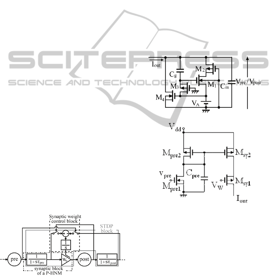
An STDP block diagram is shown in Fig. 1. This
block diagram has cell body blocks and an STDP
block. When pulses are inputted to each temporal
summation block, output pulses from each temporal
summation block have first-order delays and are
transmitted to the subsequent blocks. When the post-
synaptic cell generates the pulses, the synaptic
weight W
p
between pre- and post-synaptic cells is
reinforced based on the output amplitude of the
temporal summation block with the pre-synaptic
cell. On the other hand, when the pre-synaptic cell
generates the pulses, W
p
is suppressed based on the
output amplitude of the temporal summation block
with the post-synaptic cell.
Figure 1: STDP block diagram.
2.1 Circuits of Pulse-Type Neuro
Devices
A pulse-type neuro device is shown in Fig. 2. The
pulse-type neuro device consists of a cell body
circuit and a synaptic circuit. Figure (a) shows the
cell body circuit. When I
out
is inputted to the cell
body circuit, output pulses are generated. This
circuit has a threshold and a refractory period
characteristic. Figure (b) shows the synaptic circuit.
When pulses are inputted to the input terminal V
pre
of the synaptic circuit from the pre-synaptic cell, I
out
is generated. The current I
out
changes according to
V
w
. Therefore, the synaptic weight between the pre-
and post-synaptic cells can be controlled by V
w
.
Spatial summation circuits can also be constructed
when a series circuit of M
sy1
and M
sy2
is connected
in parallel.
(a) Cell body circuit
(b) Synaptic circuit
Figure 2: Pulse-type neuro device.
2.2 Synaptic Weight Generation
Circuit
It is reported that the two time windows in STDP
depends on the influence of an inhibitory neuron
(Tsukada, Aihara, Kobayashi and Shimazaki, 2005).
Focusing on this biological report, we investigated
the synaptic weight generation circuit that is able to
change two time windows by changing voltages.
Figure 3 shows the details of the synaptic weight
control block in Fig. 1. This circuit consists in part
PULSE-TYPE NEURO DEVICES WITH TWO TIME WINDOWS IN STDP AND ITS APPLICATION TO THE
MEMORY OF TEMPORAL SEQUENCES PATTERNS
427
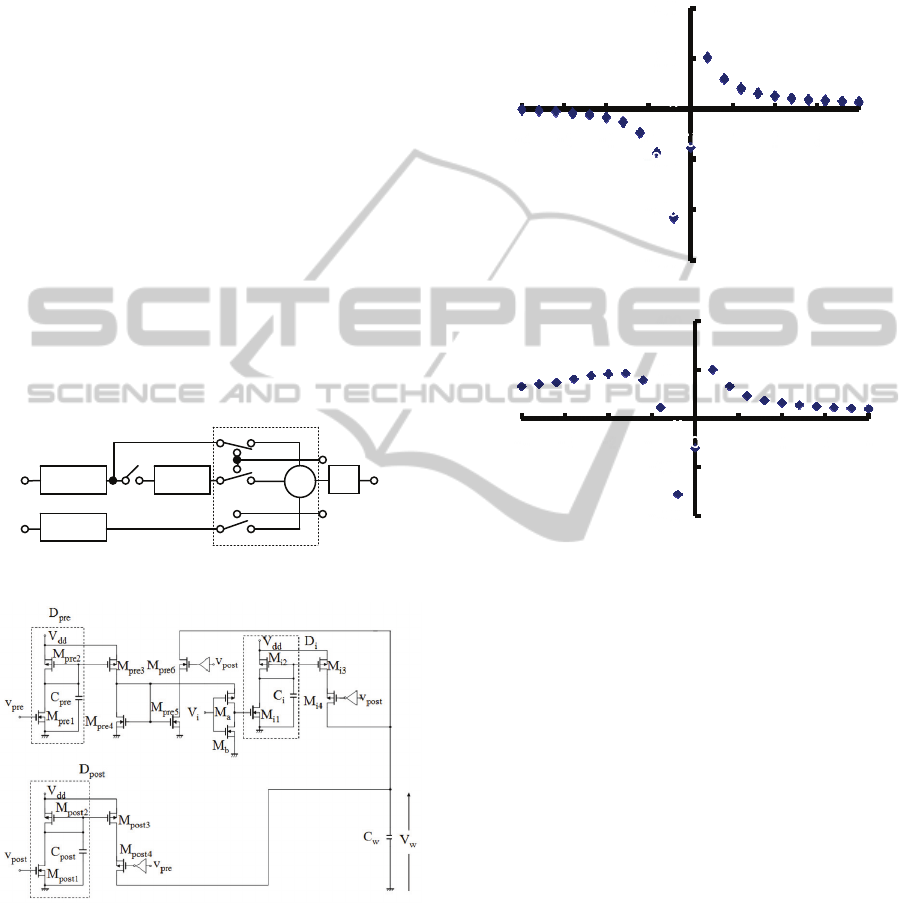
of five blocks; three temporal summation blocks
(D
pre
, D
post
and D
i
) including first-order-delay
elements, a sampling block and an integral block.
Switch S
1
is assumed depending on stimuli of
inhibitory neuron. v
pre
and v
post
display output
voltages of pre-synaptic cell and post-synaptic cell,
respectively. The voltage V
w
is the output voltage of
this circuit and is the parameter that controls the
synaptic weight between the pre- and post-synaptic
cells.
The synaptic weight generation circuit is shown
in Fig. 4. This proposed circuit shows that the two
time windows depend on the V
i
. C
w
represents the
integral block. Mpre
6
, Mpost
4
and M
i4
are sampling
blocks. D
pre
, D
post
and D
i
have first-order delay
elements. Furthermore, M
pre2
to M
pre3
, M
pre4
to M
pre5
,
M
post2
to M
post3
, M
i2
to M
i3
are constructed by current
mirror connection. V
i
is inputted to the input
terminal of the MOS switch consist of M
a
and M
b
. If
V
i
is threshold voltage or over, D
i
is not used. On the
other hand, if V
i
is threshold voltage or under, D
i
is
used. That is to say, it is able to control first-order-
delay elements.
Figure 3: Syanptic weight control block.
Figure 4: Synaptic weight generation circuit.
A function of V
w
in the synaptic weight
generation circuit is shown in Fig. 5. The horizontal
axis is the time interval Δt, which is the time of the
pre-synaptic pulse minus the time of the post-
synaptic pulse, and the vertical axis is the amount of
voltage change ΔV
w
. Figure (a) displays an
asymmetric time window, when V
i
is 3[V] in
proposed synaptic weight generation circuit. Figure
(b) displays a symmetric time window, when V
i
is
-3[V] in proposed synaptic weight generation circuit.
Therefore, it is shown that two time windows in
STDP are obtained by changing voltage V
i
.
(b) Symmetric time window.
Figure 5: Characteristics of V
w
in the synaptic weight.
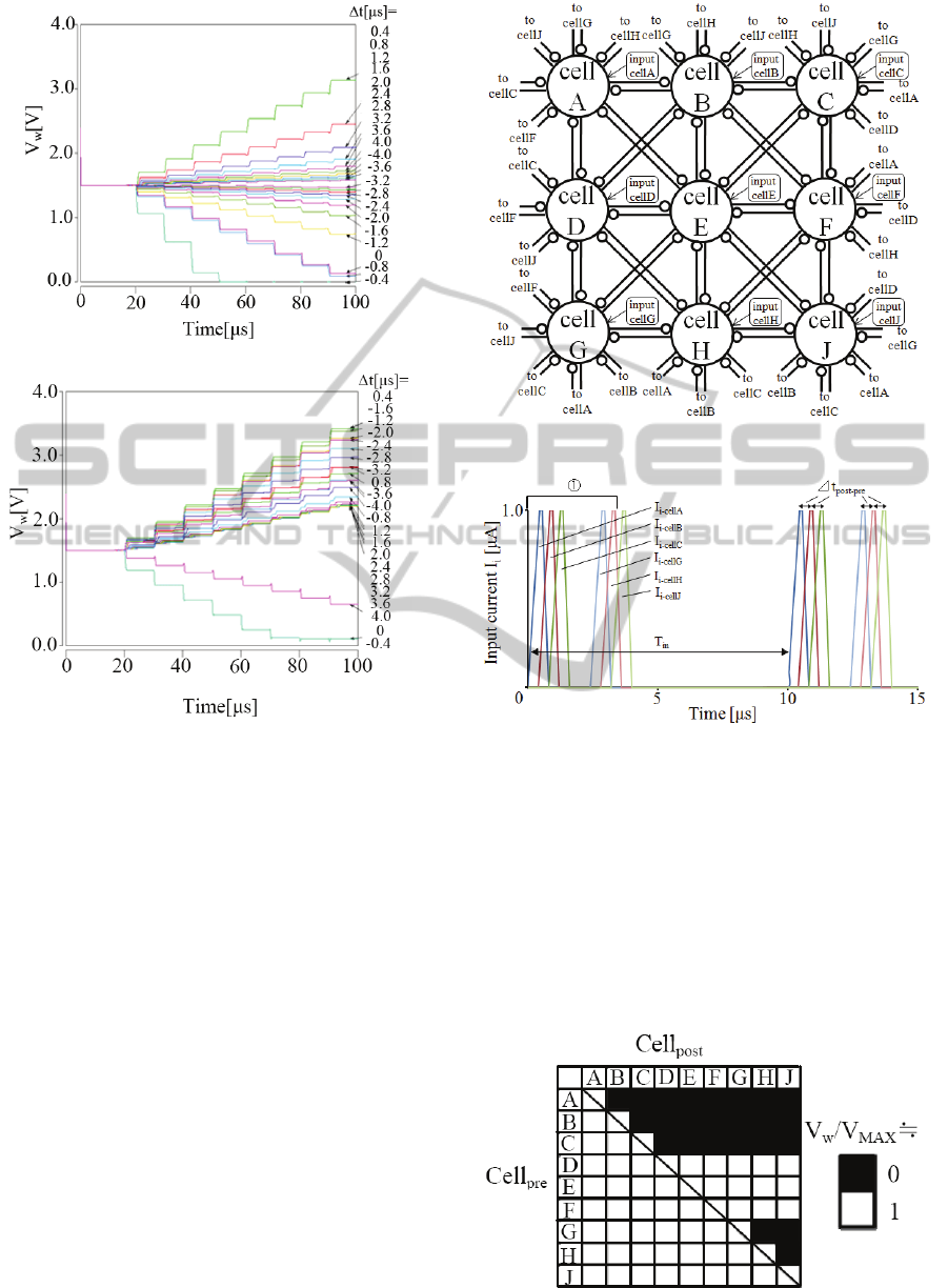
Figure 6 shows the simulation result for the
synaptic weight changes by the STDP function. (a)
and (b) show the asymmetric and the symmetric
time window type, respectively. Δt is the parameter.
3 MEMORY OF TEMPORAL
SEQUENCES PATTERNS
Figure 7 shows a construction of a hardware STDP
model. It shows a Hopfield-type network which is
the interactive connection for all neuron models. In
this figure, cell A ~ J are cell body models, the open
circles indicate STDP synapses. Input cells A ~ J
show the input stimulus current. If we assume that
cell A = cell
pre
and cell B = cell
post
, the synaptic
weight displayed will be W
A, B
(cell A to cell B) and
W
B,A
(cell B to cell A). Furthermore, W
A, B
and W
B, A
are changed depending on the output pulse timing
from cell A and cell B. That is to say, temporal
-4
0
1
2
3 4 -1
-2
-3
200
400
-
200
-400
Δt[μs]
ΔV
w
[
mV
1/s
1/(1+sτ
pre
)
1/(1+sτ
post
)
1/(1+sτ
i
)
S
1
V
W
v
pre
v
post
v
post
v
pre
+
_
D
p
re
D
post
D
i
Sampling block
Integral block
+
-4
0
-1
-2
-3
1 2 3
4
-600
400
200
-400
-200
ΔV
w
[mV]
Δt
[μ
s
]
(a) Asymmetric time window.
BIODEVICES 2011 - International Conference on Biomedical Electronics and Devices
428
(a) Time transition in asymmetric time window.
(b) Time transition in symmetric time window.
Figure 6: Time transition in synaptic weight.
sequence patterns are stored by using synaptic
weight, which is dependent on the differential pulse
timing. In this examination, we use the nine pulse-
type neuro devices with STDP cells A ~ J.
Figure 8 shows an example of the current
patterns of the temporal sequence pulses for ①
which are input to cell
pre
and cell
post
. The horizontal
axis corresponds to time, while the vertical axis
shows the input current for each pulse-type neuro
device. Here, Δt is the interval, which is the time
difference between the post-synaptic and pre-
synaptic pulses, and T
in
is the period of the pulse
current. So, Δt = 0.4 μs and T
in
= 10 μs are used as
an example. Here, there is no input for the pulse
current when we assume that cell D, E, and F have
no input. The current patterns of the temporal
sequence pulses after input are shown as ①.
Figure 9 shows a distribution of synaptic-
weight. The horizontal axis corresponds to the cell
pre
,
while the vertical axis shows the cell
post
. This result
shows when V
i
is 3[V] and -3[V] in the proposed
Figure 7: Construction of hardware STDP model.
Figure 8: Example of current patterns of temporal
sequence pulses.
synaptic weight generation circuit. V
w
/V
MAX
represent output voltage V
w
of the synaptic weight
generation circuit that is normalized with V
MAX
(=
V
dd
). The black squares mean that W
pre,post
is strong
when V
w
/V
MAX
approaches 0.0. On the other hand,
the white squares mean that W
pre,post
is weak when
V
w
/V
MAX
approaches 1.0. That is to say, it is shown
that the synaptic weight changes depending on the
input current patterns of temporal sequence pulses.
Figure 9: Distribution of synaptic-weight.
PULSE-TYPE NEURO DEVICES WITH TWO TIME WINDOWS IN STDP AND ITS APPLICATION TO THE
MEMORY OF TEMPORAL SEQUENCES PATTERNS
429
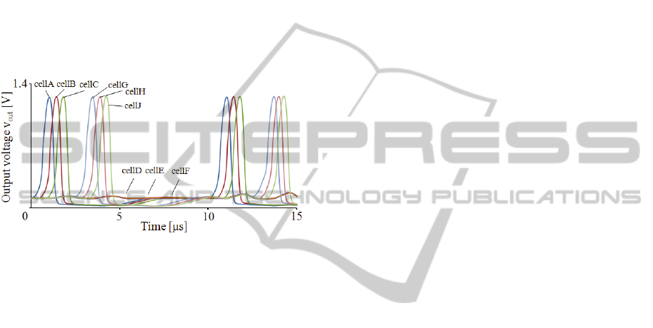
Figure 10 shows an example of the order of the
pulses that the pulse-type neuro device uses at each
cell output. The horizontal axis corresponds to time,
while the vertical axis shows the output voltage of
each pulse-type neuro device. This result shows that
the order of the output pulses that the pulse-type
neuro device with two time windows in STDP uses
for each cell output is dependent on each of the
synaptic weights shown in Fig. 9. This is similar to
the order of the current patterns of the temporal
sequence pulses in ①. Therefore, we showed that
the pulse-type neuro device with STDP stores the
temporal sequence output voltage patterns which
obey the temporal sequence input current patterns.
Figure 10: Output waveforms of pulse-type neuro device
with STDP.
4 CONCLUSIONS
For purpose of constructing brain-type information
processing systems, we constructed neuro devices
with learning functions.
In this paper, we focus on two time windows in
STDP, and we propose a synaptic weight generation
circuit which indicates an asymmetric or a
symmetric time window by changing voltages in the
proposed circuit.
As a result, we show that a pulse-type neuro
device with two time windows in STDP stores
temporal sequence output voltage patterns which
conform to the temporal sequence input current
patterns for memory, because synaptic weight
changes depending on the input current patterns of
temporal sequence pulses. From this result, it is
shown that there is every possibility of constructing
an associative memory device which includes
autoassociative and heteroassociative memory using
the two time windows.
In the future, we will study the recall of two the
states (autoassociative and heteroassociative) of
temporal sequence patterns using a pulse-type neuro
device with two time windows in STDP.
ACKNOWLEDGEMENTS
This work has been supported in part by MEXT
Grant-in-Aid #21560367. Furthermore, this work
has been supported in part by VLSI Design and
Education Center (VDEC), the University of Tokyo
in collaboration with Cadence Design Systems, Inc.
REFERENCES
Hebb, D. O, 1949. “The organization of behavior, A
Neuropsychological Theory”, New York.
Bi G-q., Poo M-m., 1998. “Synaptic modifications in
cultured hippocampal neurons, Dependent on spike
timing, synaptic strength, and postsynaptic Cell Type”,
J. Neurosci.
Patrick D. R., Curtis C. B., 2002. “Spike Timingdependent
synaptic plasticity in biological systems”, Bio.Cybern.
Nishiyama M., Hong K., Mikoshiba K., Poo M-m., &
Kato K., 2000. “Calcium stores regulate the polarity
and input specificity of synaptic modification”,
Nature.
Sakai Y., and Yoshizawa S., 2003. “Mechanisms of
synaptic competition and regulation in spike-time-
dependent synaptic plasticity rules”, IEICE Technical
Report.
Tsukada M., Aihara T., Kobayashi Y., Shimazaki H., 2005.
“Spatial analysis of spike-timing-dependent LTP and
LTD in the CA1 area of hippocampal slices using
optional imaging”, Hippocampus.
Samura T., Hattori M. and Ishizaki S., 2008. “Sequence
disambiguation and pattern completion by
cooperation between autoassociative and
heteroassociative memories of functionally divided
hippocampal CA3”, Neurocomputing.
Tanaka M., Morie T. and Aihara K., 2009. “A CMOS
Spiking Neural Network Circuit with
Symmetric/Asymmetric STDP Function”, IEICE
Trans.
Zhijun A., Murray A., Worgotter F. Cameron K. and
Boonsobhak V., 2006. “A neuromorphic depth-from-
motion vision model with STDP adaptation”, IEEE
Trans. on Neural Networks.
Koickal T., Hamilton A., Tan S., Covington J., Gardner J.
and Pearce T., 2007. “Analog VLSI Circuit
Implementation of an Adaptive Neuromorphic
Olfaction Chip”, IEEE Trnas. on Circuits and Systems
I.
Cameron K., Murray A. and Boonsobhak A., 2007.
“Minimizing the effect of process mismatch in a
neuromorphic system using spike-timing-dependent
adaptation”, IEEE Trans. on Neural Networks.
Pankaala M., Laiho M. and Hasler P., 2009. “Compact
floating-gate learning array with STDP”,
IJCNN2009.
Arena P., Fortuna L., Frasca M., Patane L. and Sala C.,
2007. “Integrating high-level sensor features via
BIODEVICES 2011 - International Conference on Biomedical Electronics and Devices
430

STDP for bio-inspired navigation”, IEEE
ISCAS20007.
Cassidy A., Denham S., Kanold P. and Andreou A., 2007.
“FPGA Based Silicon Spiking Neural Array”,
BIOCAS 2007.
Schemmel J., Grubl A., Meier K. and Mueller E., 2006.
“Implementing Synaptic Plasticity in a VLSI Spiking
Neural Network Model”, IJCNN2006.
Belhadj B., Tomas J., Malot O., N’kaoua G., Bornat Y.
and Renaud S., 2008. “FPGA-based architecture for
real-time syanaptic plasticity computation”,
ICECS2008.
Sekine Y., Sumiyama M., Saeki, K. and Aihara K., 2001.
“ A Λ-Type Neuron Model using Enhancement-Mode
MOSFETs”, IEICE Trans.
Saeki K., Sekine Y. and Aihara K., 1999,“A Study on a
Pulse-type Hardware Neuron Model using CMOS,”
International Symposium on Nonlinear Theory and Its
Applications (NOLTA99).
Saeki K., Hayashi Y. and Sekine Y., 2006. “Extraction of
Phase Information Buried in Fluctuation of a Pulse-
type Hardware Neuron Model Using STDP”, 2006
International Joint Conference on Neural Networks
(IJCNN2006).
Saeki K., Hayashi Y. and Sekine Y., 2007. “ Noise
Tolerance of a Pulse-type Hardware Neural Network
with STDP Synapses - Thermal Noise and Extraction
of Phase Difference Information -”, Proc. IEEJ
International Analog VLSI Workshop.
Saeki K., Hayashi Y. and Sekine Y., 2008. “Pulse-Type
Neuro Devices With Spike Timing Dependent
Synaptic Plasticity”, Bio Devices2008.
Shimizu R., Saeki K. and Sekine Y., 2009. “A Pulse-Type
Hardware Neural Network with STDP for Memory of
Temporal Sequences Patterns”, Proc. IEEJ (C).
PULSE-TYPE NEURO DEVICES WITH TWO TIME WINDOWS IN STDP AND ITS APPLICATION TO THE
MEMORY OF TEMPORAL SEQUENCES PATTERNS
431
