
BUILDING LOCAL K-D TREE FOR FLEXIBLY LABELING
ARTICULATED POINT SETS
Wu Huang and Shihong Xia
Institute of Computing Technology of the Chinese Academy of Science, Graduate University of Chinese Academy of Science
#6 Academy South Road, Beijing, China
Keywords:
Optical motion capture, Label markers, Local k-d tree, Clinical gait analysis.
Abstract:
Optical motion capture system is widely used to acquire human motions by capturing the trajectories of mark-
ers that are attached to the body. Identifying the marker trajectories is challenging but indispensable in most of
real applications. Conventional methods rely on either labor-intensive manually labeling or auto-labeling with
assumption of pose similarity to the topological model. This paper presents a novel method to flexibly label
markers from human motion capture sequences. The point sets in a rigid segment defined in the topological
model are firstly clustered by using the spectral clustering algorithm. For each rigid segment, a local k-d tree
is constructed to robustly match two point sets without pose similarity assumption. To match all rigid bodies
with those in topological model for efficiently and correctly labeling, the labeling process is carefully designed
using the articulated structure of acquired data. Experiments show that our method outperforms conventional
methods in accuracy and is robust when labeling markers in motion capture sequences from different subjects.
1 INTRODUCTION
Marker-based motion capture (MOCAP) system has
become one of the most popular methods for ac-
quiring human motions in clinical gait analysis,
sports training and computer games(Guerra-Filho,
2005)(Gleicher, 1999).It can reconstruct the motions
of moving subjects by measuring the 3D trajectories
of passive reflective markers attached to the subjects.
To use the recorded data, information such as joint an-
gles, skeletal parameters and the topology of the cap-
tured subjects should be extracted. Most commercial
tools (e.g. Vicon(OMG, 2009)) provide an additional
process called labeling to identify each marker based
on the predefined topological model to get the geo-
metric information. Unfortunately, this work is of-
ten accomplished manually which is labor-intensive,
highly non-productive and error prone. Every time a
new subject is to be captured, the manual identifica-
tion is needed.
Generally speaking, different captured subjects
will have different geometric information. Essen-
tially, the labeling work is to generate geometric mod-
els for different captured subjects. Currently, most ap-
proaches assume that the geometric model has been
identified in the first frame of motion sequences as
most commercial tools do. Some approaches provide
a topological model as a point set template and use
the method of Point Pattern Matching (PPM) with ar-
ticulated sparse feature points to generate geometric
models for different captured subjects automatically.
The topological model only contains marker set and
the topology of the captured subjects without specific
geometric information. However, this automatically
labeling process requires the captured subjects to per-
form the same initial pose as the topological model.
In situations such as clinical gait analysis for disabled
people, it is difficult for them to perform special pose.
It is still an open problem to label captured markers
automatically using topological model without the re-
quirement of special initial pose.
This paper describes a new method to automati-
cally label points or generate geometric models in ac-
quired motion data, which only requires that the ac-
quired data has the same spatial distribution of points
in each rigid body and does not need the identical
scale and pose with the topological model. To serve
this purpose, we assume non-interrupted marker tra-
jectories can be obtained. To construct a local k-d tree
for each rigid body (Here, ”local” means that the k-d
tree is built within a local rigid body.), we first clus-
ter these marker into different rigid groups. The la-
beling process is implemented using constructed local
k-d tree articulately to obtain robust labeling results.
288
Huang W. and Xia S..
BUILDING LOCAL K-D TREE FOR FLEXIBLY LABELING ARTICULATED POINT SETS.
DOI: 10.5220/0003299802880294
In Proceedings of the International Conference on Biomedical Electronics and Devices (BIODEVICES-2011), pages 288-294
ISBN: 978-989-8425-37-9
Copyright
c
2011 SCITEPRESS (Science and Technology Publications, Lda.)

Figure 1: Input and output of our approach. Left are 3D
marker trajectories acquired from MOCAP system. Right
are the results of marker labeling that are also the geometric
models.
Fig. 1 shows the input and output of our approach.
2 RELATED WORK
The task of labeling markers or identifying acquired
data based on the topological model can be consid-
ered as the problem of Point Pattern Matching (PPM)
with articulated sparse feature points.
Many researchers have efforts on the area of
PPM(Cox and de Jager, 1992)(Li et al., 2003).
Their work mainly focuses on geometric invariant
or constrained satisfaction in affine transformation.
The methods frequently used include graphics, in-
terpretation trees(Gaede and Gnther, 1998), Haus-
daorff distance(Mount et al., 1999), geometric hash-
ing(Wolfson and Rigoutsos, 1997). The human is
a high-dimensional nonrigid object that can perform
various complicated motion. The geometric invariant
or constrained satisfaction employed in these methods
can not be easily met during human’s performances.
As a result, these approaches can hardly adapted for
the situation of high-dimensional articulated motion.
Baihua Li et al.(Li et al., 2004)(Li et al., 2008)
introduced a segment-based method for PPM and
employed it to solve the problem of labeling mark-
ers. The used topological model is obtained manually
from the same acquired subject at different poses. The
labeling process is carried out within each rigid seg-
ment. Their method can identify acquired data that
is obviously visually different from the topological
model. Unfortunately, the computation cost is high,
and the topological model for different subjects needs
to be re-built manually. Qian Yu et al.(Yu et al., 2007)
proposed a method to label markers for multiple inter-
acting articulated targets. They learnt a motion model
and a structure model for each target from calibration
sequences, and used them to identify markers. Us-
ing learned models, their method can label markers
for different interacting targets. In order to start the
marker tracking, the markers in the first frame of cali-
bration sequences for each target must be correctly la-
beled by hand. In fact, this manually process is estab-
lishing a correspondence from the topological model
to the acquired motion data.
To label different subjects with a generic topolog-
ical model that has similar topology to the acquired
subjects, Baihua Li et al.(Li et al., 2005) designed a
new similarity k-d tree and used this data structure to
identify markers in only one frame. The method can
identify acquired data that have non-identical scales
with the topological model. It can be processed very
fast, but the method requires that the pose of acquired
data and topological model must be similar. Bent-
ley(Bentley, 1975) first introduced the binary k-d tree
in 1975, in which he used axis-orthogonal cutting
hyper-planes through data points to partition recur-
sively a point-set at each interior node into two sub-
sets. Then Bentley(Bentley, 1990) introduced an opti-
mized semi-dynamic k-d tree taking the data distribu-
tion into account, to construct this kind of k-d tree,
one should first find out the dimension of the data
that has the largest spread to determine the orthogonal
hyper-plane axis, and then the mean-partition of data
extension in that dimension is calculated to locate the
hyper-plane.
Other researchers tried to extract the informa-
tion such as skeletal parameters, joint angles and the
topology from marker trajectories without the step
of labeling. Adam G.Kirk et al.(Kirk et al., 2005)
used spectral clustering algorithm(Ng et al., 2001) to
identify rigid bodies from motion capture sequences
and estimated the skeletal parameters. Edilson de
Aguiar et al.(Aguiar et al., 2006) adopted a method
that was very similar to that was proposed by Adam
G.Kirk et al.(Kirk et al., 2005) to automatically ex-
tract the articulated skeletons from 3D marker tra-
jectories. Alexander Hornung et al.(Hornung et al.,
2005) also proposed a method to extracted articulated
skeletons from motion sequences. They introduced a
self-calibrating process to get the topology of the cap-
tured objects. The methods mentioned above can es-
timate skeletal parameters and topology without iden-
tifying each marker which is convenient for computer
animations.
However, to get precise locations of joints in clin-
ical analysis, the experience formulas provided by
biomechanics are always used and the step of label-
ing is always required so these methods can not be
easily applied to our problem. Inspired from their
method of identifying rigid bodies, we also apply the
spectral clustering algorithm(Ng et al., 2001) to get
marker groups representing different rigid bodies and
the details will be given in Section 3.1.
BUILDING LOCAL K-D TREE FOR FLEXIBLY LABELING ARTICULATED POINT SETS
289
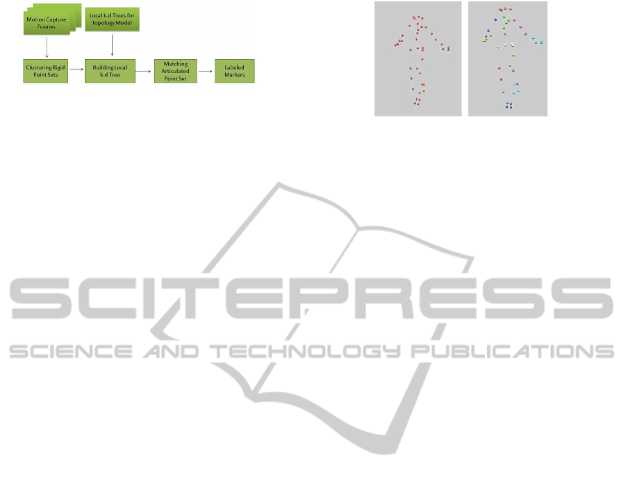
Figure 2: Pipeline overview of our algorithm.
3 OUR APPROACH
The topological model used in our method is an artic-
ulated structure composed of rigid bodies, in which
the neighbor rigid bodies are linked with the shared
markers. In order to label the acquired motion data
with a generic topological model, we use the intrin-
sic rigid segment constraint of 3D marker trajectories
to cluster the markers into rigid body sets. Inspired
by the fact that k-d tree is a state-of-the-art method
for matching point pattern with similar distributions,
we build local k-d tree structure for each marker set
in the topological model and the acquired data. Since
the obtained rigid segment has the property of geo-
metric invariance during affine transformation, so the
proposed method can also label markers in the case of
distinct pose difference.
Given the 3D marker trajectories acquired from
commercial optical MOCAP system, our approach
can give name for each trajectory without manual ef-
fort. There are three steps to accomplish this task.
The first step is to divide markers into different
groups. Each one of them represents a rigid body part.
We call this process Clustering Rigid Point Sets(See
Section 3.1).
Give a list of body segments and their associated
markers, we can build a local k-d tree according to the
topological model for each marker group(See Section
3.2). The topological model has similar topology but
non-identical scales to acquired data and a local k-d
tree is also constructed for each rigid body in the topo-
logical model. Our labeling process is based on these
local k-d trees to build a correspondence between the
topological model to acquired data.
Finally, in order to match each rigid body with
the one in topological model, we make the labeling
process articulately execute for each marker group
based on the topology provided by the topological
model. We call this process matching articulated
point sets(See Section 3.3). Fig. 2 illustrates the
pipeline of our approach.
Figure 3: Rigid body clustering. Left shows the input
points. Right is the result of rigid body clustering. Different
color groups represent different rigid bodies.
3.1 Clustering Rigid Point Sets
In this section, we illustrate our clustering procedure,
which is used to identify individual rigid bodies from
the marker’s 3D trajectories.
In a rigid body, the distance between any two
markers keeps almost constant over time. However
it varies if the markers belong to different parts. To
choose markers of each rigid body, we employ spec-
tral clustering algorithm(Ng et al., 2001) on the stan-
dard deviation of the mutual marker distances over
time. To avoid manually effort we get the affinity ma-
trix A as(Zelnik-manor and Perona, 2004) did:
A
i, j
=
(
exp(−d
2
i, j
/(2δ
i
δ
j
)), i 6= j
0, i = j
(1)
where d
i, j
is the standard deviation of distance be-
tween marker i and j δ
i
= d
k,i
is the K-th neighbor
of marker i in the standard deviation space. In our ex-
periments, we use a single value of K = 5 because the
number of markers in each group is no more than 5
and it gives good results.
We apply spectral clustering algorithm(Ng et al.,
2001) hierarchically to get robust clustering result
based on the topological model. First, the cluster-
ing algorithm will divide the point set into two clus-
ters, C
1
and C
2
, which represent upper and lower part
of human respectively. Then the spectral clustering
is employed again within each cluster to get proper
marker groups that can be used to represent rigid bod-
ies. Fig. 3 demonstrates that our approach can ro-
bustly identify all individual segments of the human
body.
Because the common point shared with two seg-
ments can be clustered into any of the two segments,
compared with the topological model there will be
some segments having one point lost. This lost point
must be added into proper segment while labeling. To
solve this problem we design an articulated point set
matching procedure that will be discussed in detail
later.
BIODEVICES 2011 - International Conference on Biomedical Electronics and Devices
290

3.2 Building Local K-D Tree
In this section, we give introduction on how to build
local k-d trees for the point sets in topological model
and acquired one. As there is no identical scales be-
tween topological model and acquired data, the la-
beling work can not be accomplished by solving the
problem of absolute orientation(Arun et al., 1987) so
we make use of local k-d trees to label markers in dif-
ferent rigid bodies.
The local k-d tree is built for each rigid body,
which is identified by the procedure introduced in
Section 3.1. Since single rigid will hold geometric
invariance during affine transformation, constructing
local k-d tree for each rigid body and labeling their
associated points can be applied to acquired data that
are significantly different from topological model.
As the topological model point set T = {t
i
∈
R
3
}
M
i=1
and the acquired point set O = {o
i
∈ R
3
}
M
i=1
are usually obtained in distinct coordinate systems
and performing different pose, they need to be aligned
to a consistent coordinate system by centering and ro-
tation before constructing local k-d tree. This process
can change two point set with different statues into a
same pose under a consistent coordinate. Firstly, the
centroids of T and Q is estimated as in Equ. 2. Sec-
ond, the orientation vectors can be calculated from the
weighted second distribution moments as Equ. 3 and
Equ. 4 in(Li et al., 2005)
−→
c
T
=
∑
M
i=1
t
i
M
,
−→
c
O
=
∑
M
i=1
o
i
M
(2)
−−→
CO
T
=
1
M
∑
i
(t
i
−
−→
c
T
)|t
i
−
−→
c
T
| (3)
−−→
CO
O
=
1
M
∑
i
(o
i
−
−→
c
O
)|o
i
−
−→
c
O
| (4)
where t
i
∈ T,o
i
∈ O and M is the number of points in
the point set.
Finally, each point in T and O should be trans-
formed with respect to their centroid and the orienta-
tion vectors by suitable translation vector t and rota-
tion matrix R as in Equ. 5.
x
′
y
′
z
′
= R(
x
y
z
+ t) (5)
where x, y,z denotes the original coordinates of each
point in the point set and x
′
,y
′
,z
′
represents the
aligned coordinates.
For the topology model, the rotation matrix R can
be set as identity matrix and the translation vector t is
the negative centroid vector of
−−→
CO
T
. For the acquired
point set, R represents the rotation matrix of rotating
−−→
CO
O
into
−−→
CO
T
and t is also the negative centroid vec-
tor of
−−→
CO
O
. In the former work of (Li et al., 2005), for
the acquired data the R was defined as a rotation ma-
trix only around the z-axis because they assumed that
human objects were standing straight, parallelling to
the vertical z-axis and there are no rotations around
other two axis. To satisfy this assumption, the cap-
tured objects must perform the same pose with topo-
logical model and they can only change their orien-
tations around the z-axis. As we build k-d tree for
each rigid body rather than the whole body, the issue
caused by pose difference can be handled by label-
ing each local rigid segment. Because the rigid bod-
ies can maintain geometric invariance during affine
transformation, we can define rotation matrix R for
acquired data around each axis to align local different
rigid bodies. This operation makes our method can
apply to acquired data, which has visually different
pose with the topological model.
Now, for a given aligned 3-dimension topological
model points set
˜
T = {
˜
t
i
∈ R
3
}, we can build local k-
d tree for it. Firstly, we sort the points respectively
along x-axis, y-axis and z-axis. Then the orthogonal-
axis OA
ϕ
∗
will be determined as Equ. 6.
OA
ϕ
∗
=
1
2
max
ϕ∈{x,y,z}
∆ϕ (6)
where ∆ϕ = max
˜
t
k
i
∈
˜
T
((
˜
t
k+1
)
ϕ
− (
˜
t
k
)
ϕ
|(
˜
t
k
i+1
)
ϕ
≥
(
˜
t
k
i
)
ϕ
),(i = 1, ..., M) is the maximum coordinate
interval in the direction ϕ,and i is a sorting index.
Next, we divide the point set into left subset P
l
and
right one P
r
. The points in the left subset are smaller
than OA
ϕ
∗
in axis ϕ
∗
while the right are bigger. Then
an interior node containing the orthogonal-axis(e.g.
x,y or z) and the number of points n
l
split to the left
tree will be constructed. In the subset P
l
and P
r
, the
procedures of choosing orthogonal-axis and splitting
point set based on the axis will be implemented recur-
sively until they contain only one point. Then a leaf
node storing this point is built.
Finally, for the aligned acquired points set, we use
the informationstoring in each interior node of its cor-
responding local k-d tree in the topological model to
construct the acquired one. Starting from the root
node, we first split the aligned acquired point set
based on the hyper-plane orthogonal-axis contained
in its corresponding local k-d tree’s root node in the
topological model. Then the n
l
smallest points along
this axis in the acquired point set are stored in the left
child node, and the rest are stored in the right child
node. In this way, the acquired point set will be split
into two parts at each interior node. In each subset,
this split procedure will be implemented recursively
BUILDING LOCAL K-D TREE FOR FLEXIBLY LABELING ARTICULATED POINT SETS
291

until the leaf node contains only one point. Up to now,
we have built a local k-d tree for acquired point set
that has the same structure with its topological model.
3.3 Matching Articulated Point Sets
Having built local k-d tree for each rigid body of ac-
quired data, the left-right traversal of the successive
leaf nodes in the two trees for point set in topologi-
cal model and acquired one serves to define the cor-
responding point-pair match. The label of each topo-
logical model point is assigned to its matching point
in the acquired data.
However, before labeling and building the trees,
there still exists a problem to be solved. Although
we have divided points into different groups and each
one of them represents the rigid body of human, we
still cannot tell the difference between these groups.
For example, which group represents the points at-
tached to the waist? Which one corresponds with
head? More importantly, the segments in the left
part and the right part can not be distinguished and
this left-right ambiguity will result in wrongly labeled
segments. A direct method maybe enumerating each
rigid body and found the right one. Employing this
violent method, the computation cost could be rather
high and the difference between left and right part
of acquired objects can not be told. Also the lost
point mentioned in Section 3.1 must be added into the
proper segment. To solve this problem, we make the
process of labeling carry out articulately based on the
topology provided by the topological model.
We begin to label markers from groups that are
classified as the lower part of human body. On gen-
eral, the points attached to the waist can be consid-
ered belong to either lower part or upper part, but
the experiments carried out by us suggest that if the
captured object exercises his joint in each degree of
freedom the points on the waist can be divided into
upper part. Then we can find out one of the group
within the upper part that has minimal standard devi-
ation between the points pertained to the lower part
and consider them as waist. Then we can build a local
k-d tree for this rigid using the method mentioned in
Section 3.2 and labeling its associated points by the
left-right traversal of the successive leaf nodes in this
local k-d tree and its corresponding one in topological
model.
As the waist rigid has some common points with
other groups, we can use these points combined with
spectral clustering algorithm(Ng et al., 2001) to label
other groups. Here we take the left thigh as an exam-
ple. As shown in Fig. 4, left thigh rigid and waist rigid
share the same point named ”LFWT”. This point will
Figure 4: Example of same points. The blue ellipse rep-
resents the left thigh rigid and the green one is the waist.
The point that is surrounded by a red ellipse is the common
point named ”LFWT”.
be clustered into the rigid of waist because its stan-
dard deviations between other points attached to waist
rigid are closer to zero than the ones belonged to left
thigh rigid, which is the example of lost point men-
tioned in Section 3.1. After labeling the waist group
we can identify which point being ”LFWT”. Then we
add this point into the lower part group and use spec-
tral clustering algorithm(Ng et al., 2001) to identify
individual rigid bodies of the lower part. It is easy to
infer that the group containing point ”LFWT” is the
left thigh rigid and the matching process can be ex-
ecuted. Next, the points in the left calf rigid can be
labeled in the same way. This procedure will be car-
ried out articulately until all the points in each rigid
body have been labeled.
4 EXPERIMENTAL RESULTS
We tested our algorithm on motion capture sequences
from the CMU motion capture database(CMU, 2009),
in which 3D marker trajectories were acquired via Vi-
con system(OMG, 2009). The motion sequences we
used for testing are comprised of 200-1500 frames
and performing, for example, walking, simply exer-
cising his joints, jumping. The frame rate is of 120
frames/sec. Each marker has a non-interrupted trajec-
tory during the whole motion. The topological model
used in our experiments is taken from a subject that
have different scale and pose with the captured data.
It has 41 markers, and the marker set within each rigid
body of this topological model has the same spatial
distribution with acquired data.
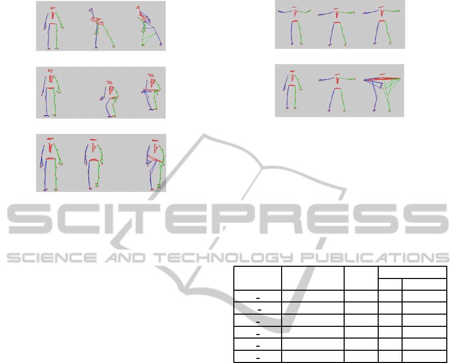
For comparison, we use some frames from each
motion sequence and label them by our method and
the method in(Li et al., 2005). Fig. 5 shows labeling
results when these two methods applied to the same
sequences of exercising, jumping and walking. As
the acquired data are quite different from the topo-
logical model, our method performs much better than
BIODEVICES 2011 - International Conference on Biomedical Electronics and Devices
292
a)
b)
c)
Figure 5: Labeling results for different motion sequence. a)
Shows the labeling results of exercising sequences. b) Illus-
trates the labeling results for jumping sequences. c) Shows
the labeling results of walking sequences. The topological
model used in the process of labeling is shown in the left.
The middle is the labeling result obtained by our methods.
The labeling result employed the method proposed in(Li
et al., 2005) can be found in the right.
the method proposed in(Li et al., 2005). We also la-
bel the acquired data which has different levels of dif-
ferences from the topological model using these two
methods. The results are given in Fig. 6. From the re-
sults, we can see that even slightly pose dissimilarity
can lead wrong identification using the method in(Li
et al., 2005), but our method works fairly well. The
comparison suggests that our approach is well-suited
for automatically labeling markers from 3D marker
trajectories without the requirement of pose similar-
ity.
To evaluate the accuracy of the method proposed
in this paper, we also applied our method and the
method proposed in(Li et al., 2005) to each frame
of different kinds of motion sequences and the re-
sults are shown in Table 1. From the table, we can
see that our approach performs much better than the
method mentioned in(Li et al., 2005) for all the tested
motions. Using the method proposed by us, all mo-
tion sequences are correctly labeled while the method
in(Li et al., 2005) can only label some or even no
frame. Experiment results show that the method pro-
posed in(Li et al., 2005) is very sensitive to pose sim-
ilarity while our method can work correctly even with
visually obviously different pose.
a)
b)
Figure 6: Different topological model and labeling results.
a) Shows the labeling results using the topological model
that are almost the same as the acquired data. b) Shows
the labeling results using the acquired data that are different
from the topological model with the upper body. The topo-
logical models, labeling results obtained by our method and
the results produced by the method of(Li et al., 2005) are
shown from left to right.
Table 1: Labeling results on different motion sequences.
BHL represents the method proposed by Baihua Li(Li et al.,
2005).
Subject ID Motion Frames
Labeled Frames
Ours BHL
14 20 Exercise 1500 1500 0
06 01 Walking 493 493 0
16 03 High Jumping 409 409 226
16 05 Long Jumping 294 294 116
14 02 Boxing 1000 1000 0
16 44 Running 215 215 0
5 CONCLUSIONS
We have proposed a fully-automatic method for la-
beling markers from their 3D trajectories using local
k-d trees in this paper. Our approach can work prop-
erly even when the captured subject is different from
topological model in pose and scale. The experiment
results show that our approach performs better than
the most closely related methods.
The method proposed in this paper is also very
suitable for the application of clinical gait analysis for
patients. First, the special pose that may be imprac-
tical for disabled people performing is not required
during capturing. Second, it is convenient by remov-
ing the step of motion calibration because patients es-
pecially disabled patients always have difficult in per-
forming motion calibration. Employing the method
proposed here, the only requirement for patients is
walking.
Our labeling method is based on the clustered
rigid bodies, but some rigid bodies are not strictly
BUILDING LOCAL K-D TREE FOR FLEXIBLY LABELING ARTICULATED POINT SETS
293

rigid, for example, the torso of human, especially
when the captured subjects perform vigorous exer-
cises like bending their body too low. In this situation,
our method may wrongly labeled markers attached to
these lax rigid bodies. However, the wrongly labeled
markers can be corrected using the constraint of tra-
jectories’ smoothness or solving the problem of abso-
lute orientation(Arun et al., 1987).
Our approach relies on the assumption that each
marker trajectory must be non-interrupted during the
whole motion. To accomplish the clustering task, we
also have to ask captured objects to exercise his joint
through the full range of motion. Although these
limitations are a little strict, but they can be satis-
fied in practice to ask the captured subject to perform
calibration motion in the middle of capturing area.
This requirementcan effectively reduce the number of
invisible markers and obtain almost non-interrupted
marker trajectories. For the task of clinical gait anal-
ysis, we should let the number of invisible markers
be as less as possible. In future work, we plan to re-
duce the limitations mentioned above in order to label
markers with noisy marker trajectories.
ACKNOWLEDGEMENTS
This work was supported by the Knowledge
Innovation Program of Chinese Academy of
Science(KGCX2-YW-610) and the National Key
Technology Research and Development Program of
China(2008BAI50B07).
REFERENCES
Aguiar, E. D., Theobalt, C., and Seidel, H.-P. (2006). Auto-
matic learning of articulated skeletons from 3d marker
trajectories. International Symposium on Visual Com-
puting, 1:485–494.
Arun, K., Huang, T., and Blostein, S. (1987). Least-squares
fitting of two 3-d point sets. IEEE Transactions on
Pattern Analysis and Machine Intelligence, 9(5):698–
700.
Bentley, J. L. (1975). Multidimensional binary search trees
used for associative searching. Communications of the
ACM, 18:509–517.
Bentley, J. L. (1990). K-d trees for semidynamic point sets.
In Proc.6th Ann. ACM Symp. on Computational Ge-
ometry, pages 187–197.
CMU, G. L. (2009). Motion capture database.
http://mocap.cs.cmu.edu.
Cox, G. S. and de Jager, G. (1992). A survey of point pattern
matching techniques and a new approach to point pat-
tern recognition. In COSMIG’92, Proc. South African
Symposium on Communications and Signal Process-
ing.
Gaede, V. and Gnther, O. (1998). Multidimensional access
methods. J. of Computer Surveys, 30(2):170–231.
Gleicher, M. (1999). Animation from observation: Mo-
tion capture and modtion editing. Computer Graphics,
33(4):51–55.
Guerra-Filho, G. (2005). Optical motion capture: Theory
and implementation. J. of Theoretical and Applied In-
formatics, 12(2):61–90.
Hornung, A., Sar-Dessai, S., and Kobbelt, L. (2005). Skele-
tal parameter estimation from optical motion capture
data. In VR’05,In: Proceedings of the IEEE Virtual
Reality Conference, pages 75–82. IEEE.
Kirk, A. G., O’Brien, J. F., and Forsyth, D. A. (2005).
Skeletal parameter estimation from optical motion
capture data. In CVPR’05,In: Proceedings of the
18th IEEE Conference on Computer Vision and Pat-
tern Recognition. IEEE.
Li, B., Meng, Q., and Holstein, H. (2003). Point pattern
matching and applicationsła review. In SMC’03,In:
Proceedings of the IEEE International Conference on
Systems,Man and Cybernetics.
Li, B., Meng, Q., and Holstein, H. (2004). Articulated pose
identification with sparse point features. IEEE Trans-
actions on Systems, Man, and Cybernetics PartB,
34(3):1412–1422.
Li, B., Meng, Q., and Holstein, H. (2005). Similarity
k-d tree method for sparse point pattern matching
with underlying non-rigidity. Pattern Recognition,
38(12):2391–2399.
Li, B., Meng, Q., and Holstein, H. (2008). Articulated
motion reconstruction from feature points. Pattern
Recognition, 41(1):418–431.
Mount, D., Netanyahu, N., and Moigne, J. (1999). Effi-
cient algorithms for robust feature matching. Pattern
Recognition, 32:17–38.
Ng, A. Y., Jordan, M. I., and Y.Weiss (2001). On spectral
clustering: Analysis and an algorithm. In NIPS’01,In:
Proceedings of the 15th Advances in Neural Informa-
tion Processing Systems, pages 849–856. MIT Press.
OMG (2009). Motion capture systems from vicon.
http://www.vicon.com/.
Wolfson, H. and Rigoutsos, I. (1997). Geometric hashing:
an overview. IEEE Transactions on Computational
Science and Engineering, 4(4):10–21.
Yu, Q., Li, Q., and Deng, Z. (2007). Online motion cap-
ture marker labeling for multiple interacting articu-
lated targets. Computer Graphics Forum (Proceedings
of Eurographics 2007), 26(3):477–483.
Zelnik-manor, L. and Perona, P. (2004). Self-tuning spectral
clustering. In Advances in Neural Information Pro-
cessing Systems 17, pages 1601–1608. MIT Press.
BIODEVICES 2011 - International Conference on Biomedical Electronics and Devices
294
