
RUNAWAY
A Web-based, Visual Programming System and Extensible Framework
for 3D Animation
Robert James Tucker
Department of Computing, The University of the West Indies, Mona, Kingston, Jamaica
Keywords:
Forward-kinematics, Visual programming, 3D Animation, Adobe Flash.
Abstract:
This paper describes the design and implementation of the initial prototype of Runaway: a visual program-
ming system for an extensible, web-based, 3D animation framework. Runaway is the first known project to
introduce jointed 3D character models as part of a visual programming system on the internet. The framework
provides a flexible, programmable, forward-kinematic model of jointed virtual bones. This model consists
of developer-defined discrete geometry and programmed behaviours that together enable scenes to be ren-
dered and manipulated. Character definitions with an arbitrary number of joints are supported, giving the user
fine-grained control. The system introduces beginner level programming to individuals, motivating them by
placing 3D characters within a scene that can be manipulated through introductory programming concepts
such as sequences, conditionals and loops. The current prototype of the Runaway framework is compact (less
than 5,000 lines of code), and runs on the Adobe Flash Platform.
1 INTRODUCTION
This paper introduces Runaway, a web-based visual
programming system which allows users to dynami-
cally control jointed 3D character models. The Run-
away project introduces a new way of creating a sta-
ble, dynamic, 3D forward-kinematic joint. This dis-
covery led to a novel approach to 3D character model
design in Adobe Flash.
In Runaway, a character model is composed of
a collection of 3D virtual joints which are defined
within a virtual glass case. This automates the char-
acter model animation calculations. The design of
two character models (the spider and the humanoid) is
outlined to highlight the versatility of the glass case.
Within the glass case, Runaway defines a seg-
ment as a combination of a character’s bone plus a
pivot around which the bone can rotate and the seg-
ment is contained within a bounding box. A char-
acter joint is composed from exactly two segments
that are contained within an internal container which
is then placed within an external container. The in-
ternal container supports axes of rotation about the Z
and the X axes. The external container handles rota-
tions about the Y axis. The joint can be extended with
another segment by placing the new segment and the
joint’s external container within a new internal con-
tainer. In this way an arbitrary collection of joints can
be defined. Recognisable character behaviours are de-
fined by restricting the arbitrary movement of partic-
ular joints.
Runaway’s design is based on two n-ary tree data
structures: the Character Model Tree and the Anima-
tor Tree. The Character Model Tree is a structural
representation of a character model and the Animator
Tree is the on-screen representation of a character’s
programmed behaviour. These two structures allow
fine-grained control over a Runaway character model.
The rest of this paper is organised as follows: sec-
tion 2 describes the background. Section 3 describes
the glass case, which defines the basic sections of a
character and how they are composed. Section 4 de-
scribes what a character model is and how it embodies
the glass case. Section 5 describes Runaway’s design.
Section 6 details the system’s implementation. Sec-
tion 7 states the contributions. Sections 8 and 9 de-
scribe related and future work respectively. Section
10 concludes the paper.
2 BACKGROUND
Project Runaway’s original goal was to develop a
system to address problems observed in Carnegie
36
James Tucker R..
RUNAWAY - A Web-based, Visual Programming System and Extensible Framework for 3D Animation.
DOI: 10.5220/0003304000360045
In Proceedings of the 3rd International Conference on Computer Supported Education (CSEDU-2011), pages 36-45
ISBN: 978-989-8425-49-2
Copyright
c
2011 SCITEPRESS (Science and Technology Publications, Lda.)
Mellon’s Alice (Conway et al., 2000) such as fre-
quent crashing. As the project’s scope increased, the
goal was modified to investigate the suitability of a
web-based platform to implement a visual program-
ming animation system comprising of jointed char-
acter models. Runaway was made internet-based to
facilitate worldwide access and to provide an alterna-
tive to the dataflow paradigm (Karam et al., 2008).
Dataflow is the only paradigm used by the internet-
based visual programming systems surveyed: Source-
Binder (Serenyi et al., 2010), Aviary Peacock (The
Aviary Team, 2010) and PointDragon (Gold et al.,
2010).
Runaway is aimed at beginning level program-
mers or those interested in animating 3D models
without having to learn object oriented programming.
Runaway is also suitable for use where someone
familiar with the software can sit side-by-side the
novice to tutor them with the software. Runaway is
aimed at beginning level programmers because pro-
gramming is an abstract activity and people learn vi-
sually (Smith et al., 2000).
Runaway is not intended to replace professional
grade 3D animation, or 3D model creation, as such
animation systems are aimed at experts.
2.1 Surveyed Adobe Flash-based Joints
A joint was identified as the primary unit for the Run-
away project. This is because it dictates how a char-
acter model is made and how the system would ma-
nipulate it.
Character model joints in Adobe Flash are created
or manipulated in 2 distinct ways:
• bone rigging.
• broken mesh modification.
In bone rigging, a singularly imported character
model is created in an external 3D modelling tool (e.g.
Blender) and had animations ascribed to its skeletal
structure. This method is unsuitable in Runaway be-
cause it would require a developer to anticipate every
possible movement a user would want. A main aim of
Runaway is to provide a user with fine-grained control
over his character models, and not merely animation
triggers.
In broken mesh modification, an imported 3D
mesh is modified at various points in its geometry to
create joints. There is a key flaw to this concept: it
was unable to make any other joint other than one
which went forward and back. This method is un-
suitable because Runaway aims at creating a general
joint, to simulate any kind of rotational movement
(e.g. a human shoulder) to further develop different
kinds of character model skeletons.
2.2 Joint Type
Runaway’s joints are forward-kinematic (Kamat and
Martinez, 2004). This is because inverse-kinematic
(IK) joints automatically reposition links in an artic-
ulated chain to attain a goal position (House et al.,
2009). As Runaway’s main philosophy is to allow
a user to have fine-grained control over a character
model’s position and pose, this makes IK unsuitable.
Since Runaway does not use the automatic reposition-
ing of IK, a Runaway user is encouraged to manually
manipulate each bone segment in order to see the sin-
gular effect of a command in action. This discrete ac-
tivity is designed to institute programming discipline.
IK also requires much more mathematical code in
which a developer would be involved than forward-
kinematic (FK). Additionally, the more calculations
required for a singular joint (in an Adobe Flash-
based environment) the higher the likelihood of sys-
tem slow-downs or crashes.
3 THE GLASS CASE
Runaway defines the glass case which allows a model
author to implement collections of FK joints. This
concept allows programmatic behaviours to be asso-
ciated with imported 3D geometry, to further create
skeletal structures called character models. The glass
case makes it possible for a user to be provided with
skeletal structures based on real-world objects, such
as arthropods and humanoids. Providing a system
with skeletal structures allows a user dynamic flexi-
bility over his character model to create unique ani-
mations.
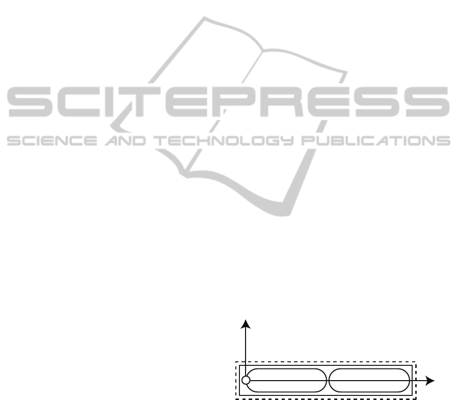
y
x
segment 1 segment 2
Figure 1: The Glass Case.
Figure 1 illustrates three axes, with the circle rep-
resenting the Z axis. The two geometries, segments 1
and 2 (that represent the bones), are by default con-
tained within their own bounding-boxes during addi-
tions to the scene.
The geometry of a segment has a point set at the
centre of all three axes to establish its pivot. Pivot
creation is done within a 3D modelling tool before
RUNAWAY - A Web-based, Visual Programming System and Extensible Framework for 3D Animation
37

the geometry is imported so that there is no need to
code its location inside Runaway. This results in less
lines of code and calculations for the system.
In figure 1, the position of segment 2 is offset by
the length of the first segment along the X axis. This
allows its pivot to be positioned at the end of segment
1. If segment 2 is not offset, the joint would not be
created and the two segments would compete for vis-
ibility within the 3D scene.
The solid box (internal container) is the ini-
tial container that encompasses the two geometries.
While being the initial representation of the forward-
kinematic joint, the internal container additionally
controls the rotations of the entire joint’s roll and
pitch. The dotted box (external container) controls
the yaw. Utilizing this method results in rotational
control and less code
1
.
No one box (internal container or external con-
tainer) has control over all three axes’ rotations be-
cause a yaw executes at an incline caused by the roll.
This is unsuitable for a user expecting to have fine-
grained control over a character model as appendages
(or a character model’s entire body) would behave un-
expectedly. If this was not done, an unexpected be-
haviour such as an appendage executing a yaw at an
affected incline could cause unintentional movement
through a character model’s body.
By default, all geometry is added to the centre of
the scene and positioned based on their pivot and ori-
entation. A geometry’s bounding-box does not inter-
fere with the operations of an internal or external con-
tainer, nor vice-versa. As it is the container, the glass
case performs rotations (such as yaw, pitch and roll)
on it to effect changes on a geometry’s position.
The glass case is designed to remove the need of
segment 2 to constantly calculate the position and ve-
locity of the end of segment 1. This is because Run-
away strives to perform the least number of glass case
calculations as possible during its runtime to allow
character models to visibly execute animation com-
mands and not overload the CPU.
A joint has two functions: to be able to perform
rotations for the entire joint and to be able to perform
rotations of segment 2. This simplicity gives the user
ease of control over the joint. Manipulating segment
1 is unnecessary, as its primary purpose is to allow
segment 2 to accurately calculate an offset position.
Segment 1’s secondary purpose is to act as the vi-
sual head of a joint in case the joint is connected to
1
Removing the external container reveals an alternative
method. During the execution of a yaw, the system could take into
account how much roll has been done. The roll could initially be
reversed and then redone after yaw executions. This method was
avoided as it incurred additional and unnecessary calculations.
a larger geometry such as a humanoid torso or an in-
sect’s thorax. If moving segment 1 were permissible,
a user would visibly distort the joint by making the
two areas look disconnected. This is bad because this
revokes the purpose of the glass case, which is to vi-
sually simulate a joint.
For a character model programmer, creating an
additional joint is straightforward. A new segment
should first be instantiated via the GUI, next an en-
tire joint should be added at the calculated end of that
segment. Finally, the programmer should insert this
entire structure into internal and external containers
of its own. This construct results in a new kind of
joint which visually consists of three segments and
two pivots. This approach can be extended to support
an arbitrary number of joints.
4 CHARACTER MODEL
A character model is based on the glass case. Run-
away defines a creature as being made up of an in-
terconnected system of joints. This interconnection
provides a user with skeletal structures which can be
manipulated as if they were marionettes. With hu-
manoid character models, ranges of behaviours can be
defined such as: walking, dancing, gymnastic-based
movements, as well as martial arts.
A user manipulates a character model’s segments
and entire body by combinations of yaw, pitch and roll
executions. These manipulations can be performed si-
multaneously, and this implementation is discussed in
section 6.3. The user has the ability to move the en-
tire model in six directions (forward, backward, left,
right, up and down) via controls and may perform
some of these activities in combination to move di-
agonally.
Segments and appendages are not allowed to exe-
cute the movement commands allowed by the body,
because this would cause dissection and Runaway
strives for realistic whole-body human and animal-
based animations.
4.1 Joint Usage
The glass case constructs the most general type of
joint which can be supported by the system. This gen-
eral joint is not restricted in rotational movement and
is used to represent a real-world construct, such as the
“ball and socket” human shoulders.
A model author is able to restrict the rotations to
define specific joints (such as a knee or an elbow) by
not providing the user with controls in the GUI.
CSEDU 2011 - 3rd International Conference on Computer Supported Education
38
At present Runaway includes two character mod-
els: the spider and the humanoid. The spider was cre-
ated as its modelling was easy to implement since it is
a jointed creature consisting of just a body and legs.
The humanoid demonstrates the flexibility of the Run-
away’s character model design.
4.2 Character Model 1: The Spider
To better create approximations of real-world spiders,
the geometry for a spider’s body is first added to the
Runaway’s scene. This gives a model author initial
bearings in order to add its legs. As Runaway’s ob-
jects exist in a virtual 3D space, bearings are useful
to model authors during the development of charac-
ter models as immediate observance of the effects of
a character model’s implementation is more powerful
than abstractly approximating.
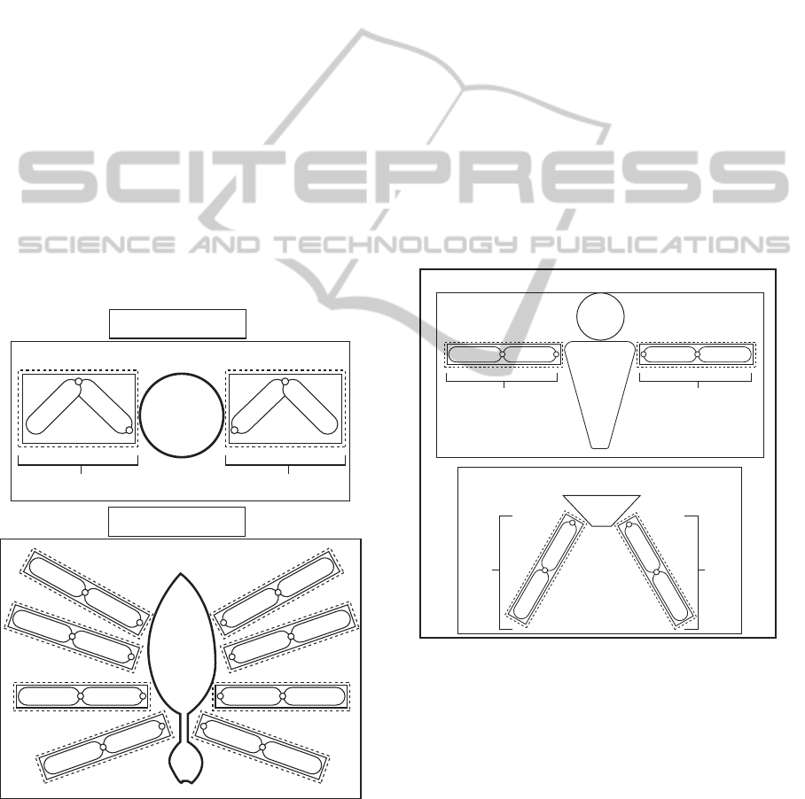
Though the spider’s body is designed in a 3D
modelling tool (Blender), it is represented in the glass
case as a larger object to which the legs are attached.
This is because the Runaway spider is defined as a
body surrounded by eight legs. This is displayed in
figure 2.
Body
Leg Leg
Body’s Bounding Box
Top View
Front View
Figure 2: The spider character model design.
Legs are modelled using independent glass cases.
These appendages are placed next to the body’s geom-
etry inside the body’s bounding-box. This facilitates
a unification which allows a user to refer to just the
container, if the entire body ever needs to be moved.
Referring to just the container also offers simplicity of
control, as a user would have had to refer to each area
of the spider simultaneously in order to move it. For
example, rotations would require the user to manually
maintain a leg’s proximity to the body. A user is not
allowed to refer to the contents of a container, unless
it is in terms of rotational control of a glass case. This
keeps the design of character models static and avoids
deformity, keeping a spider recognizable as a spider.
When attaching a spider’s leg, a secondary leg (for
a pair) is to be added to the opposite side of the body
for visual balance. The model author then estimates
the distances between each pair of legs to create dif-
ferent looking spiders.
4.3 Character Model 2: Humanoid
The Humanoid design gives the user control of the
character by simulating the major joints on a human
body (such as the waist, shoulders, knees and elbows).
LegLeg
Torso
Arm
Arm
Pelvis
Head
Torso’s
Bounding Box
Pelvis’ Bounding Box
Humanoid’s Bounding Box
Figure 3: The humanoid character model design.
Figure 3 shows how these joints use nested glass
case containers. This design is chosen to approxi-
mate the human skeleton. The design gives a user
puppeteer-like control over a 3D humanoid model. As
a result, a user has total dynamic control over a char-
acter model to give unique animations.
In Runaway, the included humanoid is defined as
having an upper and lower body. This allows a user
to affect control over one area without disturbing the
other. Limbs and legs are modelled using independent
glass cases and are placed inside the bounding-box of
RUNAWAY - A Web-based, Visual Programming System and Extensible Framework for 3D Animation
39
the torso and pelvis respectively. This gives unified
control similar to the spider’s design.
When upper and lower halves are assembled, both
are bound by a single container. Putting both halves
into one container gives unified control over the entire
body.
5 RUNAWAY’S DESIGN
Runaway’s design is based on the glass case, the
character model and three other major concepts: the
scene, and two internal data structures called the
Character Model Tree and the Animator Tree.
5.1 The Scene
A scene represents a window or a viewport. Runaway
uses the scene to display character models as they are
added or manipulated. The scene consists of two ob-
jects: a plane primitive, and a virtual camera.
5.1.1 The Plane Primitive
The plane primitive has two purposes: to simulate the
notion of the ground (to give the user a reference as to
which direction is up or down) and to act as a target
area during drag and drop operations. In this regard,
it works in tandem with the application development
framework that Runaway utilizes for GUI implemen-
tation (Adobe Flex). The plane primitive has been de-
fined as a drop target for a character model drag proxy
because its size relative to a mouse cursor makes it
easy for the user to manipulate.
In Adobe Flex, when a user drags an object over
a component, it becomes a possible drop target. Due
to the scene being a component customized as a 3D
viewport, there are empty areas within it. Adobe Flex
prohibits targeting empty areas within a component
because the drop target needs to evaluate whether or
not data being dragged to it is suitable, e.g., whether
a object being dragged consists of interpretable data.
A further example is a list row being dragged to a list
object; the list object would correctly identify the con-
tents of the list row as being in an interpretable format
because it came from another object which shares the
same parent class.
5.2 The Character Model Tree
The Character Model Tree (CMT) is a high-level rep-
resentation of a character model. The CMT is gener-
ated whenever a character model is added to a scene
to give the user an overview of the components that
humanoid
upper_bodylower_body
right_arm
humanoid . upper_body . right_arm
list of available commands
Figure 4: The Character Model Tree.
may be manipulated. The CMT is an abstract struc-
tural representation of the areas which may legally be
manipulated by a user, e.g., a character model’s leg
(its available commands are: yaw, pitch and roll for
realistic control).
The CMT’s purpose is to encourage the use of
Runaway’s programmatic controls to visualize an an-
imation. The direct manipulation of character model
parts can lead to the user not learning the basic pro-
grammatic concepts.
The CMT is an n-ary tree which visually acts as
the character model’s counterpart. A spider’s body
and eight legs, or a humanoid’s head, pelvis and torso
are represented by an n-ary tree.
Each node in the CMT (figure 4) consists of a la-
bel and part-specific commands. The label is used to
inform which area of a CMT was selected by the user
when identifying the point within a character model
with which a CMT node corresponds.
A node consists of part-specific commands to de-
scribe legal joint movement. For example, humanoid
knees and elbows are constrained because they are not
like ball-and-socket joints and as a result do not have
four directions of rotational freedom. A model de-
fined as humanoid would not behave as a human if it
contained in-humanly flexible joints.
A CMT is static because the character model does
not undergo modifications to its structure during its
existence in a scene. A static CMT identifies a char-
acter model to a particular group. Groups have identi-
cal part-specific commands defining identical abilities
for each member, e.g., upperBody:yaw to control the
yaw of a humanoid upper body.
5.3 The Animator Tree
The CMT is related to the Animator Tree (AT) by the
dragging of commands from the CMT to the AT.
CSEDU 2011 - 3rd International Conference on Computer Supported Education
40
this list holds dragged
commands from the
CMT
Figure 5: The Animator Tree.
The AT is a dynamically built n-ary tree which
handles dynamic executions of character model an-
imations. The tree iteratively processes the nodes
(command blocks) created to store character model
commands.
A user indirectly builds an AT whenever selecting
command blocks on the user interface. When a com-
mand block is found on the AT during traversals, it
is programmed to traverse its list object (the object in
which dragged commands are stored). In doing so,
these command blocks instruct Runaway how to exe-
cute character model part-specific commands.
AT command blocks are created so that the char-
acter model commands may have something in which
to be stored. This is important because during tree
traversals Runaway needs to locate the commands
per command block. When the tree is traversed, the
command blocks holding the character model com-
mands are first checked to determine how its com-
mand should be executed. The command blocks are:
iterative, simultaneous, while loop, and if statement.
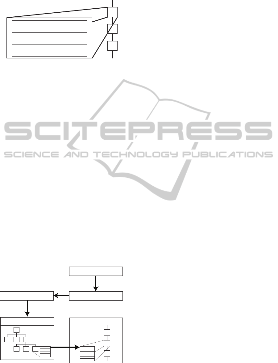
5.4 Core Component Relationships
The interactions of the major components are shown
in figure 6.
Animator Tree
The Character Model
The Glass Case
The Scene
Character Model Tree
Figure 6: The relationships between Runaway’s core com-
ponents.
When the user adds a character model to the scene,
the CMT is generated. This is to visually indicate its
usage as the next step towards animating a character
model. The selection of CMT nodes to reveal part-
specific commands follow this pattern of indication
in an attempt to reduce the need for worded visual
instruction, e.g., “look here” or “this is where you
should go”, which makes a GUI less intuitive.
By selecting a node on the CMT (e.g., a descrip-
tion of a character model’s leg) part-specific com-
mands are exposed which can then be dragged to a
command block of the AT.
When a tree traversal is initiated, the traversal
is temporarily paused until a command block self-
traverses its list of commands to execute a character
model animation. The main traversal is paused so that
a consequent command block is not processed. Pro-
cessing more than one command block at a time is
incorrect as it causes a visual anomaly when the char-
acter model tries to perform all the commands in the
ATs regardless of where within the AT a command
block execution currently is.
6 RUNAWAY’S
IMPLEMENTATION
The design areas discussed are: the scene, the CMT,
the inside of a CMT’s node, the AT, and the Traversal
Monitor.
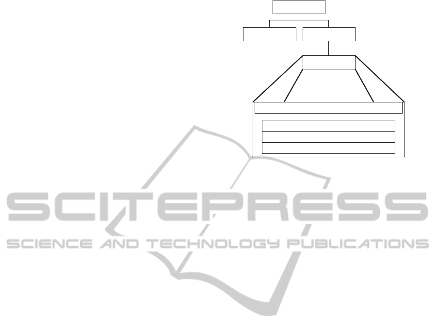
The scene comprises of an extended canvas object
and a panel as seen in figure 7(1). The canvas ob-
ject displays the 3D scene, while the panel acts as a
container for the canvas and clips objects which move
outside the view frustum of the virtual camera. This
is achieved by setting the canvas’ width and height to
the same amount of the panel. If this is not done, ob-
jects within the scene would move outside the panel
and appear in a conceptual layer above the rest of the
GUI objects in Runaway. Due to its appearance and
functionality, scene effectively resembles a virtual ba-
sic television set.
The extended canvas incorporates a 3D view space
(universe), a virtual camera, a 3D plane primitive
(ground) and a 3D positional cursor.
The 3D positional cursor provides a user with the
X and Z coordinates in the scene to add a character
model.
Positioning a character’s Y coordinate by de-
fault is unnecessary because Runaway establishes the
ground as a character model’s initial plane of exis-
tence. An additional use of the 3D positional cursor
is to offer a sense of direction to the user during move-
ment commands issued to the character model.
RUNAWAY - A Web-based, Visual Programming System and Extensible Framework for 3D Animation
41
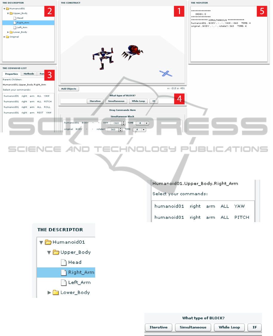
Figure 7: Runaway’s graphical user interface with the inserted spider and the humanoid character models.
6.1 Character Model Tree
The CMT is a tree component that is data-bound to
a tree model (scene-graph). Data binding makes the
tree component immediately display changes made to
the model. Figure 8 (figure 7(2)) shows the tree com-
ponent with a humanoid character model’s structural
description. Nodes in the CMT consist of a list object
displaying part-specific commands. These commands
are dragged to the AT for character model control.
Figure 8: The Character Model Tree.
6.2 Character Model Tree Node
A CMT node consists of three segments: a label, a
tree node and a list object.
The label is used as a visual indicator to tell the
user what part of the CMT has been selected and calls
the functions that tell the tree node to append a list ob-
ject to its structure and fill that object with particular
command data, e.g., humanoid:upperBody:yaw. This
is displayed by the component seen in figure 9 (figure
7(3)).
Figure 9: The Character Model Tree Node.
As the list object becomes visible depending on
the area of the CMT selected, the CMT node is
cleared upon the new selection of an area within the
CMT.
6.3 Animator Tree
The Animator Tree (figure 7(4)) comprises of a com-
mand block selector (CBS) and a command block
player (CBP).
Figure 10: The Command Block Selector.
The CBS (figure 10) comprises four command
blocks: iterative, simultaneous, while and if. When
selected, a command block is instantiated within the
CSEDU 2011 - 3rd International Conference on Computer Supported Education
42
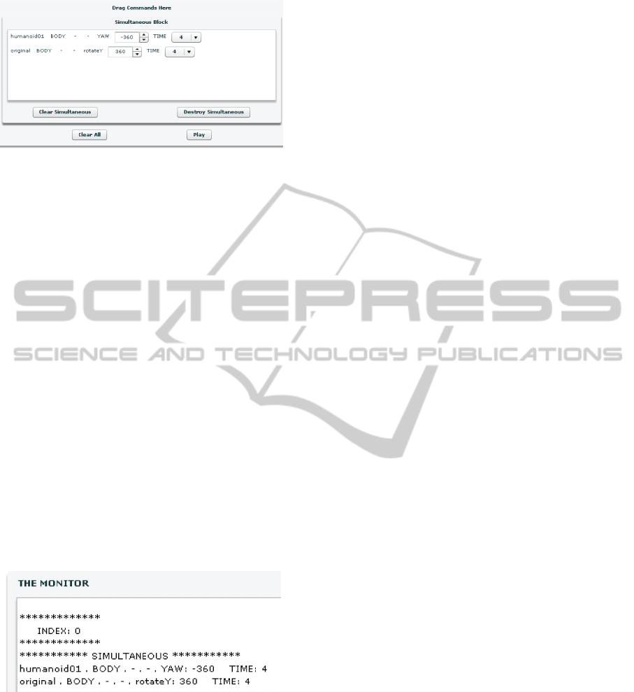
Figure 11: The Command Block Player.
CBP as an extended panel object with an empty list
object to store dragged commands. Command blocks
are appended to the tree node within the CBP. Figure
11 shows a simultaneous command block with two
commands which were dragged from the CMT.
A user creating character model animations results
in a uniquely constructed AT. ATs formed can be sin-
gle or multiple node command blocks. A forward spi-
ral rotation along the Z axis may be done in a single si-
multaneous command block when a character model
is instructed to move toward the virtual camera and
perform a roll. For two rolls, a user should instruct
the character model to roll and move 720 units to-
wards the camera with the least velocity so that the
spiral is made visible.
6.4 Traversal Monitor
The Traversal Monitor (TM) is responsible for dis-
playing the results of a AT node traversal. As seen in
figure 12 (figure 7(5)), it assists a Runaway developer
to pinpoint where in the traversal the Animator Tree
is and which command is being executed.
Figure 12: The Traversal Monitor.
The TM also informs the user what the system is
doing. This is helpful in cases where the user may
have caused the character model to move outside of
the view frustum and it is hard to tell if commands are
still executing or if minuscule movements are being
performed over long time periods.
7 CONTRIBUTIONS
The Runaway project provides three contributions:
• a different approach to creating a stable, dynamic,
3D forward-kinematic joint (glass case).
• a novel approach for character model design in
Adobe Flash.
• Runaway is the first known Adobe Flash-based
visual programming system that consists of 3D
jointed character models.
The glass case solves the problem in any OOP-
based 3D rendering framework that does not have a
joint creation mechanism or a method to attach 3D
objects to one another.
The glass case (along with the novel character
model design) solves the problem of a model author
having to create a new character model from scratch.
All that is needed is the skeleton design and a model
author is able to swap out the discrete 3D parts of
a character model. The skeleton will recalculate it-
self to change its overall appearance without the need
to retouch the skeletal code. Hence different look-
ing character models, belonging to the same skeleton,
could be produced rapidly and easily.
The novel character model design solves the prob-
lem of conceptually dissecting an entire mesh in real-
time (and during dynamic movement) to determine
which part of that model was colliding with another
object. This is because in the glass case, geometries
are already discrete and their bounding volumes can
be used as oriented bounding boxes (He, 1999).
Runaway provides an alternative to the dataflow
paradigm. A beginning level programmer does not
have to learn the dataflow paradigm to affect fine-
grained control over an object. Additionally, as Run-
away adopts some of Alice’s flavour of user interac-
tion, a user familiar with Alice can easily switch to
Runaway.
8 RELATED WORK
Runaway’s user interface was principally influenced
by Alice’s GUI and as a result has adopted much of
Alice’s flavour of user interaction (such as modular
control over character models using drag and drop).
Alice additionally influenced one of the project’s ear-
lier goal, which was to offer an alternative to dataflow,
because the author considered the dataflow paradigm
to be harder to learn. As Runaway is a internet-based
application and its character models are loaded dy-
namically, Runaway’s GUI file size of less than one
RUNAWAY - A Web-based, Visual Programming System and Extensible Framework for 3D Animation
43

megabyte remains constant. Alice is much larger, has
longer download periods and requires installation.
Alice is a desktop-based 3D graphics program-
ming environment aimed at beginning programmers
to stimulate interest in programming by manipulating
3D graphics. Both Alice and Runaway are animation
IDEs which can be used to animate 3D objects. In
both systems, users are able to drag and drop pro-
gramming elements in an execution area to perform
animations. Alice is used to introduce OOP concepts.
Both systems offer the animation of a 3D character
model as a reward for their use, and offer dynamic
animation to bolster creativity. However, Alice allows
its body parts to be dissected while Runaway does not
because of the glass case.
In the Karel Universe editor (Bergin, 2006), users
program by graphically composing code fragments to
control one or more robots in a rectangular 2D world
in order to engage students with the minimum amount
of syntactic load. It is similar to Runaway as both sys-
tems let the user see the effects of their program car-
ried out by objects in a 2D scene. However, Runaway
rewards a user by offering 3D-based characters via the
web, giving the feeling of marionette-based manipu-
lation. Runaway is a richer experience because it’s a
3D system, rather than a 2D system.
In Scratch (Malan and Leitner, 2007) users can
create animations, games, and interactive art via ma-
nipulating sprites using code on a 2D stage. Scratch’s
code fragment-like nature introduces the concept of
syntax to a user in the form of puzzle pieces, acting as
a gateway to OOP languages. While Runaway is not
aimed at encouraging syntax construction, Runaway
introduces the user to the dot operator to differentiate
which character model is being used, what segment
of the character model is being addressed and which
operations are to be carried out on that segment.
Runaway is not a constraint-based visual pro-
gramming language (Borning, 1995). The only con-
straints applied are to virtual joints and character
models to ensure that their respective body parts do
not fly apart (as in the Alice environment). Runaway’s
constraint specification is undertaken by a model au-
thor using the underlying programming language. A
Runaway user prescribes a series of activities upon his
selected character model to effect 3D animation.
Since a Runaway user dynamically commands a
character model to perform precise movements in any
pattern they wish, it cannot be said that Runaway fol-
lows the programming by example (PBE) paradigm
(Lieberman, 2001). In PBE, a user creates a move-
ment pattern with a series of gestures and then exe-
cutes the scene. A Runaway user finely controls each
segment of a character model by changing the rota-
tional position of that segment using sequentially or
simultaneously executed commands. This dynamic
approach is superior to PBE because in PBE new pat-
terns of movement would require a user to construct
an entire gesture, while in Runaway a user would sim-
ply edit or replace a command.
Runaway does not operate in a series of pauses
like PointDragon. PointDragon operates in a series of
pauses because it dynamically loads various aspects
of its GUI only when needed. Runaway’s operations
are in real-time and the commands are processed with
immediate effect. Aviary Peacock, SourceBinder and
PointDragon all lack character models to manipu-
late. Having interactive 3D characters to manipulate
in real-time is a much more compelling user experi-
ence.
Runaway does not use keyframes (Girgensohn and
Boreczky, 2000) to achieve animation. In Runaway,
the Animator Tree (AT) is designed to process dis-
crete commands sequentially. A Runaway user drags
these commands from the Character Model Tree to
any point inside any user-created AT node. The dif-
ference between keyframe-based animation and Run-
away’s method of animating is that Runaway’s com-
mands are each given a time period by the user to
complete. A user does not have to worry about suc-
cessive frames to achieve animation because Run-
away generates the necessary in-between incremental
movements during each command. This is done by
the underlying 3D animation engine (TweenMax).
9 FUTURE WORK
Runaway’s functionality will be improved by provid-
ing a user with the ability to create his own functions
in real-time. This will allow a user to create mod-
ular tasks, removing the need for repetitively defin-
ing controls for activities such as walking or running.
Additionally, the while loop command block will be
augmented to nest command blocks. This provides
the user with more modelling controls for scripting
the actions of a character model. Currently, to cause
a character model to perform repetitive complex ac-
tions (such as dancing), a user has to manually specify
the pattern inside multiple command blocks. The one
command block which allows for a singular instruc-
tion to be repeated is the while loop, but this too has
scope for improvement in the form of not being able
to cause simultaneous action, or if statement checks.
Providing modular tasks will solve this.
At the moment, Runaway does not have collision
detection implemented. As a character model is a col-
lection of discrete geometries bounded by the glass
CSEDU 2011 - 3rd International Conference on Computer Supported Education
44

case, the glass case can take advantage of the geom-
etry’s bounding-boxes to check for the intersection
of a geometry’s local bounding-box edge with an-
other. The bounding-boxes provided by the geome-
tries can allow the glass case to implement the ori-
ented bounding-box concept (He, 1999).
In the future, video recording functionality will be
added. This will allow a user to record and display
unique character model animations without running
the Runaway application or having access to the in-
ternet.
To gauge Runaway’s helpfulness, it is the current
intention to design and perform usage tests on object
oriented programming beginners to determine if pro-
gramming visually (in Runaway) provides a smoother
transition to text-based programming languages than
other available systems.
10 CONCLUSIONS
Runaway introduces the glass case which reduces the
number of joint manipulation calculations and the use
of forward-kinematics reduces the number of calcula-
tions that the developer has to be involved with. Char-
acter models provide visual objects that can be ma-
nipulated by the application of user controlled com-
mands. Inserting these character models into a Adobe
Flash-based, web-accessible visual programming sys-
tem allows any user to perform 3D manipulations on-
line. The implementation approach of Runaway has
led to a compact codebase of less than 5,000 lines of
code.
Runaway is an advanced prototype because it has
the ability to do general animations based around the
prototypical spider and humanoid character models.
ACKNOWLEDGEMENTS
The author would like to thank Huw Evans for his as-
tute guidance (without which the project would have
been largely unfocussed) and for his assistance in the
writing of this paper.
REFERENCES
Bergin, J. (2006). Karel universe drag & drop editor.
ITICSE ’06: Proceedings of the 11th annual SIGCSE
conference on Innovation and technology in computer
science education, pages 307–307.
Borning, A. H. (1995). The Programming Language As-
pects of Thinglab, a Constraint-oriented Simulation
Laboratory. ACM Trans. Programming Languages
and Systems, 3(4):353–387. ACM.
Conway, M., Audia, S., Burnette, T., Cosgrove, D., Chris-
tiansen, K., Deline, R., Durbin, J., Gossweiler, R.,
Koga, S., Long, C., Mallory, B., Miale, S., Monkaitis,
K., Patten, J., Pierce, J., Shochet, J., Staack, D.,
Stearns, B., Stoakley, R., Sturgill, C., Viega, J., White,
J., Williams, G., and Pausch, R. (2000). Alice:
Lessons Learned from Building a 3D System For
Novices. CHI 99.
Girgensohn, A. and Boreczky, J. (2000). Time-Constrained
Keyframe Selection Technique. Multimedia Tools
Appl., 11(3):347–358.
Gold, S., Liang, H., Gusev, V., and Baker, D. (2010). Point-
Dragon. http://www.pointdragon.com.
He, T. (1999). Fast collision detection using QuOSPO trees.
I3D ’99: Proceedings of the 1999 symposium on In-
teractive 3D graphics, pages 55–62.
House, B., Malkin, J., and Bilmes, J. (2009). The VoiceBot:
a voice controlled robot arm. CHI ’09: Proceedings
of the 27th international conference on Human factors
in computing systems, pages 183–192.
Kamat, V. R. and Martinez, J. C. (2004). Practical 3D
animation of multiply articulated construction equip-
ment. WSC ’04: Proceedings of the 36th conference
on Winter simulation, pages 1229–1237.
Karam, M. R., Smedley, T. J., and Dascalu, S. M. (2008).
Unit-level test adequacy criteria for visual dataflow
languages and a testing methodology. ACM Trans.
Softw. Eng. Methodol., 18(1):1–40.
Lieberman, H. (2001). Your Wish is My Command: Pro-
gramming by Example. Morgan Kaufmann Publishers
Inc., San Francisco, CA, USA.
Malan, D. J. and Leitner, H. H. (2007). Scratch for budding
computer scientists. SIGCSE ’07: Proceedings of the
38th SIGCSE technical symposium on Computer sci-
ence education, pages 223–227.
Serenyi, B., Kovari, B., Hernesz, G., Spitzer, D., Langh,
D., and Kelemen, V. (2010). SourceBinder: A node
based visual development environment for Flash 10.
http://sourcebinder.org.
Smith, D. C., Cypher, A., and Tesler, L. (2000). Program-
ming by Example: Novice Programming Comes of
Age. Commun. ACM, 43(3):75–81. ACM.
The Aviary Team (2010). Aviary Peacock.
http://www.aviary.com/userwiki/peacock.
RUNAWAY - A Web-based, Visual Programming System and Extensible Framework for 3D Animation
45
