PALM SHAPE COMPARISON FOR PERSON RECOGNITION
Irina Bakina
Moscow State University, Moscow, Russia
K
eywords:
Palm shape comparison, Flexible object, Alignment of palms, Person recognition, Combination of palm and
voice features, Bimodal approach.
Abstract:
The article presents a new method for palm comparison based on the alignment of palm shapes. The pro-
posed approach allows comparison and recognition of palms with sticking fingers. The existing methods
do not work correctly in this case, while it frequently appears in real environments (mostly among elderly
people). The idea of the proposed method is to model a ”posture” of test palm on reference palm. The form
of flexible object is used for palm modeling. This representation provides a convenient tool for applying palm
transformations and allows us to perform them in real-time mode. Low resolution webcams can be used for
palm image acquisition. The article also introduces the application of person recognition based on the pro-
posed comparison. At the end of the article the problem of improving recognition characteristics of palm is
addressed. Particularly, it provides a bimodal approach that employs palm and voice features.
1 INTRODUCTION
The article presents a new method for palm compar-
ison based on its shape. Comparison is performed
between reference and test palms. Reference palm
is a model of person’s palm stored in the form of flex-
ible object (Mestetskiy, 2009). This representation
of reference palm is constructed for a ”good” image
of palm, i.e. it doesn’t contain sticking fingers, long
nails, rings or bracelets. Contrarily, test palm is a bi-
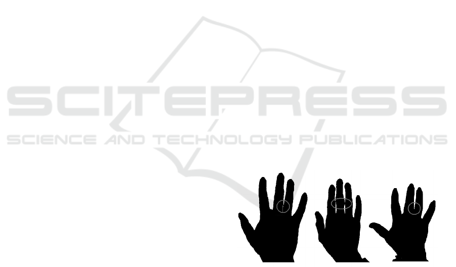
nary image of palm, which can contain sticking fin-
gers, like on Figure 1. Such case appears while deal-
ing with elderly people as sometimes it is difficult
for them to separate fingers. The proposed method
employs only palm shape information, interior is of
no interest. So, non-expensive webcams can be used
to obtain palm images.
The proposed method for palm comparison sug-
gests analyzing shapes of transformed reference palm
and test one. Transformation is performed for ref-
erence palm because it is a model of palm and we
know its structure; while it isn’t true for a test one.
Generally, when person presents his/her palm for
recognition, he/she does some or all of the follow-
ing movements: shifts and rotations of palm; rotations
of fingers. The used representation of reference palm
allows these movements to be modeled and, finally,
test and reference palms to be compared in the same
”posture”. The article continues the work, introduced
in (Bakina and Mestetskiy, 2009). Most existing ap-
Figure 1: Examples of sticking fingers.
proaches to palm recognition require to show palm
the way all fingers are well separated. The proposed
method for palm shape comparison can operate in
common cases with well separated fingers and, more-
over, it suits for cases with sticking fingers.
Palm shape isn’t really unique among peo-
ple. So, one-to-many comparison (or identification)
doesn’t provide good recognition accuracy. However,
the reducing of identification problem to verification
one may help. The possible way of doing this is com-
bining palm shape features with other biometric data.
As an example, a fusion of palm and voice features is
considered in the article.
The article is organized as follows. Section 2 con-
siders the background. In Section 3 the used model
of palm is described, and the construction of such
model is presented. In the next Section 4 comparison
of palms and similarity measure are introduced. Sec-
tion 5 describes the recognition system based on palm
shape comparison. Section 7 introduces the bimodal
5
Bakina I..
PALM SHAPE COMPARISON FOR PERSON RECOGNITION.
DOI: 10.5220/0003306100050011
In Proceedings of the International Conference on Computer Vision Theory and Applications (VISAPP-2011), pages 5-11
ISBN: 978-989-8425-47-8
Copyright
c
2011 SCITEPRESS (Science and Technology Publications, Lda.)

approach. Also, Sections 6 and 7 present the results
of the experiments carried out. Conclusion and future
work are considered in Section 8.
2 BACKGROUND
There are a lot of approaches to person recognition
based on palm features. The first one, which is widely
used nowadays, employs hand geometry features such
as palm width, perimeter, area, lengths and widths of
fingers, distances between finger joints, etc. This ap-
proach is introduced in several works—(Jianxia et al.,
2005), (Gonzalez et al., 2003), (Morales et al., 2008),
(Boreki and Zimmer, 2005), (Wong and Shi, 2002),
(Covavisaruch et al., 2005), (Varchol and Levicky,
2007), etc. Generally, the works differ in a set of hand
geometry features used, distance functions and classi-
fiers applied. For example, in (Morales et al., 2008)
information about width (measured at 40 locations) of
index, middle and ring fingers is considered. In (Co-
vavisaruch et al., 2005) feature vector is composed
of 21 components—length of fingers, width of each
finger at 3 locations, width of the palm. Also, sev-
eral distance functions are compared. In addition to
common hand geometry features special comparison
is performed for finger tips in (Wong and Shi, 2002).
Another approach to person recognition based on
palm features suggests transforming palm to prede-
fined position and extracting shape-based features
(Yoruk et al., 2006), (Jain and Duta, 1999), (Mestet-
skiy, 2007), (Su, 2008). In this case a contour of palm
is taken as a signal, to which independent component
analysis, wavelet, cosine or other transforms are ap-
plied. But most of the existing approaches can oper-
ate only in situations when person presents his palm in
a such manner that obtained image is good. At least it
means that fingers are well separated, i.e. don’t touch
each other. For a ”good” palm it is possible to calcu-
late features correctly and, then, apply some classifier
to perform recognition.
Hand geometry features don’t suit for person
recognition in the case of sticking fingers, because we
don’t know the exact position of fingers and, there-
fore, can’t calculate their characteristics. However,
shape-based approach gives hope to us, because the
shape of palm is known, even when there are fingers
touching each other.
Shape-based approach was introduced in several
works. In (Yoruk et al., 2006) it is proposed to apply
transform features for a normalized palm for recog-
nition purposes. Normalization includes initial orien-
tation of whole palm, orientation of fingers by their
eigen values (rotation of fingers at their pivot points)
and alignment of two palms by their centroids and
pivot lines. The authors compare recognition ac-
curacy for modified Hausdorff distance and two ar-
chitectures of the Independent Component Analysis.
The obtained correct identification and verification
accuracies were about 98 − 99% depending on the
size of feature vector for the Independent Component
Analysis.
Another approach is introduced in (Jain and Duta,
1999). In this work it is suggested extracting five
pairs of corresponding fingers and aligning them sep-
arately. Alignment for each pair of fingers is based
on quasi-exhaustive polynomial search of point pair
matching between the two sets of points. Least-
squares type distance is used to provide analytical so-
lution to the alignment problem. The average distance
between the corresponding points is used as measure
of similarity of two palms. Threshold rule is ap-
plied for verification. FAR (False Accept Rate) and
FRR (False Reject Rate) curves are presented for dif-
ferent values of a threshold. For the threshold equal to
1.8 the obtained FAR is about 2%, while FRR is near
to 3.5%.
In (Mestetskiy, 2007) reference and test palm to
be compared are transformed to a predefined position,
where angles between fingers are fixed. This is done
by performing rotations of fingers at their bending
points. Then, the palms are aligned. After that nor-
malized symmetric difference of their superposed sil-
houettes is calculated. Nearest neighbor approach and
threshold rule are applied for classification. The ob-
tained EER (Equal Error Rate) is about 5%.
In all these approaches reference and test palms
are supposed to be of the same nature (set of contour
points, flexible objects, etc). Generally, transforma-
tions are performed or can be performed for both of
them. However, these approaches require no sticking
fingers and long finger nails. Ring removal technique
is introduced only in (Yoruk et al., 2006).
The approach to palm shape comparison, pro-
posed in this article, can be used in cases of stick-
ing fingers. It is based on the same idea of align-
ment of palm shapes for comparison. We assume that
reference palms don’t have fingers that touch each
other, while test ones can have them. Transforma-
tions reflect possible movements of palm. They are
performed for a reference palm to provide the best
alignment with a test palm.
3 MODEL OF PALM
The model of palm, which is constructed for a refer-
ence palm, is proposed in (Mestetskiy, 2009). It is the
VISAPP 2011 - International Conference on Computer Vision Theory and Applications
6
form of flexible object, based on the circular decom-
position of binary image. Further, we consider some
definitions, which are used in the article.
3.1 Basic Definitions
Consider a set of points T on the Euclidian space R
2
such that it is connected planar graph. The graph
contains a finite set of vertices and continuous edges.
Edges can intersect only at graph vertices. Each point
t ∈ T is associated with circle c
t
with the center at this
point.
Family of circles C = { c
t
, t ∈ T} is called the cir-
cular graph. Graph T is called the axial graph or
skeleton of a circular graph. The union of circles
S =
S
t∈T
c
t
with their interior is called the silhouette of
a circular graph. So, silhouette of a circular graph is
a close connected set of points on the Euclidian space
S ⊂ R
2
. The boundary of a circular graph is the en-
velope of all circles in the family C. The allowed set
of transformations of a circular graph that preserve its
topological structure and make the group, is called de-
formations. Denote a set of deformations by V. Flex-
ible object G = {C, V} is a circular graph and its set
of deformations.
In the proposed approach to palm comparison it
is possible to apply such transformations of flexible
object that don’tpreserve its topological structure. So,
let a set of deformations V be a set of transformations
that make a group.
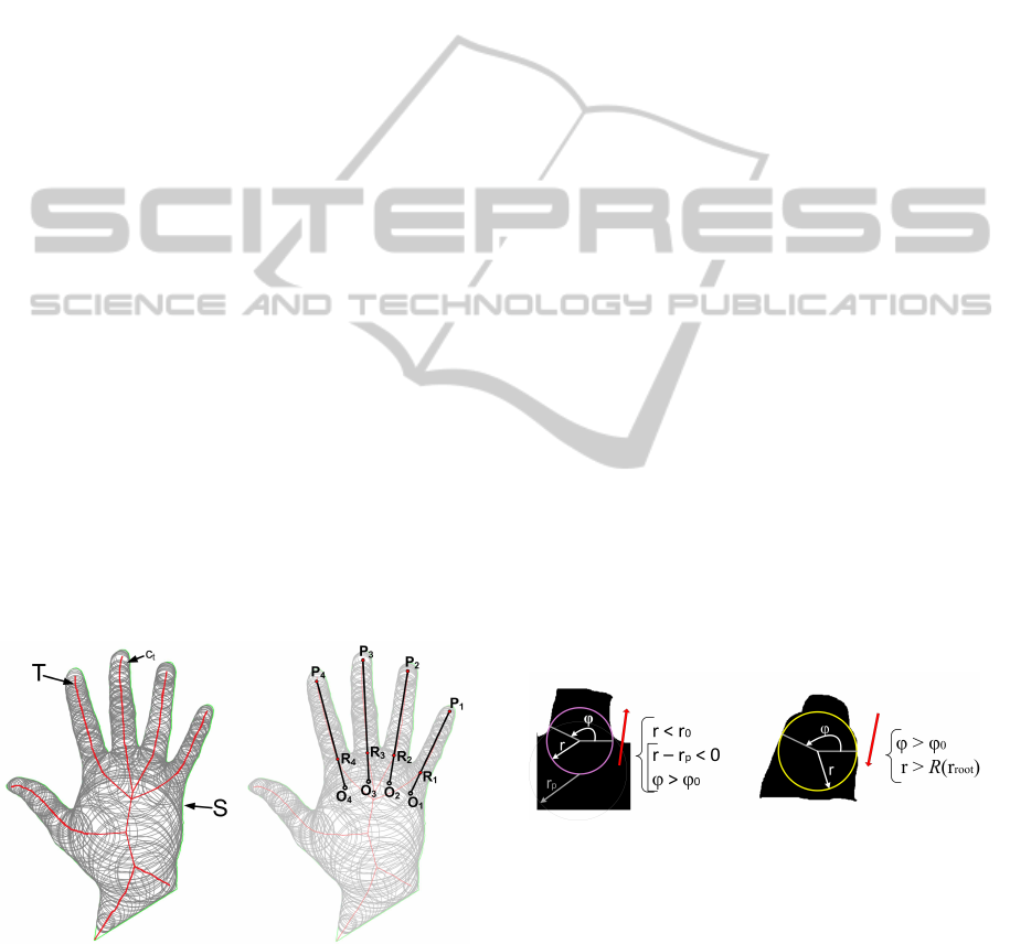
Figure 2 (on the left) shows an example of flexi-
ble object. It contains its axial graph T and family of
circles C (only circles associated with graph vertices
are present).
Figure 2: Example of flexible object (on the left) and its
marking (on the right).
Thus, to define the flexible object of palm it is
necessary to describe the allowed set of transforma-
tions T.
3.2 Palm Transformations
In the proposed system person shows his/her palm
by positioning it on a horizontal surface. So, basic
movements of palm can only include, as it was de-
scribed earlier, shifts and rotations of palm, rotations
of fingers. Thus, a set of transformations to be defined
should allow all these movements to be modeled.
First, rotation points of four fingers (index, mid-
dle, ring and little) are calculated. This points are the
roots of finger proximal phalanges. Fingers are ro-
tated at this points. Thumb finger isn’t considered, as
its movements are more complex and can result in the
significant change of palm shape (for example, skin
changes between index and thumb fingers).
The procedure of extracting tips, roots and ro-
tation points of fingers is described in (Bakina and
Mestetskiy, 2009). It is assumed that the rotation
point of a finger lies on its axe, and the distance be-
tween rotation point and root of the finger is 30% of
the finger length. Here, axis of a finger is a line that
connects its tip and root. On Figure 2 (on the right) ro-
tation points are marked as O
1
, O
2
, O
3
and O
4
. Points
R
1
, R
2
, R
3
and R
4
are root points of fingers; points
P
1
, P
2
, P
3
and P
4
are tips of fingers; lines O
1
P
1
, O
2
P
2
,
O
3
P
3
and O
4
P
4
are axes of fingers.
It should be noted that tips and roots of fingers are
detected automatically by analyzing the palm circu-
lar graph. In short, the branch of the circular graph is
considered from its branchpoint to leaf node. The first
vertex to fulfil the restrictions on radius r of the cir-
cle and angle ϕ between two segments connecting the
center of circle with its tangency points is treated as
the root of a finger. Then, the branch is analyzed in
opposite direction and similar restrictions are applied
to extract the tip of a finger.
Figure 3: Detection of root (on the left) and tip (on the right)
of a finger.
Figure 3 illustrates the restrictions applied. Here,
r is the radius of the current circle on the branch; ϕ is
the angle between two segments connecting the center
of a circle with its tangency points; r
p
is the radius of
the previous circle; r
0
and ϕ
0
are restrictive constants;
r
root
is the radius of the found root vertex; R(x) is
a function. In the current work R(x) = 0.65x.
So, the allowed set of transformations includes
shifts and rotations of whole palm, and rotations of
PALM SHAPE COMPARISON FOR PERSON RECOGNITION
7
fingers at points O
1
, O
2
, O
3
and O
4
. It is assumed
that the structure of polygon O
1
O
2
O
3
O
4
is fixed.
Figure 4: Parametrization of palm: initial (on the left) and
assumed (on the right).
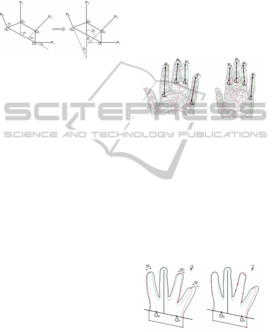
Let a vector
−→
α = (α
1
, α
2
, α
3
, α
4
) be a set of an-
gles between finger axes and line O
1
O
4
. This angles
are shown on Figure 4 (on the left). Then, by v(
−→
α )
define the transformation that rotates the fingers to
the angles
−→
α . E
i
is the initial (not transformed) ref-
erence palm, where E = {E
i
}
n
i=1
is the set of refer-
ence palms in the database; by v(E
i
,
−→
α ) define the
flexible object, which is the result of transformation
v(
−→
α ) applied to E
i
. The allowed values of
−→
α de-
fine the set D
i
⊂ R
4
and group of transformations
V
i
= {v(
−→
α )}
−→
α ∈D
i
; D =
n
S
i=1
D
i
, V = {V
i
}
n
i=1
.
4 PALM SHAPE COMPARISON
Palm shape comparison is performed for reference
and test palms. Reference palm is in the form of flexi-
ble object, while test palm is a binary image. The idea
is to transform reference palm to provide the best
alignment with test one.
Let F be a test palm and µ(E
i
, F) a measure, which
defines the distance between reference palm E
i
and
test palm F. So, we have the minimization problem:
−→
α
∗
= argmin
−→
α ∈D
i
µ(v(E
i
,
−→
α ), F) (1)
Here,
−→
α
∗
corresponds to transformation, which
produces the best alignment of palms.
Further, we assume that angle α
3
between axe
of middle finger O
3
P
3
and O
1
O
4
is fixed (as person
rarely moves his middle finger). Thus, optimization
problem (1) can be reduced to minimization by three
parameters:
−→
β = (β
1
, β
2
, β
4
), where β
1
= α
3
− α
1
,
β
2
= α
3
− α
2
and β
4
= α
3
− α
4
, which are shown on
Figure 4 (on the right). The optimization problem (1)
is solved by setting the initial approximation for
−→
β
and, then, by finding the optimal value
−→
β
∗
in a small
local region.
For the initial approximation of
−→
β the angles be-
tween fingers on a test palm are taken. Certainly,
these angles can be easily calculated for a reference
palm. However, we can obtain approximate values of
them for a test palm too. To do this, firstly, circu-
lar decomposition of test palm is created. Then, ap-
proximate position of fingers axes are extracted by the
same procedure as for a reference palm. This axes are
approximate, because in the case of sticking fingers
we can’t calculate finger roots correctly.
Figure 5: Extraction of approximate finger axes for test
palms.
Figure 5 illustrates the extraction of finger axes for
a test palm. Points Q
1
, Q
2
, Q
3
and Q
4
were marked
as supposed finger roots. Approximate axes are Q
1
P
1
,
Q
2
P
2
, Q
3
P
3
and Q
4
P
4
.
So, initial approximate value
−→
β
0
for
−→
β is set. To
compare the reference palm E
i
with the test palm F
we apply transformation v(
−→
β
0
) to the reference palm
and superpose middle fingers of both palms (i.e. tips
and axes of middle fingers). Then, the region of palms
that lies under line O
1
O
4
of reference palm is cut on
both palms. Wrist regions of palms have different
structure, explained by the presence of long sleeves,
watches, etc. So, only the region that corresponds to
four fingers is analyzed. Figure 6 shows initial align-
ment of palms (on the left). Only region above line
O
1
O
4
is taken into account.
Figure 6: Initial (on the left) and optimal (on the right)
alignment of palm regions.
The distance between palms is defined as symmet-
VISAPP 2011 - International Conference on Computer Vision Theory and Applications
8
ric difference of regions of their matched silhouettes:
µ(E
i
, F) = Area(E
i
\F) + Area(F\E
i
) (2)
Function ”Area” in (2) calculates area of region above
O
1
O
4
.
The proposed alignment of palms allows us to
consider parameters β
1
, β
2
and β
4
independently.
The local region, in which optimal value of
−→
β
is searched, is spacial parallelepiped: β
i
∈ [β
0
i
−
∆β
i
;β
0
i
+ ∆β
i
], i = 1, 2, 4. Basically, ∆β
i
reflects the
error of calculating angles between fingers on a test
palm. The allowed values were set to ∆β
1
= ∆β
2
=
∆β
4
= 5
◦
. The experimental results have shown that
deviation of 5
◦
is enough to achieve the best align-
ment of palms.
The optimal value of β
i
in the segment [β
0
i
−
∆β
i
;β
0
i
+ ∆β
i
] is found by iteration procedure. Angles
from β
0
i
− ∆β
i
to β
0
i
+ ∆β
i
with step of 2
◦
are exam-
ined. The angle to produce the best alignment of palm
regions is taken as optimal. So, the optimal vector
−→
β
∗
is found. Figure 6 (on the right) shows the obtained
optimal alignment of palms.
5 PERSON RECOGNITION
The described above method for palm shape compar-
ison is employed in the proposed recognition system.
This system works as follows.
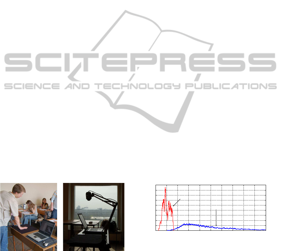
Person positions his/her palm on a monochrome
horizontal surface for recognition. Webcam, which
is situated above person’s palm, makes image of it.
Figure 7 shows the proposed system.
Figure 7: Person recognition system.
The acquired palm image, or test palm, is trans-
formed to binary image and compared to database
of reference palms. Database of reference palms con-
sists of persons’ palms in the form of flexible ob-
ject, and can include several models for each per-
son. When test palm is compared to reference palms
of a particular person, the closeness of ”reference”
and ”test” person is defined as the minimal distance
between test palm and each of the existing reference
palms of this particular person.
Then, simple threshold rule is applied to deter-
mine, if the presented test palm belongs to one of
the users. In the case when database contains more
than one similar person preference is given to the
nearest one. If person isn’t recognized as an insider
within several seconds (while several palm images
are made and passed for recognition), this person is
treated as an outsider.
The acquired palm images are scaled for recogni-
tion. So, additional camera calibration is required.
6 EXPERIMENTS
Experimental data contained 255 palm images of
54 persons. These images were divided into two
groups—reference and test data. Reference data was
composed of 108 palms (1− 3 images for every user);
so, test data contained 147 images.
Firstly, the distance between each test palm and
each user (the minimal distance between test palm
and each of the existing reference palms of this par-
ticular user) was calculated. It was done for differ-
ent values of threshold. After that densities of dis-
tribution for intra- and inter-class distances were esti-
mated. Every class is composed of all palms for a par-
ticular person. So, when test and reference palms be-
longed to the same person, the distance was consid-
ered to be intra; otherwise, it was inter-class distance.
There were 147 intra-class and 7791 inter-class dis-
tances. The distance is measured in square pixels.
0 5000 10 000 15 000 20 000 25 000 0 5000 10 000 15 000 20 000
0
0.0002
0,0004
0,0006
0,0008
0,001
0,0012
0,0014
0,0016
0,0018
Distance
Intra
Inter
Figure 8: Density of distribution for intra- and inter-class
distances.
As a result, intra- and inter-class distances turned
out to be really separable (see Figure 8). In the next
experiments recognition accuracy was estimated—
FAR and FRR were calculated for verification and
identification processes.
PALM SHAPE COMPARISON FOR PERSON RECOGNITION
9

6.1 Verification
For each test palm verification was executed for dif-
ferent values of threshold. Incorrect verification was
registered during FRR estimation, if the minimal dis-
tance between person’s test palm and his/her refer-
ence palms was greater than the considered threshold.
Incorrect verification was registered during FAR es-
timation, if the minimal distance between test palm
and reference palms of another person was less than
the considered threshold. Figure 9 shows the obtained
values of FAR and FRR.
1500 1550 1600 1650 1700 1750 1800
0
1
2
3
4
5
6
Threshold
%
FRR
FAR
Figure 9: FAR and FRR in verification process.
The results show that the proposed method can
produce verification accuracy near to 99% when
threshold value is about 1600−1700. To make a com-
parison, total palm area is about 40000 square pixels,
so, the threshold value of 2000 allows the deviation
of 5% between palm silhouettes. The obtained value
of EER (Equal Error Rate) is 0.5%.
6.2 Identification
Identification was executed for all test palms for dif-
ferent valuesof threshold. Incorrect identification was
registered during FRR estimation, if the nearest ref-
erence palm, which met the threshold, didn’t belong
to the same person. Incorrect identification was reg-
istered during FAR estimation, if the list of nearest
reference palms, which met the threshold, contained
palms of other persons.
1200 1250 1300 1350 1400 1450 1500 1550 1600 1650 1700
0
5
10
15
20
25
30
35
40
Threshold
%
FRR
FAR
Part of palms,
which meet the threshold
Figure 10: FAR, FRR and relative amount of reference
palms, which meet the threshold in identification process.
Figure 10 shows the obtained results. The min-
imal value of FRR is about 5%, and it is explained
by the presence of really similar palms in database.
The exclusion of similar palms produced better results
with FRR about 0%.
Nevertheless, FAR remains high. Even when the
nearest person from the database for the test palm
is recognized correctly, there is amount of reference
palms similar to test one (i.e. distances meet the
threshold). And, mostly, it is the nature of this modal-
ity. Only palm shape isn’t enough to produce reliable
decision about person’s identity. There can be differ-
ent solutions to the problem of high FAR. One of them
is combining different modalities.
7 COMBINING MODALITIES
We propose combination of palm and voice features
to decrease the FAR value. In addition to presenting
palm for recognition purposes, person is required to
say a password. So, text-dependent person recogni-
tion can be applied (Theodoridis and Koutroumbas,
2003).
Each person in the database is described by sev-
eral reference models of palm and several records
of password. Combination of modalities implements
cascade model, where voice features serve as filter
of knowingly unlike persons; and, then, recognition
is performed over palm shape within a small group.
Voice features are composed of cepstral coefficients,
calculated for audio signal of password. DTW (Dy-
namic Time Warping) technique is used to compare
passwords.
At first, test record of password is compared to
records for each person in the database; and the list
of k most similar persons is constructed. Then, iden-
tification is performed for test palm within the group
of these persons.
Table 1: FAR and FRR for bimodal recognition.
k m FRR, % FAR, %
3 1600 6.7 0
4 1600 6.7 0
5 1600 6.7 0
3 1700 4.2 0
4 1700 4.2 0
5 1700 4.2 0
3 1800 3.4 0
4 1800 3.4 5
5 1800 3.4 6.7
3 1900 1.7 1.7
4 1900 1.7 6.7
5 1900 1.7 8.4
Experiments for bimodal recognition were carried
out for a smaller group of users, as reference and test
VISAPP 2011 - International Conference on Computer Vision Theory and Applications
10

records of passwords were existed only for 20 people.
As a result, there were 38 reference persons and 117
test objects. Experiments were carried out for differ-
ent values of parameter k and threshold m. Table 1
shows the best obtained values of FAR and FRR for
bimodal recognition.
As it is expected, bimodal approach shows better
results than unimodal. Combination of two modalities
allowed us to reduce the high value of FAR. For ex-
ample, for several values of k and m it is equal to 0%.
Also FRR is less than it was for unimodal identifica-
tion. For k = 3 and m = 1900 we have ERR = 1.7%.
8 CONCLUSIONS
The new method for person recognition by palm
shape was proposed. The choice of palm shape is ex-
plained by the fact that there are people, who tend to
show palm ”poorly”. In such cases (presence of stick-
ing fingers, incomplete wrist, etc.) sometimes it is
impossible to measure or generate palm features for
future comparison. The proposed method allows ref-
erence palm (stored in the form of flexible object) and
test palm (which is a binary image, or a flexible object
too) to be compared. The idea is to transform refer-
ence palm to provide the best alignment with test one.
Verification accuracy in terms of EER was shown
to be about 0.5%. For identification purposes person
palm shape isn’t really unique, so FRR was near 5%.
FAR remains high and can be reduced by combin-
ing palm shape features with other biometric data.
One of the possible combinations, with voice features,
was illustrated. The best recognition accuracy for bi-
modal recognition was EER = 1.7%.
The experiments were carried out on the prototype
of the system. It is a real-time application, the ”Time
& Attendance” system, which traces the presence of
students at the classes.
In the future it is supposed to implement align-
ment of two palms, which will consider possible ro-
tations of middle finger and, moreover, which will
model the complex movements of thumb. Also, other
decision rules should be studied (instead of simple
threshold rule applied). The presence of some arti-
ficial things on palm (such as rings, bracelets, etc.)
should be investigated.
ACKNOWLEDGEMENTS
The author thanks the Russian Foundation of Basic
Researches, which has supported this work (grants
08− 01− 00670 and 10− 07− 00609).
REFERENCES
Bakina, I. and Mestetskiy, L. (2009). Palm comparison in
the presence of artifacts (in russian). In Proceedings of
the 14th Russian Conference of Mathematical Meth-
ods of Pattern Recognition, Suzdal, September 21-26,
2009, pages 301–304.
Boreki, G. and Zimmer, A. (2005). Hand geometry: A new
approach for feature extraction. In Proceedings of the
4th IEEE Workshop on Automatic Identification Ad-
vanced Technologies, pages 149–154.
Covavisaruch, N., Prateepamornkul, P., Ruchikachorn, P.,
and Taksaphan, P. (2005). Personal verification and
identification using hand geometry. In ECTI Transac-
tions on Computer and Information Technology, vol-
ume 1, pages 134–140.
Gonzalez, S., Travieso, C. M., Alonso, J. B., and Ferrer,
M. A. (2003). Automatic biometric identification sys-
tem by hand geometry. In Proceedings of the 37th An-
nual International Carnahan Conference on Security
Technology, pages 281–284.
Jain, A. K. and Duta, N. (1999). Deformable matching of
hand shapes for verification. In Proceedings of ICIP
’99, Kobe, Japan, pages 857–861.
Jianxia, W., Wanzhen, Z., Xiaojun, W., and Min, Q. (2005).
The feature parameter extraction in palm shape recog-
nition system. In Journal of Communication and
Computer, volume 2, pages 25–28.
Mestetskiy, L. (2007). Shape comparison of flexible ob-
jects. In VISAPP, volume 1, pages 390–393.
Mestetskiy, L. (2009). Continious morphology of binary im-
ages: figures, skeletons, circulars (in Russian). FIZ-
MATLIT, Moscow.
Morales, A., Ferrer, M. A., Diaz, F., Alonso, J. B., and
Travieso, C. M. (2008). Contact-free hand biometric
system for real environments. In Proceedings of the
16th European Signal Processing Conference (EU-
SIPCO).
Su, C.-L. (2008). Index, middle, and ring finger extrac-
tion and identification by index, middle, and ring fin-
ger outlines. In VISAPP, volume 1, pages 518–520.
Theodoridis, S. and Koutroumbas, K. (2003). Pattern
Recognition. Elsevier, 2nd edition.
Varchol, P. and Levicky, D. (2007). Using of hand geometry
in biometric security systems. In Radioengineering,
volume 16, pages 82–87.
Wong, A. L. and Shi, P. (2002). Peg-free hand geome-
try recognition using hierarchical geometry and shape
matching. In Proceedings of IAPR International Con-
ference on Machine Vision Applications, pages 281–
284.
Yoruk, E., Konukoglu, E., Sankur, B., and Darbon, J.
(2006). Shape-based hand recognition. In Image Pro-
cessing, IEEE, volume 15(7), pages 1803–1815.
PALM SHAPE COMPARISON FOR PERSON RECOGNITION
11
