
USING OPAQUE IMAGE BLUR FOR REAL-TIME
DEPTH-OF-FIELD RENDERING
Martin Kraus
Department of Architecture, Design and Media Technology, Aalborg University
Niels Jernes Vej 14, 9220 Aalborg Øst, Denmark
Keywords:
Depth of field, Blur, Glow, Visual effect, Real-time rendering, Image processing, GPU, Pyramid algorithm.
Abstract:
While depth of field is an important cinematographic means, its use in real-time computer graphics is still
limited by the computational costs that are necessary to achieve a sufficient image quality. Specifically, color
bleeding artifacts between objects at different depths are most effectively avoided by a decomposition into sub-
images and the independent blurring of each sub-image. This decomposition, however, can result in rendering
artifacts at silhouettes of objects. While various algorithms have been suggested to eliminate these artifacts,
we propose a new blur filter that increases the opacity of all pixels to avoid artifacts at the cost of physically
less accurate but still plausible rendering results. The proposed filter is named “opaque image blur” and is
based on a glow filter that is applied to the alpha channel. We present a highly efficient GPU-based pyramid
algorithm that implements this filter for depth-of-field rendering.
1 INTRODUCTION
Depth of field in photography specifies the depth
range of the region in front and behind the focal plane
that appears to be in focus for a given resolution of
the film. As limited depth of field is a feature of all
real camera systems (including the human eye), plau-
sible depth-of-field effects can significantly enhance
the illusion of realism in computer graphics. More-
over, limited depth of field can be used to guide the at-
tention of viewers. In fact, it is routinely used for this
purpose in movies — including computer-animated
movies. In recent years, it has also been used in sev-
eral computer games and first applications in graphi-
cal user interfaces have been demonstrated.
There are various approaches to the computa-
tion of depth-of-field effects, which provide differ-
ent trade-offs between image quality and rendering
performance. Current techniques for real-time per-
formance are based on a single pinhole image with
infinite depth of field since the performance of this
approach is independent of the scene complexity and
graphics hardware is optimized to compute this kind
of imagery. One of the most prominent rendering ar-
tifacts in this approach is color bleeding between ob-
jects at different depths.
One way to avoid these particular artifacts is the
decomposition of the pinhole image into sub-images
according to the depth of pixels and the independent
processing of each sub-image. The main remaining
artifact is caused by partial occlusions. More specif-
ically, the problem is caused by pixels of one sub-
image that are occluded by the pinhole version of an-
other sub-image in the foreground but only partially
occluded by the blurred version of that sub-image.
Various approaches have been suggested to address
these disoccluded pixels; however, all proposed meth-
ods tend to be the most costly part of the respective
algorithm in terms of rendering performance.
In this work, we solve the problem by completely
avoiding disocclusions of pixels; i.e., instead of try-
ing to render correct images with disoccluded pixels,
we render plausible images without disoccluded pix-
els. The key element of our approach is a blurring
method that does not disocclude pixels; i.e., a blur fil-
ter that does not reduce the opacity of any pixel. This
filter allows us to design a considerably simplified al-
gorithm for sub-image blurring, which is presented
in Section 3. The details of the employed blurring
method — named “opaque image blur” — are dis-
cussed in Section 4. Results are presented in Section 5
while conclusions and plans for future work are dis-
cussed in Sections 6 and 7. First, however, we discuss
previous work.
153
Kraus M..
USING OPAQUE IMAGE BLUR FOR REAL-TIME DEPTH-OF-FIELD RENDERING.
DOI: 10.5220/0003310801530159
In Proceedings of the International Conference on Computer Graphics Theory and Applications (GRAPP-2011), pages 153-159
ISBN: 978-989-8425-45-4
Copyright
c
2011 SCITEPRESS (Science and Technology Publications, Lda.)

2 PREVIOUS WORK
Physically correct depth-of-field effects in off-line
rendering are most commonly computed by stochastic
sampling of a camera lens of finite size (Cook et al.,
1984). Several implementations with various im-
provements have been published (Cook et al., 1987;
Haeberli and Akeley, 1990; Kolb et al., 1995; Pharr
and Humphreys, 2004; Lee et al., 2010).
Splatting of image points with the help of a
depth-dependent point-spread function was proposed
even earlier than stochastic sampling (Potmesil and
Chakravarty, 1982) and can also produce accurate im-
ages if all points of a scene are taken into account
(including points that are occluded in a pinhole im-
age). While the first implementations were software-
based (Shinya, 1994; Kˇriv´anek et al., 2003), more
recent systems employ features of modern graphics
hardware (Lee et al., 2008).
The principle drawback of stochastic sampling
and splatting approaches with respect to performance
is the dependency on the scene complexity, i.e., the
rendering of the depth-of-field effect is more costly
for more complex scenes. Furthermore, the compu-
tations have to be integrated into the rendering pro-
cess and, therefore, often conflict with optimizations
of the rendering pipeline, in particular in the case of
hardware-based pipelines. Therefore, real-time and
interactive approaches to depth-of-field rendering are
based on image post-processing of pinhole images
with depth information for each pixel. These ap-
proaches are independent of the scene complexity and
they are compatible with any rendering method that
produces pinhole images with depth information.
The highest performance is achieved by comput-
ing a series of differently blurred versions (e.g., in the
form of a mipmap hierarchy) and determining an ap-
propriately blurred color for each pixel based on these
filtered versions (Rokita, 1993; Demers, 2004; Ham-
mon, 2007; Lee et al., 2009b). However, it appears
to be impossible to avoid all rendering artifacts in
these approaches — in particular color bleeding (also
known as intensity leakage) between objects at differ-
ent depths.
The most effective way to avoid these artifacts
is the decomposition of the pinhole image into sub-
images according to the depth of pixels (Barsky,
2004). Each sub-image is then blurred independently
and the blurred sub-images are blended onto each
other to accumulate the result. However, the decom-
position into sub-images can introduce new artifacts
at the silhouettes of sub-images, which are addressed
in different ways by the published systems (Barsky
et al., 2005; Kraus and Strengert, 2007a).
Hybrid approaches are also possible; in particular,
the scene geometry can be rendered into different lay-
ers which are then blurred independently (Scofield,
1992; Kosloff and Barsky, 2007; Kosloff et al., 2009;
Lee et al., 2009a). This can avoid artifacts between
layers but requires non-uniform blurring techniques,
which require a considerably higher performance.
This work is based on the system presented by
Kraus and Strengert but eliminates artifacts at sil-
houettes by avoiding partial disocclusions of pixels.
This is achieved by employing a particular blur fil-
ter, which does not reduce the opacity of any pixel.
Thus, the effect is similar to applying a glow filter
(James and O’Rorke, 2004) to the opacity channel. In
principle, a grayscale morphological filter (Sternberg,
1986) could also be used for this purpose; however,
the GPU-based computation of glow filters offers a
considerably higher performance.
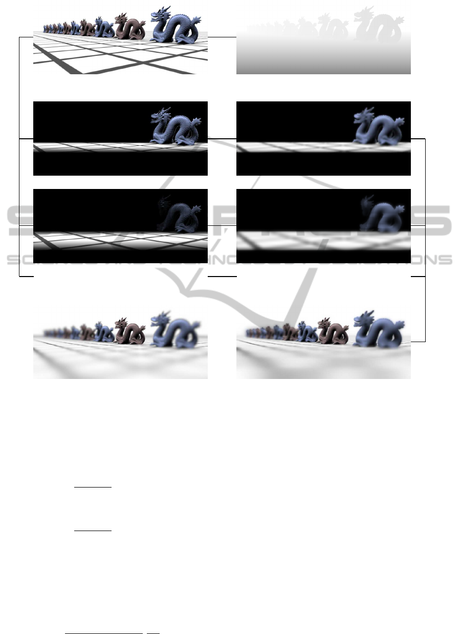
3 DEPTH-OF-FIELD RENDERING
The proposed algorithm decomposes a pinhole im-
age with depth information into sub-images that cor-
respond to certain depth ranges as illustrated in Fig-
ure 1. Similarly to previously published methods
(Barsky et al., 2005; Kraus and Strengert, 2007a), the
algorithm consists of a loop over all sub-images start-
ing with the sub-image corresponding to the farthest
depth range. For each sub-image, the following three
steps are performed:
1. The pinhole image is matted according to the pix-
els’ depth (Figure 1c).
2. The matted sub-image is blurred using the
“opaque image blur” discussed in Section 4 (Fig-
ure 1d).
3. The blurred sub-image is blended over the content
of an (initially cleared) framebuffer, in which the
result is accumulated (Figure 1f).
Note that no disocclusion of pixels is necessary
whereas the disocclusion step in previous published
systems tends to be the most costly computation
(Barsky et al., 2005; Kraus and Strengert, 2007a).
The matting and blending in our prototype is per-
formed as in the system by Kraus and Strengert.
Specifically, we approximate the blur radius r
i
of the
i-th sub-image by:
r
i
def
= 1.7× 2
|i|−1
for i 6= 0 and r
0
def
= 0. (1)
The blur radius is specified in pixels and corresponds
to the radius of the circle of confusion. Thus, the cor-
responding depth z
i
of the i-th sub-image can be com-
GRAPP 2011 - International Conference on Computer Graphics Theory and Applications
154
(a) (b)
- -
- -
- -
... ...
(c) (d)
(e) (f)
Figure 1: Data flow in our method: (a) input pinhole image, (b) input depth map, (c) sub-images after matting, (d) sub-images
after opaque image blur (see Figure 3), (e) ray-traced reference image (Pharr and Humphreys, 2004), (f) blended result of our
method. In (c) and (d) only the opacity-weighted RGB components of the (−1)st sub-image (top) and the (−2)nd sub-image
(bottom) are shown.
puted with the thin lens approximation. The result is:
z
i
def
=
z
focal
1+ r
i
/r
∞
for i < 0, (2)
z
0
def
= z
focal
, (3)
z
i
def
=
z
focal
1− r
i
/r
∞
for i > 0. (4)
Here, z
focal
is the depth of the focal plane and r
∞
is
the blur radius of infinitely distant points. r
∞
can be
expressed in terms of the focal length f, the f-number
N, the field-of-view angle in y direction γ
fovy
, and the
height of the image h
pix
in pixels:
r
∞
def
=
h
pix
2z
focal
tan
γ
fovy
/2
f
2N
. (5)
The depths z
i−2
, z
i−1
, z
i
, and z
i+1
of four sub-images
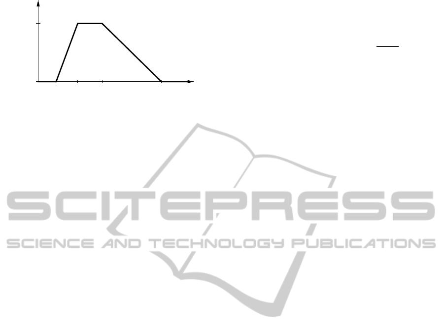
are used to define the matting functions ω
i
(z) for pix-
els of the i-th sub-image as illustrated in Figure 2.
However, the weighting functions for the foremost
and backmost sub-images are adjusted to remove the
ramps at the extremes; i.e., the weight is set to 1 where
there is no other sub-image that would include a pixel.
The matting of the i-th sub-image is then per-
formed in a fragment shader by looking up the depth z
of each pixel, evaluating the weighting function ω
i
(z)
and multiplying it to the RGBA color of the pinhole
image, where the opacity A of the pinhole image is
set to 1.
After matting, each sub-image is blurred as de-
scribed in Section 4. The resulting blurred colors
RGBA
sub
of the sub-image are then blended with the
USING OPAQUE IMAGE BLUR FOR REAL-TIME DEPTH-OF-FIELD RENDERING
155
Ω
i
HzL
0
1
z
i-2
z
i-1
z
i
z
i+1
z
Figure 2: Illustration of the matting function ω
i
(z) for the
i-th sub-image based on the depths z
i−2
to z
i+1
.
colors RGB
buf
of a color buffer, which is initially set
to black. The blending employs the “over” opera-
tor for pre-multiplied (i.e., opacity-weighted) colors
(Porter and Duff, 1984) since the sub-images are pro-
cessed from back to front:
RGB
buf
← RGB
sub
+ (1− A
sub
) × RGB
buf
. (6)
After the frontmost sub-image has been processed,
the colors RGB
buf
represent the resulting image with
the computed depth-of-field effect.
While this algorithm is significantly less complex
than previously published algorithms for sub-image
processing (Barsky et al., 2005; Kraus and Strengert,
2007a), it strongly depends on an image blur that does
not disocclude pixels, i.e., the image blur must not
decrease the opacity of any pixel. The next section
describes such a filter.
4 OPAQUE IMAGE BLUR
The proposed “opaque image blur” of sub-images
guarantees not to disocclude pixels in order to avoid
rendering artifacts that are caused by partial occlu-
sions, which are most visible at silhouettes of objects
in sub-images (Barsky et al., 2005). This is achieved
by only increasing the opacity of pixels as described
in this section.
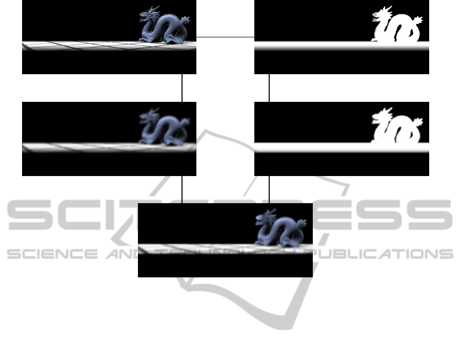
The opaque blur of an RGBA image consists of
three steps, which are illustrated in Figure 3.
1. A glow filter (James and O’Rorke, 2004) is ap-
plied to the A channel of the RGBA image (Fig-
ures 3b and 3d). This glow filter must not decrease
the A channel of any pixel. The result is called
A
glow
.
2. A standard blur filter is applied to all channels
of the original RGBA image (Figures 3a and 3c).
The result is called RGBA
blur
.
3. The opacity of the blurred image is replaced
by the opacity computed by the glow filter
(Figure 3e). To this end, the blurred colors
are rescaled since they are considered opacity-
weighted colors. The result is called RGBA
sub
:
RGBA
sub
def
= RGBA
blur
×
A
glow
A
blur
(7)
For each sub-image of the algorithm described
in Section 3, the result RGBA
sub
is then used in
Equation 6.
Without the color rescaling, the increased opacity
A
glow
would result in dark silhouettes around objects
of full opacity. To avoid artifacts, the range of the
glow filter should not be larger than the range of the
blur filter. Otherwise, the color rescaling is likely to
increase colors that are unrelated to the objects that
caused the increased opacity.
While any non-decreasing glow filter and any
standard blur filter can be used to implement an
opaque image blur, we propose to employ pyramid
algorithms for both filters because of their favorable
performance on GPUs. Moreover, pyramid versions
of the glow filter and the blur filter can share a com-
mon analysis phase, which reduces the total compu-
tational costs by about one quarter.
For the standard blur we employ a pyramidal blur
(Strengert et al., 2006) with a 4× 4 box analysis filter
(Kraus and Strengert, 2007b). The analysis phase of
this pyramidal blur corresponds to a mipmap gener-
ation; however, the number of required levels is lim-
ited by the strength of the blur. For the algorithm dis-
cussed in Section 3, |i| levels of the image pyramid
have to be computed for the i-th sub-image. The syn-
thesis phase of the pyramidal blur iteratively expands
the i-th pyramid level to the original size with a syn-
thesis filter that corresponds to a biquadratic B-spline
interpolation (Strengert et al., 2006).
The glow filter makes use of the opacity A
ana
of
the exact same analysis pyramid as the pyramidal
blur. However, the synthesis is modified in order to
guarantee that the opacity of no pixel is decreased.
This is achieved by multiplying the transparency of
each expanded level, i.e., 1 − A
exp
, with the trans-
parency of the corresponding analysis level of the
same size, i.e., 1 − A
ana
. The resulting transparency
determines the opacity A
syn
of the new synthesis level
for the pyramidal glow:
A
syn
def
= 1− (1− A
exp
)(1− A
ana
) (8)
= A
exp
+ A
ana
− A
exp
A
ana
. (9)
It is straightforward to implement this blending in a
fragment shader.
After both pyramid algorithms have been per-
formed, the blurred colors have to be rescaled to
the opacity computed by the glow filter as discussed
GRAPP 2011 - International Conference on Computer Graphics Theory and Applications
156
-
A channel
(a) (b)
?
blur
?
glow
(c) (d)
? ?
rescaling of colors
(e)
Figure 3: Data flow in the opaque image blur: (a) input RGBA image (only RGB is shown), (b) opacity (i.e., A channel) of
the input image visualized as gray-scale image, (c) standard blur filter applied to the input RGBA image (A is not shown),
(d) glow filter applied to the opacity of the input image, (e) resulting opaque image blur.
above. For efficiency, this step should be combined
with the final synthesis step of the pyramidal blur and
the final synthesis step of the pyramidal glow. Since
the final synthesis steps expand the image to the full
size of the input image, it is particularly beneficial to
implement these steps as efficiently as possible.
5 RESULTS
Figure 4 compares two images generated by our
method with ray-traced images computed with
pbrt (Pharr and Humphreys, 2004) and images
produced by the method proposed by Kraus and
Strengert. Obviously, our method avoids any disoc-
clusion which results in too opaque objects. On the
other hand, color bleeding between objects at differ-
ent depths is still avoided. Due to the nonlinear glow,
the silhouettes of objects are too sharp in our method.
This is, however, a consequence of the particular glow
filter employed in this work. We assume that there
are alternative glow filters that produce better visual
results.
Our method performed 1.9× faster than the
method by Kraus and Strengert on a 13” MacBook
Pro with an NVIDIA GeForce 320M, i.e., almost
twice as fast. While our implementation of both meth-
ods was not optimized and includes some copy op-
erations that could be avoided, we don’t see many
possibilities to optimize the disocclusion part of the
method by Kraus and Strengert; therefore, it is un-
likely that we overestimate the improvement gained
by avoiding the disocclusion.
The implementation also revealed an interesting
side effect of our method: artifacts at the boundaries
of the view port are effectively avoided by the opaque
image blur if there is a border of transparent black
pixels. In particular, a border width of one pixel
is sufficient. In contrast, the system by Kraus and
Strengert requires an embedding of the view port in a
larger framebuffer and relies on extrapolation to gen-
erate pixel data that provides continuous blurring at
the boundaries of the original view port.
USING OPAQUE IMAGE BLUR FOR REAL-TIME DEPTH-OF-FIELD RENDERING
157
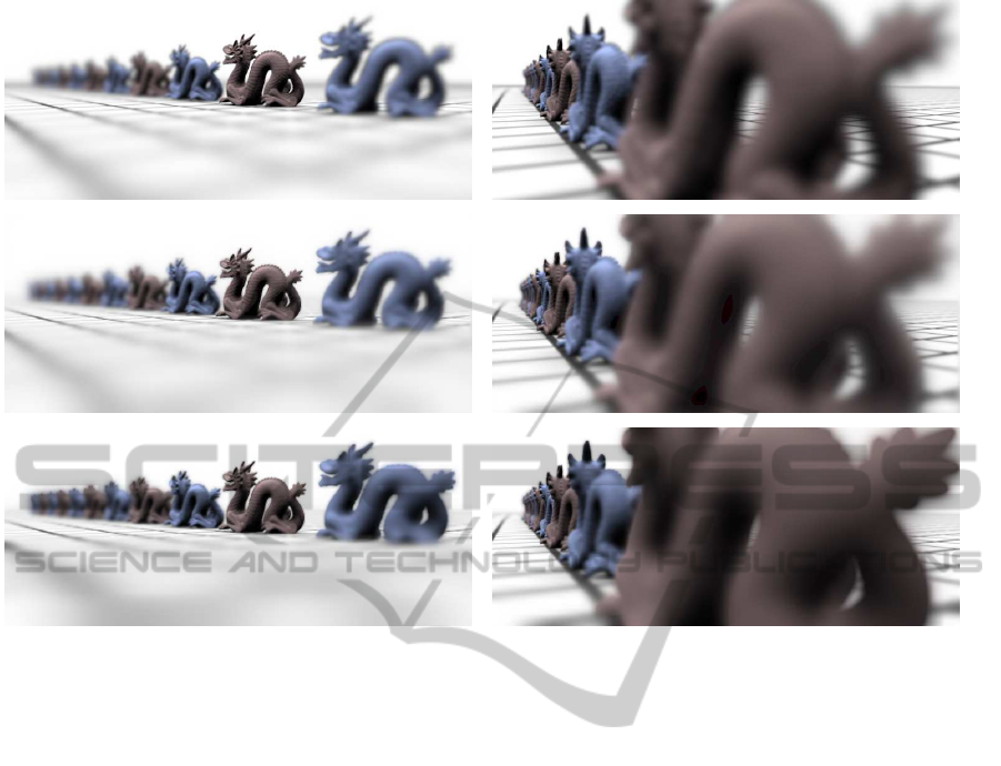
Figure 4: Comparison of renderings with depth of field generated by
pbrt
(Pharr and Humphreys, 2004) (top row), the method
published by Kraus and Strengert (middle row), and the proposed method (bottom row).
6 CONCLUSIONS
The performance of the presented algorithm is inde-
pendent of the scene complexity and independent of
the rendering of the pinhole image. It offers a sig-
nificantly improved performance in comparison to al-
gorithms based on the blurring of sub-image (Barsky
et al., 2005; Kraus and Strengert, 2007a) as it avoids
the costly computations required by disocclusions of
pixels. Moreover, our algorithm is easier to imple-
ment since algorithms for the disocclusion of pixels
tend to be rather complex. On the other hand, the per-
formance of our method is worse than methods based
on computing differently blurred versions of a pinhole
image (Hammon, 2007; Lee et al., 2009b).
The image quality achieved by the proposed algo-
rithm is also between these two approaches: it avoids
artifacts such as color bleeding between objects of
different depths, which often occur in methods that
do not use sub-images (Hammon, 2007; Lee et al.,
2009b). On the other hand, the image quality is re-
duced in comparison to other approaches based on
sub-images (Barsky et al., 2005; Kraus and Strengert,
2007a) because of the missing disocclusions and the
particular opaque image blur.
In summary, we propose a new depth-of-field ren-
dering algorithm with a unique trade-off between per-
formance and image quality. Maybe even more im-
portantly, this work demonstrates a new technique
to handle disocclusions in depth-of-field rendering.
To this end, an “opaque image blur” has been pro-
posed, which might find further applications apart
from depth of field as discussed in the next section.
7 FUTURE WORK
Future work includes research on alternative glow fil-
ters for the opaque image blur described in Section 4.
Of particular interest are glow filters that result in con-
vincing depth-of-field effects.
Further potential applications of the opaque image
blur include the application of motion blur and gen-
eralized depth-of-field effects (Kosloff and Barsky,
2007) to arbitrary parts of bitmap images. In these
cases, some parts of an image have to be blurred
without any information about the disoccluded pixels.
Since the opaque image blur avoids the disocclusion
of pixels, it offers an extremely efficient alternative to
more costly disocclusion techniques.
GRAPP 2011 - International Conference on Computer Graphics Theory and Applications
158

REFERENCES
Barsky, B. A. (2004). Vision-realistic rendering: Simulation
of the scanned foveal image from wavefront data of
human subjects. In APGV ’04: Proceedings of the
1st Symposium on Applied Perception in Graphics and
Visualization, pages 73–81.
Barsky, B. A., Tobias, M. J., Chu, D. P., and Horn, D. R.
(2005). Elimination of artifacts due to occlusion and
discretization problems in image space blurring tech-
niques. Graphical Models, 67(6):584–599.
Cook, R. L., Carpenter, L., and Catmull, E. (1987). The
reyes image rendering architecture. In SIGGRAPH
’87: Proceedings of the 14th Annual Conference on
Computer Graphics and Interactive Techniques, pages
95–102.
Cook, R. L., Porter, T., and Carpenter, L. (1984). Dis-
tributed ray tracing. In SIGGRAPH ’84: Proceedings
of the 11th Annual Conference on Computer Graphics
and Interactive Techniques, pages 137–145.
Demers, J. (2004). Depth of field: A survey of techniques.
In Fernando, R., editor, GPU Gems, pages 375–390.
Addison Wesley.
Haeberli, P. and Akeley, K. (1990). The accumulation
buffer: hardware support for high-quality rendering.
In SIGGRAPH ’90: Proceedings of the 17th an-
nual conference on Computer graphics and interac-
tive techniques, pages 309–318. ACM.
Hammon, E. (2007). Practical post-process depth of field.
In Nguyen, H., editor, GPU Gems 3, pages 583–606.
Addison Wesley.
James, G. and O’Rorke, J. (2004). Real-time glow. In Fer-
nando, R., editor, GPU Gems, pages 343–362. Addi-
son Wesley.
Kolb, C., Mitchell, D., and Hanrahan, P. (1995). A realistic
camera model for computer graphics. In SIGGRAPH
’95: Proceedings of the 22nd annual conference on
Computer graphics and interactive techniques, pages
317–324. ACM.
Kosloff, T. J. and Barsky, B. A. (2007). An algorithm
for rendering generalized depth of field effects based
on simulated heat diffusion. In ICCSA’07: Proceed-
ings of the 2007 international conference on Com-
putational science and its applications, pages 1124–
1140.
Kosloff, T. J., Tao, M. W., and Barsky, B. A. (2009).
Depth of field postprocessing for layered scenes us-
ing constant-time rectangle spreading. In Proceedings
of Graphics Interface 2009, GI ’09, pages 39–46.
Kraus, M. and Strengert, M. (2007a). Depth-of-field ren-
dering by pyramidal image processing. Computer
Graphics forum (Proceedings Eurographics 2007),
26(3):645–654.
Kraus, M. and Strengert, M. (2007b). Pyramid filters based
on bilinear interpolation. In Proceedings GRAPP
2007 (Volume GM/R), pages 21–28.
Kˇriv´anek, J.,
ˇ
Z´ara, J., and Bouatouch, K. (2003). Fast depth
of field rendering with surface splatting. In Proceed-
ings of Computer Graphics International 2003, pages
196–201.
Lee, S., Eisemann, E., and Seidel, H.-P. (2009a). Depth-of-
field rendering with multiview synthesis. ACM Trans-
actions on Graphics (Proc. ACM SIGGRAPH ASIA),
28(5):1–6.
Lee, S., Eisemann, E., and Seidel, H.-P. (2010). Real-
time lens blur effects and focus control. ACM Trans-
actions on Graphics (Proc. ACM SIGGRAPH’10),
29(4):65:1–7.
Lee, S., Kim, G. J., and Choi, S. (2008). Real-time depth-
of-field rendering using splatting on per-pixel lay-
ers. Computer Graphics Forum (Proc. Pacific Graph-
ics’08), 27(7):1955–1962.
Lee, S., Kim, G. J., and Choi, S. (2009b). Real-time
depth-of-field rendering using anisotropically filtered
mipmap interpolation. IEEE Transactions on Visual-
ization and Computer Graphics, 15(3):453–464.
Pharr, M. and Humphreys, G. (2004). Physically Based
Rendering: From Theory to Implementation. Morgan
Kaufmann Publishers Inc.
Porter, T. and Duff, T. (1984). Compositing digital im-
ages. In SIGGRAPH ’84: Proceedings of the 11th
annual conference on Computer graphics and inter-
active techniques, pages 253–259. ACM.
Potmesil, M. and Chakravarty, I. (1982). Synthetic im-
age generation with a lens and aperture camera model.
ACM Trans. Graph., 1(2):85–108.
Rokita, P. (1993). Fast generation of depth of field ef-
fects in computer graphics. Computers & Graphics,
17(5):593–595.
Scofield, C. (1992). 2 1/2-d depth-of-field simulation for
computer animation. In Graphics Gems III, pages 36–
38. Academic Press Professional.
Shinya, M. (1994). Post-filtering for depth of field simu-
lation with ray distribution buffer. In Proceedings of
Graphics Interface ’94, pages 59–66.
Sternberg, S. (1986). Grayscale morphology. Computer
Vision, Graphics, and Image Processing, 35(3):333–
355.
Strengert, M., Kraus, M., and Ertl, T. (2006). Pyramid
methods in GPU-based image processing. In Proceed-
ings Vision, Modeling, and Visualization 2006, pages
169–176.
USING OPAQUE IMAGE BLUR FOR REAL-TIME DEPTH-OF-FIELD RENDERING
159
