
HAND GESTURE RECOGNITION THROUGH ON-LINE
SKELETONIZATION
Application of Continuous Skeleton to Real-time Shape Analysis
Alexey Kurakin
Moscow Institute of Physics and Technology, Moscow, Russian Federation
Leonid Mestetskiy
Moscow State University, Moscow, Russian Federation
Keywords:
Continuous skeleton, Shape analysis, Feature extraction, Gesture recognition, Hand tracking, Computer vi-
sion.
Abstract:
New method for palm shape analysis and hand gesture recognition with help of continuous skeletons is pre-
sented in the paper. Continuous skeleton makes possible to develop fast and simple methods for palm shape
analysis and measure a lot of its features. In particular it is possible to develop efficient methods for segmenta-
tion and analysis of the object topological structure, measuring relative location of object parts and measuring
width of the object in arbitrary place. Applying to palm shape analysis skeleton provides a way to determine
number of visible fingers, estimate their thickness and location, and perform efficient palm shape comparison
with the sample. Moreover proposed approach allows measuring all mentioned features regardless of palm
orientation in the frame. And efficient algorithms for skeleton construction allow performing shape analysis
with high speed in real-time applications.
1 INTRODUCTION
At the present time gesture recognition problem is
subjected to active research due to its practical im-
portance. Potential applications of gesture recogni-
tion technologies include human-computer interac-
tion (Dhawale et al., 2006), virtual reality applica-
tions (Aguiar et al., 2009), sign language recognition
(Burger et al., 2007) and other (Mitra and Acharya,
2007; Garg et al., 2009).
A lot of different approaches for hand gesture
recognition exist. Some of these methods require sev-
eral cameras or special equipment (Schlattman and
Klein, 2007; Wang and Popovi´c, 2009). There are
methods which maximize the likelihood of hand to
be in certain pose by input image (Liu et al., 2008),
but such methods are computationally expensive. An-
other group of methods work in real-time without spe-
cial equipment (Burger et al., 2007; Dhawale et al.,
2006). However, the range of possible configurations
of hand that can be successfully detected with such
methods is limited due to scarce feature extraction
mechanism.
In this paper application of continuous skeleton
to real-time hand shape analysis is presented. Sim-
ilar approach was used in (Mestetskiy, 2007) for
shape comparison of flexible objects. Palm silhou-
ette boundary is approximated as a polygon, and its
skeleton is constructed with help of Voronoi diagram
of line segments. Simple and efficient pruning algo-
rithm helps to get rid of unimportant skeleton edges.
Hand silhouette skeletonization provides rich fea-
ture generation mechanism and allows performing
complex shape analysis, determining topology of the
hand (number and shape of visible fingers), estimat-
ing relative location of palm parts and measuring
width of silhouette in arbitrary place. Moreover such
analysis can be performed regardless of palm orien-
tation in the frame. In addition computationally effi-
cient skeletonization and pruning algorithms are suit-
able for usage in real-time applications.
The text of the paper is organized in a following
way. Review of the literature on the topic is given in
Section 2. The notion of the continuous skeleton is
given in Section 3. Application of skeleton analysis
for palm shape recognition is presented in Section 4.
Experiments are described in Section 5. And Section
6 completes the paper and states the conclusions of
555
Kurakin A. and Mestetskiy L..
HAND GESTURE RECOGNITION THROUGH ON-LINE SKELETONIZATION - Application of Continuous Skeleton to Real-time Shape Analysis.
DOI: 10.5220/0003315505550560
In Proceedings of the International Conference on Computer Vision Theory and Applications (VISAPP-2011), pages 555-560
ISBN: 978-989-8425-47-8
Copyright
c
2011 SCITEPRESS (Science and Technology Publications, Lda.)

the research and future works.
This work is supported by the Russian Foundation
of Basic Researches (grant 08-01-00670).
2 RELATED WORK
The topic of gesture recognition is subjected to ac-
tive research, and a lot of different approaches to the
problem exist. Some of them are not widely used
due to requirement of complex experimental setup
(Schlattman and Klein, 2007) or expensiveequipment
such as instrumented gloves (Aguiar et al., 2009).
Among more available techniques color markers
could be used for hand tracking and gesture recogni-
tion. And there are a lot of methods which use only
image of hand obtained from the camera. Good re-
view of vision based method is presented in paper
(Garg et al., 2009).
In (Wang and Popovi´c, 2009) special colored
glove is used for hand pose estimation. The advan-
tage of this approach is high range of successfully es-
timated poses. Shortcomings include requirement to
wear the glove and increased requirement to the im-
age quality. Also pose estimation involved computa-
tionally expensive search in the database of available
poses, that’s why parallel algorithm shows only 10fps
on modern computer.
In papers similar to (Liu et al., 2008) hand pose
estimation is performed by the search in multidimen-
sional space of all possible hand configurations. How-
ever such approaches are computationally expensive
and can hardly be used in real-time applications.
Also bare hand tracking could be performed by
preliminary segmenting skin and non-skin regions in
the image and further analysis of regions correspond-
ing to hand. For example, in papers (Burger et al.,
2007) and (Dhawale et al., 2006) macro features (such
as size, position and Hu invariants) of palm silhouette
are used for hand gesture recognition. These methods
work fast but the set of detected gestures is poor and
the methods provide no way to evaluate location of
fingers.
The most promising approach to shape analysis
is computation and analysis of skeleton of palm sil-
houette. In particular such approach is described in
(Beristain and Grana, 2010). In that paper skeleton
of palm silhouette is constructed and simple greedy
algorithm for skeleton comparison is used to classify
hand gestures into 3 classes. But the paper did not
cover finger detection and tracking as well as mea-
surement of different silhouette features. In addition
their skeletonization algorithm operates with discrete
boundary and requires development of complex prun-
ing methods given the fact that such methods not al-
ways provide acceptable result.
3 CONTINUOUS SKELETON
Methods considered in the paper are based on the no-
tion of the skeleton of a figure. The skeleton is a set of
points which are equidistant from two or more figure
borders.
In the literature there are two approaches of de-
scribing and constructing a skeleton: discrete and
continuous approaches. In the discrete case skele-
ton is described as the set of pixels, and it is con-
structed with help of pixel-based processing of the
original image. In the continuous case skeleton is de-
scribed as a union of points and curves. The advan-
tage of continuous approach is the fact that it is easier
to perform further processing on continuous skeleton
in comparison to discrete one. In this paper contin-
uous approach is used and all necessary definitions
are given below. Details about continuous skeletons
and the process of skeletonization could be found in
(Mestetskiy, 2010), (Mestetskiy and Semenov, 2008)
and (Siddiqi and Pizer, 2008).
Maximum inscribed circle is the closed circle C
that is completely lying inside the figure F, and any
other circle C
′
within the figure does not contain C:
∀C
′
⊂ F,C
′
6= C :C 6⊂ C
′
.
Skeleton of polygonal shape is the locus of cen-
ters of maximum inscribed circles. Also radius
of inscribed circle is associated with each point of
the skeleton, and such association between skeleton
points and radii is called radial function.
It can be proved that the skeleton of the polygon
consists of finite set of line segments and arcs of the
parabolas (Mestetskiy, 2010). So the skeleton could
be considered as a planar graph. And such skeleton
representation is called axial graph. Below in the ar-
ticle we use both graph and curve properties of skele-
ton, so terms axial graph and skeleton will be used
interchangeably.
Degrees of vertices in axial graph can be from 0 to
3. Each edge of this graph can be line segment or arc
of the parabola. Radius of maximum inscribed circle
is associated with each vertex of the graph and any
internal point of the edges.
The process of skeleton construction from binary
image is showed on the figure 1. Low resolution im-
age is chosen as an example: palm size is 36 pixels
and fingers’ widths are about 5-6 pixels. Continuous
skeleton construction from binary image is described
in details in the book (Mestetskiy, 2009), but briefly
algorithm consists of the following steps:
VISAPP 2011 - International Conference on Computer Vision Theory and Applications
556
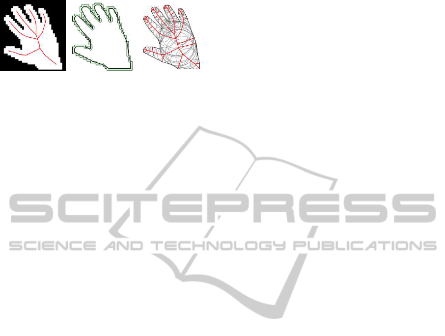
Figure 1: The process of skeleton construction. Left. Source
binary image and resultant skeleton. Middle. Boundary cor-
ridor and minimal perimeter polygon. Right. Skeleton be-
fore pruning.
1. Construction of Boundary Corridor of the Bi-
nary Image. For initial binary image (figure
1, left) boundary corridor is calculated based on
boundary tracing. Boundary corridor consists
of two sequences of pixels: black sequence and
white sequence. White sequence corresponds to
internal boundary of the corridor and black to ex-
ternal. On the middle part of the figure 1 corridor
is drawn in gray color.
2. Construction of Minimal Perimeter Polygon
Inside the Boundary Corridor. Closed path
of minimal perimeter is constructed inside the
boundary corridor. Such path will be closed con-
tour without self-intersections. Physical model
of the path is a rubber thread stretched along the
boundary corridor. Minimal perimeter polygon is
shown on the middle part of fig. 1.
3. Skeleton Construction. Skeleton is constructed
for the minimal perimeter polygon. On the right
part of the figure 1 skeleton and maximum in-
scribed circles at the vertices of the axial graph
are drawn.
4. Skeleton Regularization. When skeleton is con-
structed it is subjected to pruning. Pruning is
performed by sequential cutting of certain ter-
minal edges of the skeleton. Cutting criteria is
based upon the following principle. Initial poly-
gon could be represented as a union of all in-
scribed circles with the centers at the skeleton
points. When skeleton edge is removed associated
circles are removed too. Union of the remaining
circles forms a figure which is called silhouette
of the remaining skeleton part. This silhouette is
a subset of the initial polygon and it is situated
inside it. If Hausdorff distance of this silhouette
and initial polygon is less than the threshold then
skeleton edge is cut, otherwise - not. In the exam-
ple on the figure 1 threshold is equal to 2 pixels.
In the rest of the article by skeleton we mean
pruned skeleton. Moreover due to the fact that
parabolic edges are usually short, they are approxi-
mately treated as line segments.
In the axial graph length of each edge is deter-
mined as Euclidean length of the correspondingskele-
ton segment. Lengths of the edges naturally generate
distance on the axial graph, in such a way that dis-
tance between two vertices can be calculated as the
total length of the edges in the shortest path between
these vertices.
4 PALM SHAPE ANALYSIS
4.1 Skeleton Branch and its Properties
Here we introduce the notion of skeleton branch
which is a part of skeleton treated as a continuous
curve.
Consider a continuous piecewise-smooth curve
without self-intersections~s(•) : s(l) = {x(l), y(l)},l ∈
[0,L], and let l be natural parameter of the curve (i.e.
arc length along the curve). Let each point of the
curve ~s(•) be a point of the skeleton. In such case
we will call the curve~s(•) as skeleton branch, which
connects points r(0) and r(L) of the skeleton
Radial function R(x,y) is known for each point P
of the skeleton, and its value is equal to the radius of
maximum inscribed circle with the center at point P.
Let’s define radial function along the branch~s(•) as
R
s
(l) = R(~s(l)),l ∈ [0, L].
Theorem. For any skeleton branch ~s(•) of the
skeleton of polygonal shape radial function along the
segment R
s
(l) is continuous and piecewise smooth
function.
The proof of the theorem is based on the fact
that the skeleton of polygonal shape is union of finite
number of line segments and arcs of parabolas, and
radial function R(x, y) along each such piece of the
skeleton is linear or quadratic function of coordinates
(Mestetskiy, 2010). So if we consider union of such
segments and consider natural parametrization along
them, value of radial function will be smooth along
each segment and continuous at the junctions of seg-
ments.
4.2 Linear Approximation of the Radial
Function
It is inconvenient to work numerically with values of
radial function along the branch due to presence of
parabolic arcs in the skeleton. So we replace the ini-
tial skeleton to its approximation without parabolic
arcs.
Let’s replace all parabolic arcs in the initial skele-
ton by line segments and call the new graph as lin-
early approximated skeleton.
HAND GESTURE RECOGNITION THROUGH ON-LINE SKELETONIZATION - Application of Continuous Skeleton
to Real-time Shape Analysis
557
For each point of linearly approximated skeleton
let’s introduce linearly approximated radial function
˜
R(x,y) in the following way.
˜
R(x,y) is equal to R(x,y)
for the vertices of the initial skeleton, and inside the
edges of approximated skeleton
˜
R(x,y) changes lin-
early from one end of the edge to another.
Similarly to the source skeleton, let’s consider
skeleton branches and approximated radial function
along the branch
˜
R
s
(x,y) for the approximated skele-
ton. It can be proven that such approximated radial
function is continuous and piecewise linear function
of its parameter.
4.3 Calculation of Approximated Radial
Function
Let’s consider two vertices A and B of the initial skele-
ton and simple path P in the axial graph between these
vertices. Path P uniquely defines skeleton branch~s(•)
and approximated skeleton branch ˜s(•). Approxi-
mated radial function along the branch ˜s(•) could be
easily calculated in the following way.
Denote vertices in the path P as V
0
=
A,V
1
,...,V
n−1
,V
n
= B.
Denote the values of the radial function in these
vertices as R(V
i
) = R
i
.
Let L
i
be the length along the graph between ver-
tices A and V
i
, that is L
i
=
∑
i−1
k=0
|V
k
V
k+1
|
In such notion approximated radial function along
segment
˜
R
˜s
(l) could be calculated as:
˜
R
˜s
(l) =
R
i
l = L
i
;
αR
i
+ (1− α)R
i+1
l = αL
i
+ (1− α)L
i+1
,
α ∈ (0,1)
4.4 Fingers Detection
Fingers detection is performed by analysis of skeleton
branches which ends in the dangling vertices. The
algorithm is described below.
Let A be an arbitrary dangling vertex of the axial
graph. Let B be the nearest (in terms of the distance
along the graph) to the A vertex of the axial graph
which degree is equal to 3.
Consider approximated skeleton branch ˜s(•) gen-
erated by the shortest path P between vertices A and
B, and consider approximated radial function
˜
R
˜s
(l)
along the branch ˜s(•).
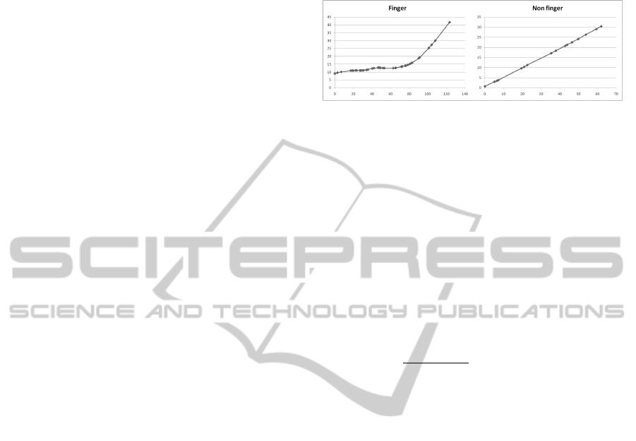
Samples of the function
˜
R
˜s
(l) for two different
skeleton branches of palm silhouette from left part
of figure 3 are shown on figure 2. Left part of fig-
ure 2 depicts
˜
R
˜s
(l) for skeleton branch corresponding
to finger, and the right plot corresponds to non-finger
skeleton branch which starts from dangling vertex in
the bottom part of the palm.
Figure 2: Radial function for finger and non finger.
As it can be seen from the plots, there are distinc-
tive features associated with the length of the segment
and radial function values which can be used to dis-
tinguish segments of the axial graph corresponding to
fingers from others. These distinctive features were
used to classify segments of the axial graph as fingers
or non fingers.
Here we use notation from the previous subsec-
tion (V
0
...,V
n
, R
0
...,R
n
and L
0
...,L
n
), and intro-
duce values D
i
which are discrete derivatives of R
i
by
L
i
. In the corner points let D
0
= 0, D
n
= +∞, and in
the rest points let D
i
be calculated by the formula:
D
i
=
R
i+1
− R
i−1
L
i+1
− L
i−1
, i = 1,...,n− 1
We use R
i
, L
i
and D
i
to estimate the position of
point C - point of articulation of finger and metacar-
pus. Given point C different features of the skeleton
branch, such as length, average width, distance to the
center of the palm, could be measured. And all these
values are used for fingers classification.
Search of point C is performed from the assump-
tion that at the end of the finger one of the following
conditions should be satisfied:
• R should increase in 2 - 2.5 times in comparison
with the beginning of the finger
• Radius starts to increase significantly, i.e. discrete
derivatives D
i
are greater than the threshold
When the point C is found for the segment AB,
we calculate length of segments AB and AC as well
as width of segment AC. Width is calculated as the
value of radial function at predefined point of AC or
as average value of the radial function on the AC. We
classify AB as a finger if all the following conditions
are met:
• |AC|/|AB| ≥ 0.35
• Width of AC lies in specified range
• Length of AB should be greater than the threshold,
i.e. finger should not be short
Result of the work of the described algorithm is
shown in the figure 3. Big blue circle is the circle of
VISAPP 2011 - International Conference on Computer Vision Theory and Applications
558
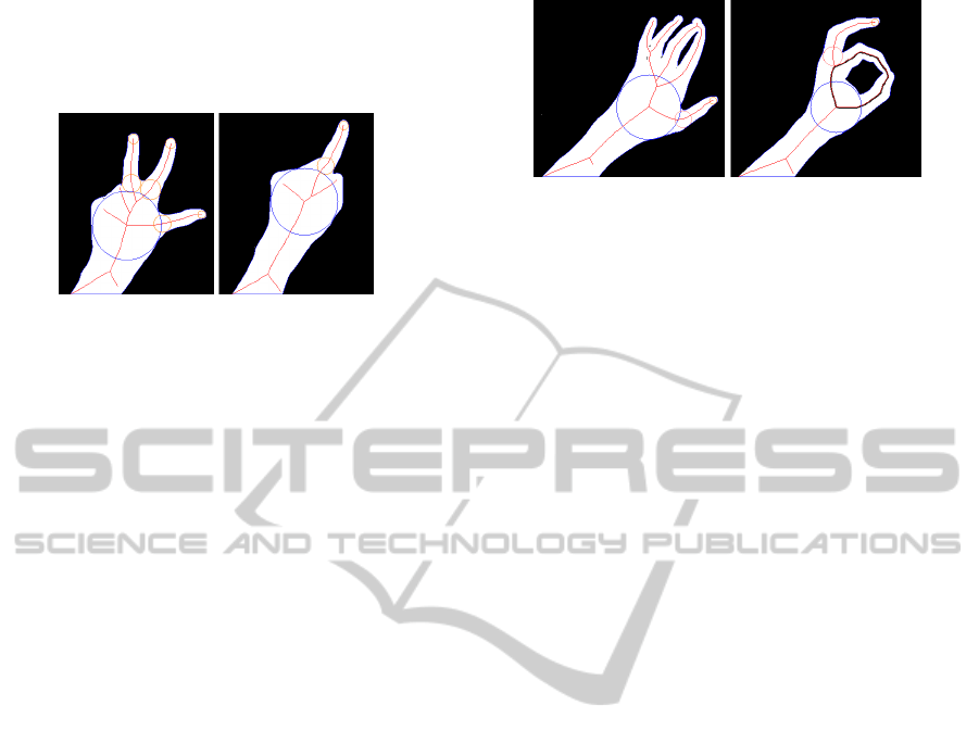
maximal radius inscribed in the palm. The center of
this circle is considered as palm center. And small or-
ange circles correspond to fingertips and articulations
of fingers and metacarpus.
Figure 3: Fingers detection samples.
4.5 Gesture Recognition
Gesture recognition is performed by calculating rela-
tive movement of fingers and the palm, and by calcu-
lating absolute movement of the palm as a whole. Us-
ing these values several gestures are recognized and
used in the demo-software. The list of the gestures is
following:
• One finger is seen (fig. 3, right). The finger and
the palm are moving as a whole. This gesture is
used for cursor movement and object dragging in
the demo.
• Two fingers are seen, and their fingertips are mov-
ing along the straight line (fig. 5). This gesture is
used for object zooming.
• Three fingers are seen and form a triangle with
approximately constant lengths of the sides (fig.
3, left). This gesture is used for object rotation.
• Big and pointing fingers form a ring for a short
period of time (fig. 4, right). This gesture is used
for object grabbing.
• All five fingers are seen and spread wide apart for
a short period of time (fig. 1). This gesture is used
for object releasing.
Gestures with 1,2,3 and 5 fingers are detected eas-
ily with help of the algorithm from subsection 4.4.
Circles with the centers in the dangling vertices of
skeleton branches corresponding to fingers are treated
as fingertip positions. These circles along with de-
tected junction points of fingers and metacarpus are
drawn orange in figure 3.
Metacarpus movement detection and palm scale
measurement is performed using position and radius
of inscribed circle which radius is maximal among all
inscribed circles and center is at the vertex of axial
graph with degree 3. This circle is shown in blue at
the figure 3.
Ring gesture is detected by finding cycles in the
Figure 4: Cycles in skeleton. Cycle on the left corresponds
to non-ring gesture and cycle on the right corresponds to
ring gesture.
axial graph. It should be noted that only cycles which
contain vertices near the center of the palm (blue cir-
cle) are treated as valid cycles (see figure 4), because
only such cycles are formed from ring between big
and pointing fingers. Such classification of cycles is
possible due to the fact that coordinates of each vertex
is known in the axial graph. Moreover to detect ring
gesture, we do not need to analyze contours of palm
silhouette and should only use axial graph.
Five fingers and ring gestures are detected as dy-
namic gestures, that is time when the gesture observed
is measured, and gesture counts only if it has been ob-
served for predefined time interval. Dynamic gesture
recognition is possible due to fast frame processing.
5 EXPERIMENTS
Software system was developed to demonstrate and
evaluate proposed gesture recognition method. This
system allows movement, zoom and rotation of sev-
eral objects on the screen of computer, and all the con-
trol is performed by means of gestures.
The following scheme of experimental setup was
used. Conventional consumer web-cam (Logitech
9000) was situated above the homogenous dark sur-
face.
In order to obtain palm silhouette per-pixel skin
detection is performed on the image obtained from
the web-cam (Vezhnevets et al., 2003; Phung et al.,
2005).
Continuous skeleton is constructed for the ob-
tained palm silhouette. And the skeleton was ana-
lyzed by algorithms described in the section 4. As
a result, gestures mentioned in the subsection 4.5 was
detected and used for object movement, zoom and ro-
tation. Figure 5 shows screen shot of the developed
software.
Effective algorithms for skeleton construction and
pruning make it possible to use the system in real-
time application. For example, single threaded im-
plementation of frame processing (including skin re-
gions segmentation, skeleton construction, pruning,
HAND GESTURE RECOGNITION THROUGH ON-LINE SKELETONIZATION - Application of Continuous Skeleton
to Real-time Shape Analysis
559
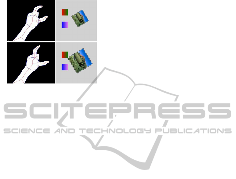
Figure 5: Sample screen shots of the software for experi-
ments. This image demonstrates gesture which was used
for object scaling.
gesture recognition and drawing of the result) takes
about 22 ms per frame on 2.4Ghz Intel Core 2 Quad
CPU, which gives 45fps.
6 CONCLUSIONS
Method of the palm shape analysis by the continu-
ous skeleton is considered in the paper. This method
allows wide range of palm silhouette features to be
measured, which is hard or even impossible to mea-
sure with other approaches. Moreover high process-
ing speed makes this method suitable for real-time ap-
plications.
We are going to extend considered approach by
adding the second camera to the setup. Image ob-
tained from the second camera will be subjected to
similar processing, and obtain pairs of coordinates of
each finger will be used for calculation of 3d positions
of hand and fingers. For occlusion handling and esti-
mation of exact hand pose we are going to use hand
model.
In addition, we are going to apply the method
for development of convenient and fast systems for
human-computer interaction and virtual reality appli-
cations (Aguiar et al., 2009).
REFERENCES
Aguiar, R., Pereira, J. M., and Braz, J. (2009). Gadevi -
game development integrating tracking and visualiza-
tion devices into virtools. In GRAPP 2009: Proc. of
4
th
Int. Conf. on Computer Graphics Theory and Ap-
plications, pages 313–321. INSTICC Press.
Beristain, A. and Grana, M. (2010). A stable skeletonization
for tabletop gesture recognition. In Computational
Science and Its Applications ICCSA 2010, volume
6016 of Lecture Notes in Computer Science, pages
610–621. Springer Berlin / Heidelberg.
Burger, T., Urankar, A., Aran, O., Akarun, L., and Caplier,
A. (2007). Cued speech hand shape recognition - be-
lief functions as a formalism to fuse svms and expert
systems. In VISAPP 2007: Proc. of 2
nd
Int. Conf. on
Computer Vision Theory and Applications, volume 2,
pages 5–12. INSTICC Press.
Dhawale, P., Masoodian, M., and Rogers, B. (2006). Bare-
hand 3d gesture input to interactive systems. In
CHINZ ’06: Proc. of the 7th ACM SIGCHI New
Zealand chapter’s int. conf. on Computer-human in-
teraction, pages 25–32, New York, NY, USA. ACM.
Garg, P., Aggarwal, N., and Sofat, S. (2009). Vision based
hand gesture recognition. World Academy of Science
Engineering and Technology, pages 972–977.
Liu, T., Liang, W., and Jia, Y. (2008). 3d articulated hand
tracking by nonparametric belief propagation on fea-
sible configuration space. In VISAPP 2008: Proc. of
3
rd
Int. Conf. on Computer Vision Theory and Appli-
cations, volume 2, pages 508–513. INSTICC Press.
Mestetskiy, L. (2007). Shape comparison of flexible ob-
jects - similarity of palm silhouettes. In VISAPP
2007: Proc. of 2
nd
Int. Conf. on Computer Vision The-
ory and Applications, volume 1, pages 390–393. IN-
STICC Press.
Mestetskiy, L. (2009). Continuous morphology of binary
images: figures, skeletons, circulars. Moscow: Fiz-
matlit (in Russian).
Mestetskiy, L. (2010). Skeleton representation based on
compound bezier curves. In VISAPP 2010: Proc. of
5
th
Int. Conf. on Computer Vision Theory and Appli-
cations, volume 1, pages 44–51. INSTICC Press.
Mestetskiy, L. and Semenov, A. (2008). Binary image
skeleton - continuous approach. In VISAPP 2008:
Proc. of 3
rd
Int. Conf. on Computer Vision Theory and
Applications, volume 1, pages 251–258. INSTICC
Press.
Mitra, S. and Acharya, T. (2007). Gesture recognition: A
survey. IEEE Transactions on Systems, Man and Cy-
bernetics - Part C, 37(3):311–324.
Phung, S. L., Bouzerdoum, A., and Chai, D. (2005). Skin
segmentation using color pixel classification: Analy-
sis and comparison. IEEE Trans. Pattern Anal. Mach.
Intell., 27(1):148–154.
Schlattman, M. and Klein, R. (2007). Simultaneous 4 ges-
tures 6 dof real-time two-hand tracking without any
markers. In VRST ’07: Proceedings of the 2007 ACM
symposium on Virtual reality software and technology,
pages 39–42, New York, NY, USA. ACM.
Siddiqi, K. and Pizer, S. (2008). Medial Representations:
Mathematics, Algorithms and Applications. Springer
Publishing Company, Incorporated, 1st edition.
Vezhnevets, V., Sazonov, V., and Andreeva, A. (2003). A
survey on pixel-based skin color detection techniques.
In Proceedings of the GraphiCon 2003, pages 85–92.
Wang, R. Y. and Popovi´c, J. (2009). Real-time hand-
tracking with a color glove. ACM Transactions on
Graphics, 28(3).
VISAPP 2011 - International Conference on Computer Vision Theory and Applications
560
