
MULTI-CAMERA PEDESTRIAN DETECTION BY MEANS OF
TRACK-TO-TRACK FUSION AND CAR2CAR COMMUNICATION
Anselm Haselhoff, Lars Hoehmann, Anton Kummert
Communication Theory, University of Wuppertal, D-42119 Wuppertal, Germany
Christian Nunn, Mirko Meuter, Stefan Mueller-Schneiders
Delphi Electronics & Safety, D-42119 Wuppertal, Germany
Keywords:
Pedestrian detection, AdaBoost, Object detection, Track-To-Track fusion, Car2Car communication.
Abstract:
In this paper a system for fusion of pedestrian detections from multiple vehicles is presented. The application
area is narrowed down to driver assistance systems, where single cameras are mounted in the moving vehicles.
The main contribution of this paper is a comparison of three fusion algorithms based on real image data.
The methods under review include Covariance Fusion, Covariance Intersection, and Covariance Union. An
experimental setup is presented, with known ground truth positions of the detected objects. This information
can be incorporated for the evaluation of the fusion methods.
The system setup consists of two vehicles equipped with LANCOM
R
wireless access points, cameras, inertial
measurement units (IMU) and IMU enhanced GPS receivers. Each vehicle detects pedestrians by means of
the camera and an AdaBoost detection algorithm. The results are tracked and transmitted to the other vehicle
in appropriate coordinates. Afterwards each vehicle is responsible for reasonable treatment or fusion of the
detection data.
1 INTRODUCTION
Image processing and machine learning enable tech-
nological progress in advanced driver assistance sys-
tems. State-of-the-art systems include vehicle detec-
tion with forward collision warning, lane detection
with lane keep-assistance, traffic-sign recognition and
pedestrian detection.
Another enabling technology is Car2Car and
Car2Infrastructure communication. For example ve-
hicles can transmit or receive information about the
traffic perceived by other vehicles. Furthermore the
environment perception of a vehicle can be enriched
by information generated by an infrastructure like
traffic lights.
The more information is gained about the environ-
ment of the host-vehicle the more precise decisions
can be made. One possible application is the collec-
tive detection of road users by means of multiple ve-
hicles. Thus, the vehicles can compensate for short-
comings of the individual vehicles. The advantages of
fusing detection results can be summarized as follows
(Kaempchen, 2007):
• improved precision of 3D information,
• enlarged field of view,
• increased availability,
• improved robustness,
• increased object detection accuracy (higher TP-
rate and lower FP-rate).
The most important aspect for object detection
from a single camera is the improved precision of 3D
information. From a single camera the 3D location
can only be computed using assumptions like a flat
ground plane or a priori knowledge of the object di-
mensions (Ponsa et al., 2005). The calculation of the
lateral object position in vehicle coordinates (VCOS)
is relatively precise, but the depth component is very
inaccurate e.g. due to pitching. A second camera
could improve the calculation of the depth component
similar to what is used in stereo-vision.
Especially for pedestrian detection the enlarged
field of view is of importance. One example could
be a pedestrian that is going to cross the street just
in front of the host-vehicle, but the pedestrian is oc-
307
Haselhoff A., Hoehmann L., Kummert A., Nunn C., Meuter M. and Müller-Schneiders S..
MULTI-CAMERA PEDESTRIAN DETECTION BY MEANS OF TRACK-TO-TRACK FUSION AND CAR2CAR COMMUNICATION.
DOI: 10.5220/0003315603070312
In Proceedings of the International Conference on Computer Vision Theory and Applications (VISAPP-2011), pages 307-312
ISBN: 978-989-8425-47-8
Copyright
c
2011 SCITEPRESS (Science and Technology Publications, Lda.)
cluded by some object. Another vehicle that is driv-
ing in the opposite direction can clearly perceive the
pedestrian and communicate this information.
Besides the advantages there are some challenges
that have to be considered:
• choice of the fusion method,
• data available just for a limited time period,
• corrupted data (e.g. delay due to communication),
• positioning of the vehicles.
For automotive applications a Track-To-Track fu-
sion schema is most likely, since the automotive sup-
pliers usually output processed, tracked object lists
(Matzka and Altendorfer, 2008). Therefore it is fo-
cused on the three Track-To-Track fusion methods
Covariance Fusion, Covariance Intersection, and Co-
variance Union. The choice of the method depends
on the data at hand e.g. if the data is correlated. An
advantage of the Track-To-Track fusion is that the
data can be fused if available. Hence, if the field-of-
view of one vehicle is not overlapping with that of
the host-vehicle or the communication is interrupted,
simply no fusion is applied.
In general for multi-sensor fusion a calibration of
the sensors is needed. In the multi-vehicle scenario
the positions of the vehicles and the orientation is
needed. This problem is encountered in two ways.
For evaluation with ground truth data a map is used
where the vehicles are registered and for online pur-
poses an IMU enhanced GPS unit is in use.
The remainder of the paper proceeds as follows.
It is started with the description of the overall sys-
tem and the test vehicles in section 2. Afterwards a
detailed describtion of the coordinate transformations
and the fusion of pedestrian detections is presented.
Finally, the evaluation and the conclusions are pre-
sented in section 5.
2 SYSTEM OVERVIEW
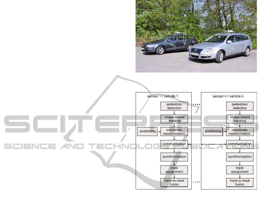
The system setup consists of two test vehicles
equipped with LANCOM
R
wireless access points,
cameras, inertial sensors, GPS, and a regular PC (Fig.
1). The monochrome camera is mounted at the po-
sition of the rear-view mirror and is connected to the
PC. The vehicle bus enables the access to inertial sen-
sors and GPS. The GPS is used to generate times-
tamps for the data that is subject to transmission. The
GPS unit (AsteRxi system) delivers a position accu-
racy of a around 2cm and a heading accuracy of 1
◦
.
The position information is obtained relative to one
Figure 1: Test vehicles.
Figure 2: System overview: Pedestrian detection and fu-
sion.
vehicle that is defined to be the dedicated master. Fi-
nally, the LANCOM
R
unit is responsible for the data
transmission.
Fig. 2 illustrates the system that is used for multi-
camera pedestrian detection and fusion. Firstly, the
image is scanned via an AdaBoost detection algo-
rithm. The pedestrian detection is based on the system
presented in (Nunn et al., 2009). The detection results
are then tracked using a Kalman filter that is work-
ing in image coordinates. The tracked detections are
then transformed to appropriate coordinates that can
be used for the fusion. These transformed detections,
including their uncertainties, are then transmitted to
the other vehicle as well as the vehicle position. The
data is then synchronized using the GPS timestamps
and passed to the track-assignment module. Corre-
sponding tracks are finally fused by means of Track-
To-Track fusion algorithms.
VISAPP 2011 - International Conference on Computer Vision Theory and Applications
308
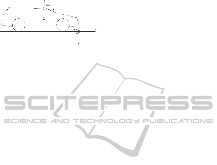
Figure 3: Definition of the VCOS and the CCOS.
3 COORDINATE
TRANSFORMATIONS
The overall task of the coordinate transformation is to
transform the detection results to a coordinate frame
that can be used by both vehicles. Here it is focused
on the positioning of the vehicles with the fixed map,
since this map, including pedestrian ground truth data,
is used for the evaluation in section 5. In general four
coordinate systems are used:
1. Image Coordinate System (ICOS) r = (x, y, 1)
T
,
2. Camera Coordinate System (CCOS)
r
C
= (x
C
, y
C
, z
C
, 1)
T
,
3. Vehicle Coordinate System (VCOS)
r
V
= (x
V
, y
V
, z
V
, 1)
T
,
4. World Coordinate System (WCOS)
r
W
= (x
W
, y
W
, z
W
, 1)
T
.
The position vectors are notated in homogeneous co-
ordinates.
The definition of the VCOS and the CCOS is
shown in Fig. 3. The transformation from the VCOS
to CCOS can be expressed by the 4 × 4 external cali-
bration matrix K
e
, which encodes the position of the
camera T and the camera rotation R
K
e
= VRT.
The matrix V simply swaps the coordinates according
to Fig. 3.
The transformation from CCOS to the ICOS is im-
plemented with a pinhole camera model (Hartley and
Zisserman, 2003). Thus, the effective focal length f
x
in x- and f
y
in y-direction are needed and the position
of the principal point p = (c
x
, c
y
). The mapping is
described by a 3 × 4 internal calibration matrix
K
i
=
f
x
0 c
x
0
0 f
y
c
y
0
0 0 1 0
.
The combination of the internal and external cal-
ibration matrices enables the transformation from the
VCOS to the ICOS by
sr = K
i
K
e
r
V
. (1)
For the WCOS that is uses in conjunction with the
map, it is assumed that the map (WCOS) and the ve-
hicle (VCOS) are located on the same plane. There-
fore a point r
W
= (x
W
, y
W
, 0, 1) can be mapped to
r
V
= (x
V
, y
V
, 0, 1) by
sr
V
= RTr
W
,
where T encodes the position of the vehicle in the
WCOS and R describes the vehicle orientation.
3.1 Mapping Pedestrian Detections to
the Vehicle Coordinate System
Equation 1 can be used to create the inverse function
for mapping image to vehicle coordinates. The prob-
lem is that the depth information is lost and some as-
sumptions have to be made. Firstly, it can be assumed
that the detected objects are located at the same plane
as the vehicle z
W
= 0 (flat ground plane assumption
(Ponsa et al., 2005)). This assumption holds for stan-
dard scenarios like highways and cross-ways. The
problem is that pitching of the vehicle, due to uneven
road, causes significant errors in the far distance. An-
other approach is to assume a standard object width
in vehicle or world coordinates (Ponsa and Lopez,
2007). This approach can handle the pitching effects
very well, but has a constant offset related to the stan-
dard width assumption. The mapping of a single im-
age point r with the two methods is denoted by
r
V
= f
1
(r, Φ),
r
V
= f
2
(r, w, w
V
),
where Φ is the pitch angle and w is the object width in
image coordinates and w
V
is the fixed width assump-
tion in vehicle coordinates. It is obvious that the first
approach is very accurate in the near distance and the
second approach is more accurate in the far distance.
Thus, a combination of both approaches is used to cal-
culate the pedestrian positions in the VCOS.
The tracked pedestrian detections are described by
their image positions r = (x, y, 1) and the width w of
the bounding box. In addition, the tracker delivers the
uncertainties of the position and the width by means
of a covariance matrix C. Furthermore a fixed vari-
ance of the pitch angle Φ is assumed.
Using the detection result and the information
about the uncertainties, the detections are then treated
as two 3-D normal distributions N (µ
1
, C
1
) and
N (µ
2
, C
2
), where µ
1
= (x, y, Φ) describes the object
position and the pitch angle and µ
2
= (x, y, w) de-
scribes the object position and the object width. C
1
and C
2
are the according covariance matrices.
MULTI-CAMERA PEDESTRIAN DETECTION BY MEANS OF TRACK-TO-TRACK FUSION AND CAR2CAR
COMMUNICATION
309

Since f
1
(r, Φ) and f
2
(r, w, w
V
) are non-linear, it
is proposed to use the scaled unscented transforma-
tion (SUT) (Merwe and Wan, 2003) to map the dis-
tribution from image to vehicle coordinates. For ap-
plying the SUT a set of deterministic sigma points
is chosen and these points are then propagated us-
ing the non-linear function. The sigma points x
i
and
the weight values w
m
i
and w
c
i
are chosen according to
(Merwe and Wan, 2003)
x
0
= µ
x
i
= µ +
p
(L + λ)C
i
; for i = 1,.., L
x
i
= µ −
p
(L + λ)C
i−L
; for i = L + 1, .., 2L
w
m
i
=
λ
L + λ
; for i = 0
w
c
i
=
λ
L + λ
+
1 − α
2
+ β
; for i = 0
w
c
i
= w
m
i
=
1
2(L + λ)
; for i > 0,
where L is the dimension (here L = 3) and λ =
α
2
(L + κ) −L is a scaling parameter. Moreover α de-
fines the spread of the sigma points (1e − 2 ≤ α ≤ 1).
κ is another scaling parameter that is usually set to
0 or L − 3. Finally, β can be used to incorporate
knowledge of the distribution (β = 2 for Gaussian
distribution).
p
(L + λ)C
i
is the i-th column of the
matrix square root of the covariance.
After the determination of the sigma points, they
are propagated using the non-linear functions f
1
and
f
2
y
i
= f (x
i
).
The weight values and the sigma point can now be
used to recover the statistics of the distribution after
the non-linear transformation by means of
˜µ =
2L
∑
i=0
w
m
i
y
i
˜
C =
2L
∑
i=0
w
c
i
(y
i
− ˜µ) (y
i
− ˜µ)
T
.
For both functions f
1
and f
2
an estimate of the posi-
tion in the VCOS is obtained. Since it is known, that
the first one is better in the near distance d and the
latter is superior in the far distance, this information
is taken into account by using a weighting function.
The weighting function involves a scaled sigmoid
function and is 0 for d ≤ d
min
and 1 for d ≥ d
max
. For
distance values d
min
< d < d
max
the sigmoid function
is used and scaled to values between 0 and 1. After
the weight value for each estimate is determined, the
covariance intersection equations (section 4) are used
to determine the final result. Instead of optimizing
ω = arg min[det(C)], the described weight value is
used. The approach can be summarized by
1. Describe the detections by two 3D vectors µ
1
=
(x, y, Φ), µ
2
= (x, y, w) and two 3 × 3 covariance
matrices C
1
and C
2
.
2. Calculate scaled sigma points for both distribu-
tions.
3. Propagate sigma points using f
1
and f
2
.
4. Recover statistics ˜µ
1
, ˜µ
2
,
˜
C
1
, and
˜
C
2
.
5. Determine weight value ω, based on the distance
of both estimates using the weighting function.
6. Fuse the results using covariance intersection with
fixed weight value ω.
4 FUSION OF PEDESTRIAN
DETECTIONS
Each vehicle sends the tracked detection results to the
other vehicle and receives the tracked detection re-
sults of the opponent. The detections are described
by their position and their uncertainties in the WCOS.
The state estimates of each track are denoted by µ
1
and µ
2
, whereas the fused state is µ. The accord-
ing covariance matrices are denoted by C
1
, C
2
, and
C. The fusion is subdivided into two components,
namely the track assignment and the Track-To-Track
fusion.
4.1 Track-to-Track Fusion Algorithms
Once the track assignment is completed, the tracks are
subject to fusion. As aforementioned the choice of
the fusion method depends on the data at hand and to
what extent the data or sensors are correlated. There-
fore, three well known methods are analyzed. A com-
parison of fusion methods on simulated data is given
in (Matzka and Altendorfer, 2008), a survey is given
in (Smith and Singh, 2006) and a general treatment
on data fusion can be found in (Bar-Shalom and Blair,
2000).
The first method for fusion is based on the Kalman
equations and is presented in (Smith and Cheeseman,
1986). In this work a different notation is used, that
is described in (Bar-Shalom and Blair, 2000), but that
result is equivalent to (Smith and Cheeseman, 1986).
For the evaluation this method it is denoted by Co-
variance Fusion (CF) for uncorrelated data, which
VISAPP 2011 - International Conference on Computer Vision Theory and Applications
310
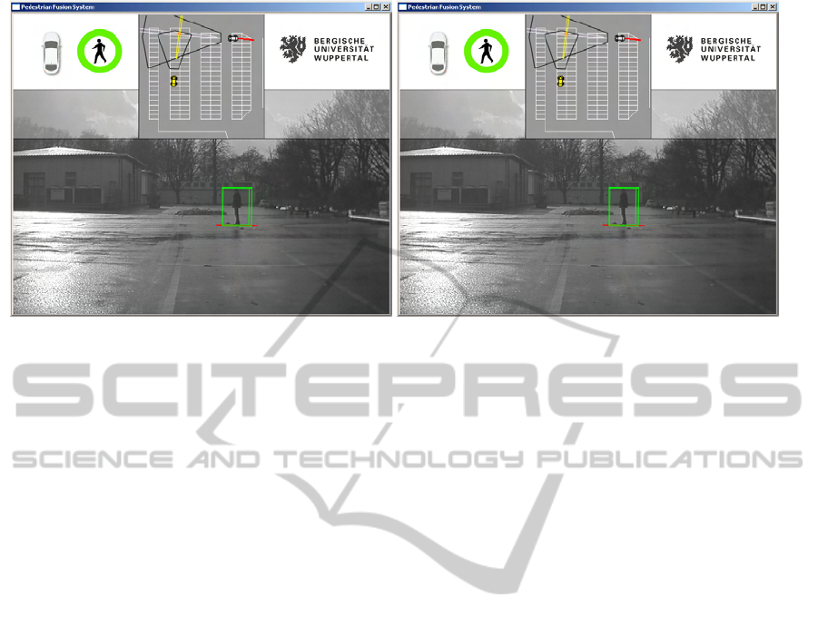
(a) View from vehicle 1. (b) View from vehicle 2.
Figure 4: Results of pedestrian detection fusion from two vehicles. Fig. 4(a) and 4(b) are recorded at the same timestamp.
The ego vehicle is gray and the remote vehicle is yellow. The trajectory of the vehicles is denoted by red dots.
can be defined by the following equations
C = C
1
(C
1
+ C
2
)
−1
C
2
µ = C
2
(C
1
+ C
2
)
−1
µ
1
+ C
1
(C
1
+ C
2
)
−1
µ
2
.
The second method is the Covariance Intersection
(CI) (Matzka and Altendorfer, 2008). This method is
known to work well in situations where signals are
correlated, but the correlation is unknown. The CI
can be implemented using
C
−1
= ωC
−1
1
+ (1 − ω)C
−1
2
µ = C
ωC
−1
1
µ
1
+ (1 − ω)C
−1
2
µ
2
ω = argmin[det(C)].
ω defines the influence of each estimate and is deter-
mined by an optimization procedure that minimizes
e.g. det(C). Consistent estimates are guaranteed for
ω ∈ [0, 1].
The third method is named Covariance Union
(CU) (Matzka and Altendorfer, 2008) and is defined
by
˜
C
1
= C
1
+ (µ − µ
1
)(µ − µ
1
)
T
˜
C
2
= C
2
+ (µ − µ
2
)(µ − µ
2
)
T
C = max
˜
C
1
,
˜
C
2
µ = argmin[det(C)].
Just like for CI, an optimization procedure has to be
applied for CU to determine µ. The advantage of the
CU is that this method is able to resolve statistically
inconsistent states. This problem is faced by deter-
mining a new state estimate that can exceed the co-
variance indicated by at least one track (Matzka and
Altendorfer, 2008).
5 EVALUATION
The evaluation of the three fusion methods is per-
formed on real data (see Fig. 4). The positioning of
the vehicles is performed by means of image registra-
tion in conjunction with an environment map. This
map is used to determine the starting position and ori-
entation of the vehicles. The vehicle movement is
then calculated using the IMU and the motion model
presented in (Meuter et al., 2008).This setup is used
for evaluation since it is easy to generate ground truth
data by using the map. The inaccuracies due to the
movement of the vehicle are negligible compared to
the errors induced by the object distance calculation
from a single camera.
The system is tested on various video-sequences
and different scenarios. The used scenarios are based
on typical cross-way situations. In the first scenario
both vehicles are approaching the object with an angle
difference of 90
◦
and in the second scenario the vehi-
cles are placed at an angle difference of 180
◦
. The
distance of the vehicles to the objects at the starting
position goes up to around 50m.
To demonstrate the advantage of the fusion, firstly
the detection results of the individual vehicles are
evaluated. The results of the RMSE are shown in Ta-
ble 1. As expected the lateral position of the objects
can be measured precisely, whereas the depth infor-
mation is inaccurate.
The results in Table 2 reveal that the fusion dra-
matically improves the overall precision. Whatever
fusion method is used, the RMSE of d
w
(distance
of ground truth object and prediction) gets improved.
For the first scenario the CI performs best and for the
MULTI-CAMERA PEDESTRIAN DETECTION BY MEANS OF TRACK-TO-TRACK FUSION AND CAR2CAR
COMMUNICATION
311
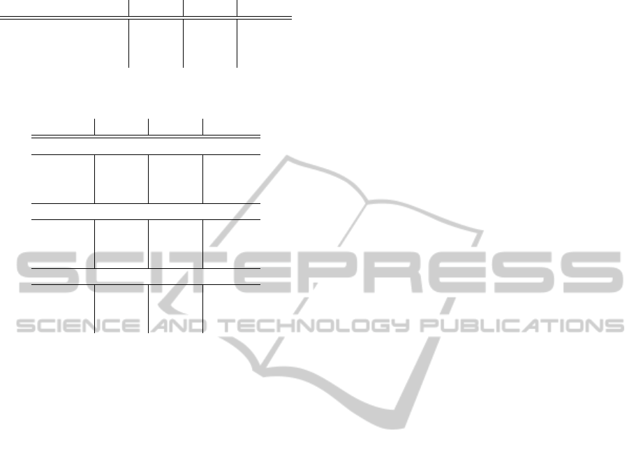
Table 1: RMSE: single vehicles.
scenario x
w
[m] y
w
[m] d
w
[m]
scenario 1 0.68 4.18 4.28
scenario 2 3.72 0.98 4.05
overall performance 1.89 2.90 4.19
Table 2: RMSE: fusion of two vehicles.
Method x
w
[m] y
w
[m] d
w
[m]
scenario 1
CF 0.35 0.55 0.69
CI 0.35 0.55 0.69
CU 2.87 2.67 3.94
scenario 2
CF 0.15 1.00 1.01
CI 0.14 1.07 1.08
CU 0.15 3.72 3.73
overall performance on both scenarios
CF 0.25 0.78 0.85
CI 0.24 0.81 0.89
CU 1.51 3.19 3.83
second scenario the CF outperforms the other algo-
rithms. In contrast to the results presented in (Matzka
and Altendorfer, 2008) the CU has the worst perfor-
mance in all scenarios. Based on these results it is
proposed to use the CF as a general fusion method,
since the algorithm delivers precise results in all sce-
narios. One could imagine a combination of CF and
CI to get the best results in all situations. It is not sur-
prising that the CF and CI deliver similar good results
as long as the position vectors r
w
of the detections are
relatively accurate. For each vehicle the lateral po-
sitions of the detections are very accurate. Thus one
could get a fused result of two cameras by calculating
the intersection of the two rays on which the detec-
tions are located. This is similar to stereo vision. The
fused position vector of CF and CI is close to the re-
sult that would be obtained by this ray intersection.
The main difference of CI and CU is determined by
the fused covariance.
This leads to the scenario where CU could out-
perform CF and CI. Inconsistent states are obtained if
lateral position errors occur due to erroneous data of
the detection algorithm or an erroneous vehicle po-
sition. These states can then be handled by a CU
algorithm. It would make sense to include an algo-
rithm that can detect where inconsistent states occur
and then change the fusion algorithm to CU.
ACKNOWLEDGEMENTS
The developed system is part of the Active Safety Car
project which is co-funded by the European Union
and the federal state NRW.
REFERENCES
Bar-Shalom, Y. and Blair, W. D. (2000). Multitarget-
Multisensor Tracking: Applications and Advances.
Artech House Inc, Norwood, USA.
Hartley, R. and Zisserman, A. (2003). Multi View Geometry
in Computer Vision (2nd Edition). Cambridge Univer-
sity Press, Cambridge, United Kingdom.
Kaempchen, N. (2007). Feature-level fusion of laser scan-
ner and video data for advanced driver assistance sys-
tems. Technical report, Fakultaet fuer Ingenieurwis-
senschaften und Informatik, Universitaet Ulm.
Matzka, S. and Altendorfer, R. (2008). A comparison of
track-to-track fusion algorithms for automotive sensor
fusion. In Proc. of International Conference on Mul-
tisensor and Integration for Intelligent Systems , 2008
IEEE, pages 189–194.
Merwe, R. V. D. and Wan, E. (2003). Sigma-point kalman
filters for probabilistic inference in dynamic state-
space models. In In Proceedings of the Workshop on
Advances in Machine Learning.
Meuter, M., Iurgel, U., Park, S.-B., and Kummert, A.
(2008). The unscented kalman filter for pedestrian
tracking from a moving host. In Proc. of Intelligent
Vehicles Symposium, 2008 IEEE, pages 37–42.
Nunn, C., Kummert, A., Muller, D., Meuter, M., and
Muller-Schneiders, S. (2009). An improved adaboost
learning scheme using lda features for object recogni-
tion. In Proc. of Intelligent Transportation Systems,
2009. ITSC ’09. 12th International IEEE Conference
on, pages 1–6.
Ponsa, D. and Lopez, A. (2007). Vehicle trajectory es-
timation based on monocular vision. In Marti, J.,
Benedi, J., Mendonca, A., and Serrat, J., editors, Pat-
tern Recognition and Image Analysis, volume 4477 of
Lecture Notes in Computer Science, pages 587–594.
Springer Berlin / Heidelberg.
Ponsa, D., Lopez, A., Lumbreras, F., Serrat, J., and Graf,
T. (2005). 3d vehicle sensor based on monocular vi-
sion. In Proceedings of the 8th International IEEE
Conference on Intelligent Transportation Systems, Vi-
enna, Austria.
Smith, D. and Singh, S. (2006). Approaches to multisen-
sor data fusion in target tracking: A survey. Knowl-
edge and Data Engineering, IEEE Transactions on,
18(12):1696 –1710.
Smith, R. C. and Cheeseman, P. (1986). On the representa-
tion and estimation of spatial uncertainly. Int. J. Rob.
Res., 5(4):56–68.
VISAPP 2011 - International Conference on Computer Vision Theory and Applications
312
