
A NEW TERRAIN DATA COMPRESSION SCHEME FOR
INTERACTIVE TERRAIN VISUALIZATION SYSTEMS
Ricardo Olanda, Mariano Pérez and Juan Manuel Orduña
Departamento de Informática, University of Valencia, Valencia, Spain
Keywords: Virtual reality, Terrain data compression, Interactive terrain visualization, JPEG2000.
Abstract: Over the last years, there has been a great development on real time terrain visualization applications using
remote databases. One of the main problems that these applications must face is the storage and
transmission of terrain data. Despite the considerable bandwidth increase of internet connection during last
years, the large amount of data to be transmitted can easily saturate these connections. On other hand, since
data must be stored in the client side, clients need a considerable storage space. In this context, we propose a
new compression scheme that solves or minimizes these problems. It is based on JPEG2000 standard;
however, the wavelet analysis and synthesis algorithms are modified to allow efficient transmission and
reconstruction of terrain data by using tiled pyramids multiresolution techniques. A comparative study
including current techniques shows that the proposed scheme obtains a better compression ratio of the
terrain data, reducing the storage space and transmission bandwidth needed, achieving a better visual quality
of terrain data reconstructed after data decompression.
1 INTRODUCTION
Real-time terrain visualization is a very active
research field in the area of computer graphics.
Some applications examples in this area are driving
or flight simulator, cartography applications or
virtual worlds visualization.
These applications usually use a client-server
architecture to transmit terrain data over the Internet.
In this architecture, the terrain visualization
component runs on the local host (client) and the
terrain database component runs on a remote server.
In order to visualize the terrain data, the most
commonly used strategy is to define a
multiresolution hierarchy for a data set, splitting
each level of resolution of the terrain data into a set
of fixed-size regular tiles (rectangular non-
overlapping blocks). This process is known as tiling.
All the tiles form a tiled pyramid as shown in
Figure 1 - a. This figure shows four resolution levels
of a terrain dataset. Each resolution level is split into
tiles of the same size, so the number of tiles
decreases with the resolution level.
In order to visualize the terrain data, initially a
lower resolution tile is transmitted. If more
resolution is needed, this tile is replaced with the
next level of resolution tiles. This process is repeated
until required visual quality of the terrain is reached.
This structure was initially used by Goss and
(Yuasa, 1998) and (Cline and Egbert, 1998). This,
and similar structures (Okamoto, de Mello and
Esperança, 2008) have been used later in multiple
works because allow a progressive and independent
transmission of the different terrain regions.
The data structures commonly used in these
applications are heightmaps, that describe the terrain
surface, and texture images that provide a more
realistic appearance of the terrain. Both of them can
be encoded as an image. Therefore, techniques used
for texture compression can also be applied to
compress the heightmap data.
JPEG2000 image compression standard (JPEG
Committee, 2004) has been proved to be one of the
best image compression algorithms available for the
moment. However, in order to use this standard in a
terrain visualization application, several problems
must be solved. One of these problems is due to the
fact that the original JPEG2000 standard does not
properly suit the tiled pyramid scheme used to
organize data in terrain visualization applications.
In this paper, we propose a new data
compression scheme for remote terrain visualization
systems. We have performed a comparative studio
280
Olanda R., Pérez M. and Orduña J..
A NEW TERRAIN DATA COMPRESSION SCHEME FOR INTERACTIVE TERRAIN VISUALIZATION SYSTEMS.
DOI: 10.5220/0003324402800285
In Proceedings of the International Conference on Computer Graphics Theory and Applications (GRAPP-2011), pages 280-285
ISBN: 978-989-8425-45-4
Copyright
c
2011 SCITEPRESS (Science and Technology Publications, Lda.)

including current techniques. The results show that
the proposed compression scheme obtains a better
compression ratio of the terrain data, reducing the
storage space and the required transmission
bandwidth and providing a better visual quality of
terrain data in real time visualization. Moreover, this
new scheme fits the tiled pyramid that terrain
visualization applications usually use to manage
large terrain databases.
2 RELATED WORK
Nowadays, compression schemes based on discrete
wavelet transform (DWT) have been proved to be
the most efficient way to compress images. Some of
these schemes can be found in the survey done by
Sudhakar, Karthiga and Jayaraman (2005).
Several authors have combined data compression
methods with multiresolution schemes to reduce the
bandwidth and memory requirements for terrain
visualization applications. For example, Gioia,
Aubault and Bouville (2004) and Kim and Ra (2004)
use wavelet transform for geometry reconstruction
of the terrain over the network, and Royan, Gioia,
Cavagna and Bouville (2007) use wavelet transform
for coding and transmitting the terrain geometry.
These works use different techniques that are
able to provide high rates of compression,
progressive transmission and random spatial access.
Among them, the JPEG2000 standard compression
scheme can be emphasized. One example of its use
is the work of Lin, Huang and Chen (2007), that
uses JPEG2000 standard for 3D geometric objects
compression and transmission.
Many other authors have developed compressed
geometry representations, but in most cases they are
oriented to achieve high compression rates instead of
focusing on fast algorithms, more suitable for real
time visualization (Alliez and Gostman, 2005).
3 DATA COMPRESSION
As it was discussed in the previous section,
JPEG2000 standard is one of the best image
compression schemes. The purpose of our work is
the adaptation of JPEG2000 standard for its use in
terrain visualization applications, and the evaluation
of its performance with respect to current
techniques. For comparison purposes, we have
implemented four possible strategies.
3.1 Strategy 1: No Information Reused
This strategy consists in generating a different image
for each level of resolution of the tiled pyramid
(Figure 1 - a). Each one of these images are split in
tiles, which are transmitted and decompressed in an
independent way, as isolated images, without using
information of tiles belonging to lower levels of
resolution, which were previously transmitted.
The total amount of data for the whole tiled
pyramid represents an overhead of 33 % with
respect to the image with the higher resolution level
of the tiled pyramid (Goss and Yuasa, 1998).
This strategy is usually used for terrain
visualization in applications like Google Earth
(Google, 2010).
3.2 Strategy 2: JPEG2000 with Tiling
JPEG2000 standard allows splitting an original
image into a group of smaller regular images that are
then compressed and transmitted in an independent
way. The compression/decompression scheme of
JPEG2000 tiling is shown in Figure 2. In this
compression scheme, the image is split into tiles and
the wavelet transform is applied to each tile in an
independent way (JPEG Committee, 2004).
a b
Figure 1: a) Tiled pyramid with 4 different resolution
levels. b) JTiles in Tiled Pyramid.
We will denote the tiles generated by the
JPEG2000 compression scheme as JPEG2000 tiles
(JTiles), in order to avoid confusion with the tiles
used in a tiled pyramid.
The main problem of this scheme is that the
number of JTiles generated at every resolution level
is always the same, and its size is decreased (Figure
1 - b), so this scheme do not match with the tiles
used in a tiled pyramid (where the number of tiles
decrease and its size remains constant) and it will be
necessary to transmit and combine several of these
JTiles to obtain an equivalent tile of the tiled
A NEW TERRAIN DATA COMPRESSION SCHEME FOR INTERACTIVE TERRAIN VISUALIZATION SYSTEMS
281
pyramid. These differences can be observed
comparing Figure 1 - a and Figure 1 - b.
Figure 2: JPEG2000 standard with tiling scheme, a)
Compression, b) Reconstruction.
This strategy is used by Hayat et al. (2010) to do
online 3D terrain visualization.
3.3 Strategy 3: JPEG2000 without
Tiling
If the tiling process is not used, then JPEG2000
generates only one JTile for each resolution level of
the tiled pyramid. If a region of this JTile is
reconstructed in an independent way, visual artifacts
appear at the borders of these regions, as we will
show in section 4.1.
This is due to the fact that in the analysis process
JPEG2000 uses information different from the used
in the analysis process and in the synthesis process.
In the analysis process, all the image data are used to
generate all the wavelet coefficients, but in the
synthesis process (in order to reconstruct a tile of the
tiled pyramid in an independent way) only the
coefficients placed inside the region matching the
tile are used to reconstruct this terrain region,
without using neighboring coefficients that were
used in the analysis process.
The compression/decompression scheme is the
same shown in Figure 2, but now without using the
tiling process.
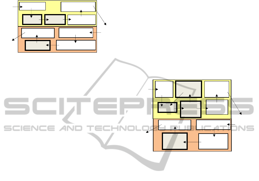
3.4 Strategy 4: New Scheme
In order to solve the problems of the previous
strategies, we have modified the compression
scheme as is shown in Figure 3 - a. This scheme is
similar to the one used by JPEG2000 standard; the
main differences are the image tiling process and the
wavelet transform application.
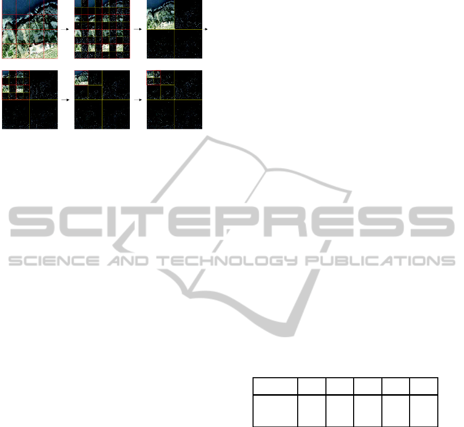
A wavelet analysis example following this
scheme is shown in Figure 4. Before each wavelet
transform step is applied, the image is split into
several tiles of fixed size (Figure 4-a). (JPEG2000
standard initially splits the image into JTiles only
once). Then, a 2D analysis filter is applied to each
tile, generating four coefficients sub-bands: a low-
pass sub-band (LL) and three high-pass sub-bands
(HL, LH and HH) (Figure 4-b). The coefficients of
the high-pass sub-bands are grouped into code-
blocks, quantized and entropy encoded in an
independent way, similarly to the way JPEG2000
standard does. Before a new wavelet transform step
takes place, all low-pass sub-bands (LL) are grouped
into a lower resolution version of the image (Figure
4-c). This process is repeated until this lower
resolution version size is smaller than the tile size
(Figure 4-d, 4-e, 4-f).
Figure 3: New scheme a) Compression, b) Reconstruction.
In order to reconstruct these tiles, the inverse
process takes place in a progressive way ( Figure 3 –
b), but using the inverse DWT module properly
modified to apply only one step. Once a tile has been
reconstructed, any children tile can be reconstructed
by decompressing and applying one wavelet
transform step, joining the coefficients of the
children tiles sub-bands HL, LH and HH with data
of the father tile sub-band LL.
This tile reconstruction is perfect, without visual
artifacts in the region frontiers, because the same
coefficients are used for the synthesis and the
analysis process of the wavelet transform, avoiding
the use of coefficients that belong to neighboring
tiles in both processes, unlike the JPEG2000
standard scheme used in strategy 3. Additionally,
these modifications allow the number of generated
tiles to fit in the tiled pyramid.
These modifications slightly increases the time
required to compress the data with respect to the
original compression scheme, due to the process to
recombine the LL sub-bands. Nevertheless, the
compression of the data is done off-line, and
therefore it does not affect to the performance of the
terrain visualization application.
Compressed
Image Data
Reconstructed
Image / Tile
Tiling
Color
Transf.
DWT
(1 step)
Quant
i
-
zation
Entropy
Encoding
Source
Image
Inverse Color Tr.
Inverse
Quantization
Entropy Decoding
Inv. DWT
(1 step)
Recombine
LL
a)
Compressed
Image Data
Recons-
tructed
Image / Tile
Tiling
Color Transf.
DWT
Quantization
Entropy Encoding
Source
Image
Inverse Color Tr.
Inverse Quantization
Entropy Decoding
b)
Inv. DWT
a)
GRAPP 2011 - International Conference on Computer Graphics Theory and Applications
282
d e f
Figure 4: Decomposition process over an image.
The time requiring for decompress the data is
similar to the original compression scheme, the
difference is that in the original scheme all the steps
of the inverse DWT were applied consecutively and
now they are applied in an independent way.
4 EVALUATION AND TESTING
A generic application of terrain visualization has
been used to compare the different compression
scheme strategies. This application consists of
performing a real time fly over different terrain
databases using different visual quality parameters.
This application allows taking top view photos and
user point of view photos of the terrain surface and
storing them for analysis.
The terrain database used for this application is
formed by a set of terrain textures and heightmaps
that have been compressed using the different
compression scheme strategies described in the
previous section.
Different tests have been performed on these
databases: visual artifacts, lossless compression ratio
and lossy compression root mean square error.
4.1 Visual Artifacts
Terrain visualization systems with remote databases
need to reconstruct every tile of the tiled pyramid in
an independent way. When strategy 3 is used
(JPEG2000 without tiling scheme) to reconstruct a
terrain region in an independent way, visual artifacts
will appear in the frontiers of these regions. These
artifacts do not appear in the other considered
strategies.
This test checks visual artifact impact for the
different strategies. In order to achieve this goal, our
terrain visualization application has taken top view
photos of the terrain database that have been lossless
compressed using the different compression
strategies. The terrain images have been
reconstructed by regions in an independent way.
Figure 5 shows a representative example of the
visual artifacts obtained when using strategy 3.
Figure 5-a shows an example of user point of view
inside terrain visualization application. Figure 5-b
shows the terrain dataset (at high resolution)
corresponding to the terrain region viewed by the
user at that moment. Figure 5-c and 5-d show the
tiles used from the tiled pyramid at that user point of
view by strategy 3 and 4 respectively. Figure 5-c
shows visual artifacts in the frontiers between terrain
regions of the same level of resolution. These visual
artifacts do not appear in Figure 5-d. These
differences have been emphasized by red ellipses.
In order to evaluate the visual quality in a
quantitative way, five resolution levels of the terrain
surface (Figure 5) have been reconstructed by tiles
of the same resolution in an independent way, and
theirs root mean square error (RMSE) have been
measured in relation to the high resolution terrain
surface.
Table 1 shows the results for the strategy 3 and
4. Strategy 1 and 2 results are similar to the strategy
4 ones, because in these strategies do not appear
visual artifacts.
Version 0 corresponds to the lowest level of
resolution, and version 4 corresponds with the
highest resolution reconstruction.
Table 1: Image Figure 5 RMSE.
Version 0 1 2 3 4
Strategy 3 83,10 71,76 58,17 38,03 13,84
Strategy 4 82,51 70,61 55,29 34,14 0,00
The error using the strategy 3 is greater than the
error obtained when others strategies are used.
Moreover, strategy 3 does not achieve a perfect
reconstruction of the image at high resolution, unlike
the rest of strategies.
This behavior is due to the fact that strategy 3
has used all image data in the analysis process, but
only the transmitted tile coefficients have been used
in the synthesis process, when also the neighbor data
would be needed. These visual artifacts are extended
in each synthesis process of the wavelet transform,
causing an imperfect reconstruction of the complete
image.
As a result, we can conclude that strategy 3 is not
valid to be used for a terrain visualization
application, due to the fact that visual artifacts will
appear, resulting in a low quality terrain
visualization.
a b c
A NEW TERRAIN DATA COMPRESSION SCHEME FOR INTERACTIVE TERRAIN VISUALIZATION SYSTEMS
283
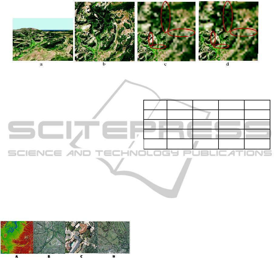
Figure 5: Visual artifacts image examples.
4.2 Lossless Compression Ratio
Terrain data size is an important factor, since it
affects the amount of storage required, the
bandwidth and the time required to transmit the data.
In order to analyze the compression rate that
each compression scheme can reach, a set of
different terrain images have been compressed using
different tile sizes. Some examples of these images
are shown in Figure 6.
In order to measure the compression rate, we
divide the size of the uncompressed image at full
resolution by the size of the compressed image ready
to generate the tiled pyramid.
Table 2 shows a representative example of the
compression ratio achieved for the different
strategies when applied to the Figure 6 images using
a tile size of 128 pixels. The size of these images
goes from 2048x2048 till 16384x16384 pixels.
Figure 6: Four images used for compression test.
Table 2 shows that compression ratios provided
by strategies 3 and 4 are equal, and better than those
achieved by strategies 1 and 2. This is due to the fact
that strategy 1 has to transmit different images for
each level of resolution of the tiled pyramid, and the
compressed image size will be not only the high
level resolution image compressed size, but the
addition of the size of each different resolution
image. On other hand, strategy 2 treats each tile like
an isolated image, thus limiting the amount of data
available for the compression algorithm.
As a result, we can conclude that strategy 4
scheme provide the best compression ratio without
producing visual artifact.
Table 2: Compression ratio for Figure 6 images using the
four strategies.
Image A Image B Image C Image D
Strat. 1
1,67 1,78 1,68 2,36
Strat. 2 2,37 2,52 2,34 3,45
Strat. 3 2,41 2,56 2,37 3,55
Strat. 4 2,41 2,56 2,37 3,55
4.3 Lossy Compression Root Mean
Square Error (RMSE)
Lossy compression introduces errors in each
analysis step of the wavelet transform, degrading the
reconstructed image at each reconstruction step.
Nevertheless, this type of compression can be useful
to reduce both the data size and the transmission
time.
In order to study which compression scheme
provides higher visual quality when using lossy
compression, a set of images have been compressed
using different bit rates. These images have been
decompressed using all the information of each level
of the tiled pyramid. The RMSE with respect to the
original image has been measured.
Table 3 shows the lossy compression results in a
quantitatively way. It shows the RMSE value
obtained for the different strategies using different
compression ratios for the image Figure 6-C. The
image size is 2048x2048 pixels, using a tile size of
128x128 pixels (except for strategy 3, where the
tiling process was not applied).
Table 3 shows that strategies 3 and 4 obtain
image reconstructions of similar quality (and better
than the strategies 1 and 2), although strategy 4
applies a tiling process and no tiles have been used
for strategy 3.
The reason for this behavior is that strategy 1
repeats the information that has to transmit (the bit
rate is measured taking into account all the different
resolution images inside de tiling pyramid), so the
GRAPP 2011 - International Conference on Computer Graphics Theory and Applications
284

data size is higher than the other strategies.
Table 3: RMSE – Lossy compression.
Strat. 1 Strat. 2 Strat.3 Strat. 4
bpp RMSE RMSE RMSE RMSE
0,05 30,28 35,80 27,99 28,22
0,10 25,33 27,52 22,83 23,03
0,15 21,89 22,82 19,73 19,95
0,25 17,67 17,47 15,05 15,26
1,00 7,54 6,72 5,98 6,03
2,00 4,04 3,39 3,02 3,07
3,00 2,58 2,09 1,88 1,91
4,00 1,88 1,49 1,38 1,40
Regarding the strategy 2, each tile is treated like
an isolated image, causing a lower image quality and
block effect. This block effect appears when a low
compression ratio is used (for example 0.05 bpp).
Table 3 also shows that strategy 1 is better than
strategy 2 for lower values of bpp, but it is worst for
higher values of bpp. This is due to the fact that
strategy 2 suffers from a smaller block effect as bpp
is increased.
As a result, we can conclude that the proposed
scheme results in the best performance providing
similar lossy compression rates than strategy 3,
although it does not provide visual artifacts.
5 CONCLUSIONS
In this paper, we have proposed a new compression
scheme for terrain data to be used in remote terrain
visualization systems, performing a comparative
study with other three different strategies that can be
used in terrain visualization applications.
The performance evaluation results show that the
proposed scheme:
Reuses previous information transmitted,
reducing the data to be transmitted.
It obtains a good compress ratio and visual
quality.
It can reconstruct terrain regions in an
independent way, avoiding visual artifacts in
the borders of these regions.
It suits the tiled pyramid usually used to
organize terrain data.
Meanwhile, strategy 1 does not reuse previous
information transmitted, so it needs to transmit more
data than the other strategies. Strategy 2 obtains a
lower compress ratio and visual quality than the
other strategies, and strategy 3 produces visual
artifacts at the region borders when these regions are
reconstructed in an independent way.
These results show that the proposal scheme can
significantly improve the performance of remote
terrain visualization systems.
ACKNOWLEDGEMENTS
This work has been jointly supported by the Spanish
MICINN and the European Commission FEDER
funds under grants Consolider-Ingenio 2010
CSD2006-00046 and TIN2009-14475-C04-04.
REFERENCES
Alliez P., Gostman C., 2005. Recent advances in
compression of 3d meshes. Advances in
Multirresolution for Geometric Modelling. Springer.
Cline D., Egbert P., 1998. Interactive display of very large
textures. IEEE Visualization, 343-350.
Gioia P., Aubault O., Bouville C., 2004. Real-Time
reconstruction of wavelet-encoded meshes for view-
dependent transmission and visualization. IEEE
TCSVT, vol. 14 (7), 1009-1020.
Google, 2010. Google Earth home page. Retrieved
November 11, 2010 from http://earth.google.com.
Goss M. E., Yuasa K., 1998. Texture tile visibility
determination for dynamic texture loading.
Eurographics/Siggraph workshop on Graphics
Hardware, 55-60.
Hayat K., Puech W, Islam N., Gesquiere G., 2010.
Seamless heterogeneous 3D tessellation via DWT
domain smoothing and Mosaicking. Eurasip Journal
on Advances in Signal Processing.
JPEG Committee, 2004. JPEG2000 – ISO/IEC 15444 –
Information Technology, JPEG2000 Image Coding
System: Core Coding System.
Kim J. K., Ra J. B., 2004. A real-time terrain visualization
algorithm using wavelet based compression. The
Visual Computer, vol. 12 (2), 67-95.
Lin N. S., Huang T. H., Chen B. Y., 2007. 3D model
streaming based on JPEG2000. IEEE TCE, vol. 53 (1).
Okamoto R. M., de Mello F. L., Esperança C, 2008.
Texture management in view dependent application
for large 3d terrain visualization. Spring Simulator
conference, 641-647.
Royan J., Gioia P., Cavagna R., Bouville C., 2007.
Network-based visualization of 3d landscapes and city
models. IEEE Computer Graphics and Applications,
vol. 27 (6), 70-79.
Sudhakar R., Karthiga R., Jayaraman S., 2005. Image
compression using coding of wavelet coefficients – A
survey. GVIP journal, vol. 5 (6).
A NEW TERRAIN DATA COMPRESSION SCHEME FOR INTERACTIVE TERRAIN VISUALIZATION SYSTEMS
285
